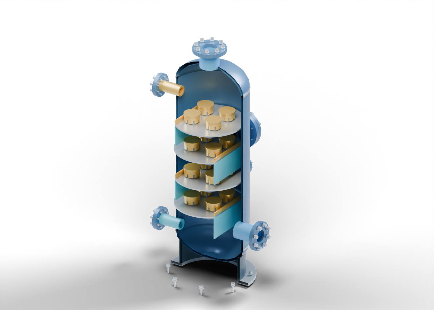
Contactor vessel wall
Hollow vertical enclosure with actual side-connection and manway openings. Invented thickness and geometry; no pressure vessel qualification.
Contactor upper head
Original hollow curved upper head with a centre outlet opening. No standard head shape, stress or pressure rating.
Contactor lower head
Hollow curved lower-head concept with an annular low-end region and separate closure marker. No drain or qualified pressure boundary.
Lower-head closure marker
Static solid low-end closure marker. No drain, nozzle attachment or rated fabrication.
Upper circumferential seam
Separate geometric seam marker. No weld preparation or examination result.
Lower circumferential seam
Separate geometric seam marker. No fabrication or rated joint.
Support skirt
Hollow support marker below the lower head. No anchorage, load or foundation design.
Skirt base ring
Annular base marker with eight actual anchor holes. No foundation or structural qualification.
Base anchors stud 1
Separate smooth stud marker in a drilled joint. No threads, bolt load or rated retention.
Base anchors washer 1
Separate annular washer marker. No load or material specification.
Base anchors nut 1
Separate bored circular nut marker. Unthreaded; no torque or qualified joint.
Base anchors stud 2
Separate smooth stud marker in a drilled joint. No threads, bolt load or rated retention.
Base anchors washer 2
Separate annular washer marker. No load or material specification.
Base anchors nut 2
Separate bored circular nut marker. Unthreaded; no torque or qualified joint.
Base anchors stud 3
Separate smooth stud marker in a drilled joint. No threads, bolt load or rated retention.
Base anchors washer 3
Separate annular washer marker. No load or material specification.
Base anchors nut 3
Separate bored circular nut marker. Unthreaded; no torque or qualified joint.
Base anchors stud 4
Separate smooth stud marker in a drilled joint. No threads, bolt load or rated retention.
Base anchors washer 4
Separate annular washer marker. No load or material specification.
Base anchors nut 4
Separate bored circular nut marker. Unthreaded; no torque or qualified joint.
Base anchors stud 5
Separate smooth stud marker in a drilled joint. No threads, bolt load or rated retention.
Base anchors washer 5
Separate annular washer marker. No load or material specification.
Base anchors nut 5
Separate bored circular nut marker. Unthreaded; no torque or qualified joint.
Base anchors stud 6
Separate smooth stud marker in a drilled joint. No threads, bolt load or rated retention.
Base anchors washer 6
Separate annular washer marker. No load or material specification.
Base anchors nut 6
Separate bored circular nut marker. Unthreaded; no torque or qualified joint.
Base anchors stud 7
Separate smooth stud marker in a drilled joint. No threads, bolt load or rated retention.
Base anchors washer 7
Separate annular washer marker. No load or material specification.
Base anchors nut 7
Separate bored circular nut marker. Unthreaded; no torque or qualified joint.
Base anchors stud 8
Separate smooth stud marker in a drilled joint. No threads, bolt load or rated retention.
Base anchors washer 8
Separate annular washer marker. No load or material specification.
Base anchors nut 8
Separate bored circular nut marker. Unthreaded; no torque or qualified joint.
Wet-gas inlet neck
Separate hollow wet-gas inlet boundary. No flow, connected piping, composition or destination qualification.
Wet-gas inlet flange
Separate bored flange with eight geometric stud holes. No pressure class, facing or mating pipe.
Wet-gas inlet joint stud 1
Separate smooth stud marker in a drilled joint. No threads, bolt load or rated retention.
Wet-gas inlet joint washer 1
Separate annular washer marker. No load or material specification.
Wet-gas inlet joint nut 1
Separate bored circular nut marker. Unthreaded; no torque or qualified joint.
Wet-gas inlet joint stud 2
Separate smooth stud marker in a drilled joint. No threads, bolt load or rated retention.
Wet-gas inlet joint washer 2
Separate annular washer marker. No load or material specification.
Wet-gas inlet joint nut 2
Separate bored circular nut marker. Unthreaded; no torque or qualified joint.
Wet-gas inlet joint stud 3
Separate smooth stud marker in a drilled joint. No threads, bolt load or rated retention.
Wet-gas inlet joint washer 3
Separate annular washer marker. No load or material specification.
Wet-gas inlet joint nut 3
Separate bored circular nut marker. Unthreaded; no torque or qualified joint.
Wet-gas inlet joint stud 4
Separate smooth stud marker in a drilled joint. No threads, bolt load or rated retention.
Wet-gas inlet joint washer 4
Separate annular washer marker. No load or material specification.
Wet-gas inlet joint nut 4
Separate bored circular nut marker. Unthreaded; no torque or qualified joint.
Wet-gas inlet joint stud 5
Separate smooth stud marker in a drilled joint. No threads, bolt load or rated retention.
Wet-gas inlet joint washer 5
Separate annular washer marker. No load or material specification.
Wet-gas inlet joint nut 5
Separate bored circular nut marker. Unthreaded; no torque or qualified joint.
Wet-gas inlet joint stud 6
Separate smooth stud marker in a drilled joint. No threads, bolt load or rated retention.
Wet-gas inlet joint washer 6
Separate annular washer marker. No load or material specification.
Wet-gas inlet joint nut 6
Separate bored circular nut marker. Unthreaded; no torque or qualified joint.
Wet-gas inlet joint stud 7
Separate smooth stud marker in a drilled joint. No threads, bolt load or rated retention.
Wet-gas inlet joint washer 7
Separate annular washer marker. No load or material specification.
Wet-gas inlet joint nut 7
Separate bored circular nut marker. Unthreaded; no torque or qualified joint.
Wet-gas inlet joint stud 8
Separate smooth stud marker in a drilled joint. No threads, bolt load or rated retention.
Wet-gas inlet joint washer 8
Separate annular washer marker. No load or material specification.
Wet-gas inlet joint nut 8
Separate bored circular nut marker. Unthreaded; no torque or qualified joint.
Lean-glycol inlet neck
Separate hollow lean-glycol inlet boundary. No flow, connected piping, composition or destination qualification.
Lean-glycol inlet flange
Separate bored flange with eight geometric stud holes. No pressure class, facing or mating pipe.
Lean-glycol inlet joint stud 1
Separate smooth stud marker in a drilled joint. No threads, bolt load or rated retention.
Lean-glycol inlet joint washer 1
Separate annular washer marker. No load or material specification.
Lean-glycol inlet joint nut 1
Separate bored circular nut marker. Unthreaded; no torque or qualified joint.
Lean-glycol inlet joint stud 2
Separate smooth stud marker in a drilled joint. No threads, bolt load or rated retention.
Lean-glycol inlet joint washer 2
Separate annular washer marker. No load or material specification.
Lean-glycol inlet joint nut 2
Separate bored circular nut marker. Unthreaded; no torque or qualified joint.
Lean-glycol inlet joint stud 3
Separate smooth stud marker in a drilled joint. No threads, bolt load or rated retention.
Lean-glycol inlet joint washer 3
Separate annular washer marker. No load or material specification.
Lean-glycol inlet joint nut 3
Separate bored circular nut marker. Unthreaded; no torque or qualified joint.
Lean-glycol inlet joint stud 4
Separate smooth stud marker in a drilled joint. No threads, bolt load or rated retention.
Lean-glycol inlet joint washer 4
Separate annular washer marker. No load or material specification.
Lean-glycol inlet joint nut 4
Separate bored circular nut marker. Unthreaded; no torque or qualified joint.
Lean-glycol inlet joint stud 5
Separate smooth stud marker in a drilled joint. No threads, bolt load or rated retention.
Lean-glycol inlet joint washer 5
Separate annular washer marker. No load or material specification.
Lean-glycol inlet joint nut 5
Separate bored circular nut marker. Unthreaded; no torque or qualified joint.
Lean-glycol inlet joint stud 6
Separate smooth stud marker in a drilled joint. No threads, bolt load or rated retention.
Lean-glycol inlet joint washer 6
Separate annular washer marker. No load or material specification.
Lean-glycol inlet joint nut 6
Separate bored circular nut marker. Unthreaded; no torque or qualified joint.
Lean-glycol inlet joint stud 7
Separate smooth stud marker in a drilled joint. No threads, bolt load or rated retention.
Lean-glycol inlet joint washer 7
Separate annular washer marker. No load or material specification.
Lean-glycol inlet joint nut 7
Separate bored circular nut marker. Unthreaded; no torque or qualified joint.
Lean-glycol inlet joint stud 8
Separate smooth stud marker in a drilled joint. No threads, bolt load or rated retention.
Lean-glycol inlet joint washer 8
Separate annular washer marker. No load or material specification.
Lean-glycol inlet joint nut 8
Separate bored circular nut marker. Unthreaded; no torque or qualified joint.
Rich-glycol outlet neck
Separate hollow rich-glycol outlet boundary. No flow, connected piping, composition or destination qualification.
Rich-glycol outlet flange
Separate bored flange with eight geometric stud holes. No pressure class, facing or mating pipe.
Rich-glycol outlet joint stud 1
Separate smooth stud marker in a drilled joint. No threads, bolt load or rated retention.
Rich-glycol outlet joint washer 1
Separate annular washer marker. No load or material specification.
Rich-glycol outlet joint nut 1
Separate bored circular nut marker. Unthreaded; no torque or qualified joint.
Rich-glycol outlet joint stud 2
Separate smooth stud marker in a drilled joint. No threads, bolt load or rated retention.
Rich-glycol outlet joint washer 2
Separate annular washer marker. No load or material specification.
Rich-glycol outlet joint nut 2
Separate bored circular nut marker. Unthreaded; no torque or qualified joint.
Rich-glycol outlet joint stud 3
Separate smooth stud marker in a drilled joint. No threads, bolt load or rated retention.
Rich-glycol outlet joint washer 3
Separate annular washer marker. No load or material specification.
Rich-glycol outlet joint nut 3
Separate bored circular nut marker. Unthreaded; no torque or qualified joint.
Rich-glycol outlet joint stud 4
Separate smooth stud marker in a drilled joint. No threads, bolt load or rated retention.
Rich-glycol outlet joint washer 4
Separate annular washer marker. No load or material specification.
Rich-glycol outlet joint nut 4
Separate bored circular nut marker. Unthreaded; no torque or qualified joint.
Rich-glycol outlet joint stud 5
Separate smooth stud marker in a drilled joint. No threads, bolt load or rated retention.
Rich-glycol outlet joint washer 5
Separate annular washer marker. No load or material specification.
Rich-glycol outlet joint nut 5
Separate bored circular nut marker. Unthreaded; no torque or qualified joint.
Rich-glycol outlet joint stud 6
Separate smooth stud marker in a drilled joint. No threads, bolt load or rated retention.
Rich-glycol outlet joint washer 6
Separate annular washer marker. No load or material specification.
Rich-glycol outlet joint nut 6
Separate bored circular nut marker. Unthreaded; no torque or qualified joint.
Rich-glycol outlet joint stud 7
Separate smooth stud marker in a drilled joint. No threads, bolt load or rated retention.
Rich-glycol outlet joint washer 7
Separate annular washer marker. No load or material specification.
Rich-glycol outlet joint nut 7
Separate bored circular nut marker. Unthreaded; no torque or qualified joint.
Rich-glycol outlet joint stud 8
Separate smooth stud marker in a drilled joint. No threads, bolt load or rated retention.
Rich-glycol outlet joint washer 8
Separate annular washer marker. No load or material specification.
Rich-glycol outlet joint nut 8
Separate bored circular nut marker. Unthreaded; no torque or qualified joint.
Instrument boundary neck
Separate hollow instrument boundary boundary. No flow, connected piping, composition or destination qualification.
Instrument boundary flange
Separate bored flange with eight geometric stud holes. No pressure class, facing or mating pipe.
Instrument boundary joint stud 1
Separate smooth stud marker in a drilled joint. No threads, bolt load or rated retention.
Instrument boundary joint washer 1
Separate annular washer marker. No load or material specification.
Instrument boundary joint nut 1
Separate bored circular nut marker. Unthreaded; no torque or qualified joint.
Instrument boundary joint stud 2
Separate smooth stud marker in a drilled joint. No threads, bolt load or rated retention.
Instrument boundary joint washer 2
Separate annular washer marker. No load or material specification.
Instrument boundary joint nut 2
Separate bored circular nut marker. Unthreaded; no torque or qualified joint.
Instrument boundary joint stud 3
Separate smooth stud marker in a drilled joint. No threads, bolt load or rated retention.
Instrument boundary joint washer 3
Separate annular washer marker. No load or material specification.
Instrument boundary joint nut 3
Separate bored circular nut marker. Unthreaded; no torque or qualified joint.
Instrument boundary joint stud 4
Separate smooth stud marker in a drilled joint. No threads, bolt load or rated retention.
Instrument boundary joint washer 4
Separate annular washer marker. No load or material specification.
Instrument boundary joint nut 4
Separate bored circular nut marker. Unthreaded; no torque or qualified joint.
Instrument boundary joint stud 5
Separate smooth stud marker in a drilled joint. No threads, bolt load or rated retention.
Instrument boundary joint washer 5
Separate annular washer marker. No load or material specification.
Instrument boundary joint nut 5
Separate bored circular nut marker. Unthreaded; no torque or qualified joint.
Instrument boundary joint stud 6
Separate smooth stud marker in a drilled joint. No threads, bolt load or rated retention.
Instrument boundary joint washer 6
Separate annular washer marker. No load or material specification.
Instrument boundary joint nut 6
Separate bored circular nut marker. Unthreaded; no torque or qualified joint.
Instrument boundary joint stud 7
Separate smooth stud marker in a drilled joint. No threads, bolt load or rated retention.
Instrument boundary joint washer 7
Separate annular washer marker. No load or material specification.
Instrument boundary joint nut 7
Separate bored circular nut marker. Unthreaded; no torque or qualified joint.
Instrument boundary joint stud 8
Separate smooth stud marker in a drilled joint. No threads, bolt load or rated retention.
Instrument boundary joint washer 8
Separate annular washer marker. No load or material specification.
Instrument boundary joint nut 8
Separate bored circular nut marker. Unthreaded; no torque or qualified joint.
Dry-gas outlet neck
Hollow top boundary labelled for the conceptual gas outlet. No dewpoint, water specification or pipeline-quality result.
Dry-gas outlet flange
Separate bored upper flange with eight geometric stud holes. No rated outlet.
Dry-gas outlet joint stud 1
Separate smooth stud marker in a drilled joint. No threads, bolt load or rated retention.
Dry-gas outlet joint washer 1
Separate annular washer marker. No load or material specification.
Dry-gas outlet joint nut 1
Separate bored circular nut marker. Unthreaded; no torque or qualified joint.
Dry-gas outlet joint stud 2
Separate smooth stud marker in a drilled joint. No threads, bolt load or rated retention.
Dry-gas outlet joint washer 2
Separate annular washer marker. No load or material specification.
Dry-gas outlet joint nut 2
Separate bored circular nut marker. Unthreaded; no torque or qualified joint.
Dry-gas outlet joint stud 3
Separate smooth stud marker in a drilled joint. No threads, bolt load or rated retention.
Dry-gas outlet joint washer 3
Separate annular washer marker. No load or material specification.
Dry-gas outlet joint nut 3
Separate bored circular nut marker. Unthreaded; no torque or qualified joint.
Dry-gas outlet joint stud 4
Separate smooth stud marker in a drilled joint. No threads, bolt load or rated retention.
Dry-gas outlet joint washer 4
Separate annular washer marker. No load or material specification.
Dry-gas outlet joint nut 4
Separate bored circular nut marker. Unthreaded; no torque or qualified joint.
Dry-gas outlet joint stud 5
Separate smooth stud marker in a drilled joint. No threads, bolt load or rated retention.
Dry-gas outlet joint washer 5
Separate annular washer marker. No load or material specification.
Dry-gas outlet joint nut 5
Separate bored circular nut marker. Unthreaded; no torque or qualified joint.
Dry-gas outlet joint stud 6
Separate smooth stud marker in a drilled joint. No threads, bolt load or rated retention.
Dry-gas outlet joint washer 6
Separate annular washer marker. No load or material specification.
Dry-gas outlet joint nut 6
Separate bored circular nut marker. Unthreaded; no torque or qualified joint.
Dry-gas outlet joint stud 7
Separate smooth stud marker in a drilled joint. No threads, bolt load or rated retention.
Dry-gas outlet joint washer 7
Separate annular washer marker. No load or material specification.
Dry-gas outlet joint nut 7
Separate bored circular nut marker. Unthreaded; no torque or qualified joint.
Dry-gas outlet joint stud 8
Separate smooth stud marker in a drilled joint. No threads, bolt load or rated retention.
Dry-gas outlet joint washer 8
Separate annular washer marker. No load or material specification.
Dry-gas outlet joint nut 8
Separate bored circular nut marker. Unthreaded; no torque or qualified joint.
Manway neck
Hollow access-boundary marker. Its geometric opening supplies no entry or work procedure.
Manway flange
Separate manway flange with eight actual stud bores. No rated closure.
Manway gasket marker
Separate annular gasket marker with actual matching holes. No material, compression or qualified sealing.
Manway cover
Solid closed cover with actual fastener holes. Reveal is a visual aid, not permission or procedure to open equipment.
Manway joint stud 1
Separate smooth stud marker in a drilled joint. No threads, bolt load or rated retention.
Manway joint washer 1
Separate annular washer marker. No load or material specification.
Manway joint nut 1
Separate bored circular nut marker. Unthreaded; no torque or qualified joint.
Manway joint stud 2
Separate smooth stud marker in a drilled joint. No threads, bolt load or rated retention.
Manway joint washer 2
Separate annular washer marker. No load or material specification.
Manway joint nut 2
Separate bored circular nut marker. Unthreaded; no torque or qualified joint.
Manway joint stud 3
Separate smooth stud marker in a drilled joint. No threads, bolt load or rated retention.
Manway joint washer 3
Separate annular washer marker. No load or material specification.
Manway joint nut 3
Separate bored circular nut marker. Unthreaded; no torque or qualified joint.
Manway joint stud 4
Separate smooth stud marker in a drilled joint. No threads, bolt load or rated retention.
Manway joint washer 4
Separate annular washer marker. No load or material specification.
Manway joint nut 4
Separate bored circular nut marker. Unthreaded; no torque or qualified joint.
Manway joint stud 5
Separate smooth stud marker in a drilled joint. No threads, bolt load or rated retention.
Manway joint washer 5
Separate annular washer marker. No load or material specification.
Manway joint nut 5
Separate bored circular nut marker. Unthreaded; no torque or qualified joint.
Manway joint stud 6
Separate smooth stud marker in a drilled joint. No threads, bolt load or rated retention.
Manway joint washer 6
Separate annular washer marker. No load or material specification.
Manway joint nut 6
Separate bored circular nut marker. Unthreaded; no torque or qualified joint.
Manway joint stud 7
Separate smooth stud marker in a drilled joint. No threads, bolt load or rated retention.
Manway joint washer 7
Separate annular washer marker. No load or material specification.
Manway joint nut 7
Separate bored circular nut marker. Unthreaded; no torque or qualified joint.
Manway joint stud 8
Separate smooth stud marker in a drilled joint. No threads, bolt load or rated retention.
Manway joint washer 8
Separate annular washer marker. No load or material specification.
Manway joint nut 8
Separate bored circular nut marker. Unthreaded; no torque or qualified joint.
Tray 1 deck
Separate tray deck with four actual riser holes and one side downcomer opening. Invented spacing, no contacting efficiency or hydraulic design.
Tray 1 overflow weir
Separate side-weir marker above the tray deck. No measured liquid depth, overflow rate or tray operating condition.
Tray 1 downcomer wall
Separate chord wall below the side opening, stopping above the next deck region. No sealed liquid leg, gas-bypass or hydraulic qualification.
Tray 1 support -1
Separate tray-support marker. No load, attachment or weld specification.
Tray 1 support 1
Separate tray-support marker. No load, attachment or weld specification.
Tray 1 cap 1 riser
Hollow riser aligned to a real deck opening. No gas velocity, pressure drop or contacting result.
Tray 1 cap 1 slotted skirt
Separate hollow bubble-cap skirt with eight actual lower-edge slots and retained upper wall. No bubble, liquid-seal or tray-performance simulation.
Tray 1 cap 1 lid
Separate solid cap lid above the open riser. Invented gas-turn relationship only, without bubbling or qualified cap retention.
Tray 1 cap 2 riser
Hollow riser aligned to a real deck opening. No gas velocity, pressure drop or contacting result.
Tray 1 cap 2 slotted skirt
Separate hollow bubble-cap skirt with eight actual lower-edge slots and retained upper wall. No bubble, liquid-seal or tray-performance simulation.
Tray 1 cap 2 lid
Separate solid cap lid above the open riser. Invented gas-turn relationship only, without bubbling or qualified cap retention.
Tray 1 cap 3 riser
Hollow riser aligned to a real deck opening. No gas velocity, pressure drop or contacting result.
Tray 1 cap 3 slotted skirt
Separate hollow bubble-cap skirt with eight actual lower-edge slots and retained upper wall. No bubble, liquid-seal or tray-performance simulation.
Tray 1 cap 3 lid
Separate solid cap lid above the open riser. Invented gas-turn relationship only, without bubbling or qualified cap retention.
Tray 1 cap 4 riser
Hollow riser aligned to a real deck opening. No gas velocity, pressure drop or contacting result.
Tray 1 cap 4 slotted skirt
Separate hollow bubble-cap skirt with eight actual lower-edge slots and retained upper wall. No bubble, liquid-seal or tray-performance simulation.
Tray 1 cap 4 lid
Separate solid cap lid above the open riser. Invented gas-turn relationship only, without bubbling or qualified cap retention.
Tray 2 deck
Separate tray deck with four actual riser holes and one side downcomer opening. Invented spacing, no contacting efficiency or hydraulic design.
Tray 2 overflow weir
Separate side-weir marker above the tray deck. No measured liquid depth, overflow rate or tray operating condition.
Tray 2 downcomer wall
Separate chord wall below the side opening, stopping above the next deck region. No sealed liquid leg, gas-bypass or hydraulic qualification.
Tray 2 support -1
Separate tray-support marker. No load, attachment or weld specification.
Tray 2 support 1
Separate tray-support marker. No load, attachment or weld specification.
Tray 2 cap 1 riser
Hollow riser aligned to a real deck opening. No gas velocity, pressure drop or contacting result.
Tray 2 cap 1 slotted skirt
Separate hollow bubble-cap skirt with eight actual lower-edge slots and retained upper wall. No bubble, liquid-seal or tray-performance simulation.
Tray 2 cap 1 lid
Separate solid cap lid above the open riser. Invented gas-turn relationship only, without bubbling or qualified cap retention.
Tray 2 cap 2 riser
Hollow riser aligned to a real deck opening. No gas velocity, pressure drop or contacting result.
Tray 2 cap 2 slotted skirt
Separate hollow bubble-cap skirt with eight actual lower-edge slots and retained upper wall. No bubble, liquid-seal or tray-performance simulation.
Tray 2 cap 2 lid
Separate solid cap lid above the open riser. Invented gas-turn relationship only, without bubbling or qualified cap retention.
Tray 2 cap 3 riser
Hollow riser aligned to a real deck opening. No gas velocity, pressure drop or contacting result.
Tray 2 cap 3 slotted skirt
Separate hollow bubble-cap skirt with eight actual lower-edge slots and retained upper wall. No bubble, liquid-seal or tray-performance simulation.
Tray 2 cap 3 lid
Separate solid cap lid above the open riser. Invented gas-turn relationship only, without bubbling or qualified cap retention.
Tray 2 cap 4 riser
Hollow riser aligned to a real deck opening. No gas velocity, pressure drop or contacting result.
Tray 2 cap 4 slotted skirt
Separate hollow bubble-cap skirt with eight actual lower-edge slots and retained upper wall. No bubble, liquid-seal or tray-performance simulation.
Tray 2 cap 4 lid
Separate solid cap lid above the open riser. Invented gas-turn relationship only, without bubbling or qualified cap retention.
Tray 3 deck
Separate tray deck with four actual riser holes and one side downcomer opening. Invented spacing, no contacting efficiency or hydraulic design.
Tray 3 overflow weir
Separate side-weir marker above the tray deck. No measured liquid depth, overflow rate or tray operating condition.
Tray 3 downcomer wall
Separate chord wall below the side opening, stopping above the next deck region. No sealed liquid leg, gas-bypass or hydraulic qualification.
Tray 3 support -1
Separate tray-support marker. No load, attachment or weld specification.
Tray 3 support 1
Separate tray-support marker. No load, attachment or weld specification.
Tray 3 cap 1 riser
Hollow riser aligned to a real deck opening. No gas velocity, pressure drop or contacting result.
Tray 3 cap 1 slotted skirt
Separate hollow bubble-cap skirt with eight actual lower-edge slots and retained upper wall. No bubble, liquid-seal or tray-performance simulation.
Tray 3 cap 1 lid
Separate solid cap lid above the open riser. Invented gas-turn relationship only, without bubbling or qualified cap retention.
Tray 3 cap 2 riser
Hollow riser aligned to a real deck opening. No gas velocity, pressure drop or contacting result.
Tray 3 cap 2 slotted skirt
Separate hollow bubble-cap skirt with eight actual lower-edge slots and retained upper wall. No bubble, liquid-seal or tray-performance simulation.
Tray 3 cap 2 lid
Separate solid cap lid above the open riser. Invented gas-turn relationship only, without bubbling or qualified cap retention.
Tray 3 cap 3 riser
Hollow riser aligned to a real deck opening. No gas velocity, pressure drop or contacting result.
Tray 3 cap 3 slotted skirt
Separate hollow bubble-cap skirt with eight actual lower-edge slots and retained upper wall. No bubble, liquid-seal or tray-performance simulation.
Tray 3 cap 3 lid
Separate solid cap lid above the open riser. Invented gas-turn relationship only, without bubbling or qualified cap retention.
Tray 3 cap 4 riser
Hollow riser aligned to a real deck opening. No gas velocity, pressure drop or contacting result.
Tray 3 cap 4 slotted skirt
Separate hollow bubble-cap skirt with eight actual lower-edge slots and retained upper wall. No bubble, liquid-seal or tray-performance simulation.
Tray 3 cap 4 lid
Separate solid cap lid above the open riser. Invented gas-turn relationship only, without bubbling or qualified cap retention.
Tray 4 deck
Separate tray deck with four actual riser holes and one side downcomer opening. Invented spacing, no contacting efficiency or hydraulic design.
Tray 4 overflow weir
Separate side-weir marker above the tray deck. No measured liquid depth, overflow rate or tray operating condition.
Tray 4 downcomer wall
Separate chord wall below the side opening, stopping above the next deck region. No sealed liquid leg, gas-bypass or hydraulic qualification.
Tray 4 support -1
Separate tray-support marker. No load, attachment or weld specification.
Tray 4 support 1
Separate tray-support marker. No load, attachment or weld specification.
Tray 4 cap 1 riser
Hollow riser aligned to a real deck opening. No gas velocity, pressure drop or contacting result.
Tray 4 cap 1 slotted skirt
Separate hollow bubble-cap skirt with eight actual lower-edge slots and retained upper wall. No bubble, liquid-seal or tray-performance simulation.
Tray 4 cap 1 lid
Separate solid cap lid above the open riser. Invented gas-turn relationship only, without bubbling or qualified cap retention.
Tray 4 cap 2 riser
Hollow riser aligned to a real deck opening. No gas velocity, pressure drop or contacting result.
Tray 4 cap 2 slotted skirt
Separate hollow bubble-cap skirt with eight actual lower-edge slots and retained upper wall. No bubble, liquid-seal or tray-performance simulation.
Tray 4 cap 2 lid
Separate solid cap lid above the open riser. Invented gas-turn relationship only, without bubbling or qualified cap retention.
Tray 4 cap 3 riser
Hollow riser aligned to a real deck opening. No gas velocity, pressure drop or contacting result.
Tray 4 cap 3 slotted skirt
Separate hollow bubble-cap skirt with eight actual lower-edge slots and retained upper wall. No bubble, liquid-seal or tray-performance simulation.
Tray 4 cap 3 lid
Separate solid cap lid above the open riser. Invented gas-turn relationship only, without bubbling or qualified cap retention.
Tray 4 cap 4 riser
Hollow riser aligned to a real deck opening. No gas velocity, pressure drop or contacting result.
Tray 4 cap 4 slotted skirt
Separate hollow bubble-cap skirt with eight actual lower-edge slots and retained upper wall. No bubble, liquid-seal or tray-performance simulation.
Tray 4 cap 4 lid
Separate solid cap lid above the open riser. Invented gas-turn relationship only, without bubbling or qualified cap retention.