Oil Sands Explorer
Take your first shift in a fictional Alberta oil-sands mine. Explore by quad, inspect four areas and turn your own observations into a useful handover.
Enable JavaScript for the optional 3D ride and your own downloadable field guide. The full process lesson is readable below.
First Shift in the Oil Sands
4 evidence stops · 1 handover · 1 changed setting · 6 parts
A visitor arriving tomorrow needs to understand where the ore goes. Visit the mine face, ore preparation, primary extraction and water recovery. Make a process decision at each, and leave a handover that connects the mined mixture to its separate outgoing streams and returning water. Then try a site that works differently.
The 3D visit and illustrated observations teach the same process. Your notebook records which one you used at each stop.
Read the material at the mine face
Exposed benches, a wheeled loader with a bucket, and a loaded truck on a separate haul road illustrate mining and haulage roles. The road leads toward ore preparation. Loading and unloading are not shown.
Oil-sands ore carries bitumen together with minerals and water. Its colour alone cannot tell you its grade or prove that it is separated oil.
The incoming visitor calls that dark truckload ‘ready-to-sell oil’. What should your notebook say?
Name the represented load as mixed ore and connect haulage to preparation and extraction. The scene shows equipment and route roles, without demonstrating loading, unloading or product quality.
Your note: Describe a visible part or material cue, what the represented ore still contains, and where it goes next. Name one operation or material property the scene does not show.
Next site leg: From the pit floor to ore preparation
If you rode into the pit, return beside the quad where you parked it. Ride or walk back up the marked visitor descent to the west junction, then follow the visitor loop east toward the receiving hopper. The heavy haul road remains a separate route.
You are following the mixed ore toward its first preparation step. At the ore-preparation marker, step off and compare the hopper with the outgoing material route.
Separate size reduction from extraction
Incoming handover: Mine face → Ore preparation
Incoming material: Mixed ore from the mine face
Compare your mine-face note with the receiving hopper. What changes at the crusher, and which constituents of the represented ore still need to reach separation?
Larger lumps enter the hopper; two stationary roll silhouettes represent size reduction. The chute leads toward a mixing-box role where water can be added. Smaller ore is still a mixture. This is an invented arrangement, not a selected crusher or an operating demonstration.
Crushing prepares the feed. Adding water creates a slurry for transport and separation; recovering bitumen from minerals is a later change.
Someone suggests sending the crusher output straight to the product tank. Which explanation belongs in the handover?
A useful handover names the physical change and the next stage. In this simplified route, prepared ore mixes with water, travels as slurry, then reaches separation; froth needs further treatment.
Your note: What changed at this stop, what remains mixed together, and what next stage would you point out to the visitor?
Next site leg: Follow smaller ore toward separation
Return beside your parked quad or walk along the marked visitor loop east toward primary extraction. At the plant's visitor-road approach, step off if you are riding and follow the walking cues to the marker.
Prepared ore mixes with process water before primary separation. Compare that mixed feed with the froth, middlings and sand-rich underflow destinations.
Follow one feed into different streams
Incoming handover: Ore preparation → Primary extraction
Incoming material: Mixed slurry after ore preparation
Connect your ore-preparation note to the mixed-slurry feed: smaller ore mixes with process water before separation. How does that incoming mixture connect to the froth, middlings and sand-rich underflow you will compare here?
One mixed-slurry feed enters an original schematic vessel. An upper outlet represents bitumen-rich froth for further treatment; a middle outlet represents middlings for further recovery; the lower cone represents sand-and-water-rich tailings needing management. The coloured bands identify teaching regions, not measured liquid levels or composition.
Separation concentrates bitumen into froth that still needs treatment. Middlings retain water, fine mineral material and bitumen for further recovery. Sand-rich underflow continues toward tailings and water management.
Tomorrow’s visitor calls all three outlets ‘finished oil’. Which route explanation belongs in your notebook?
Connect mixed slurry to three outgoing roles: bitumen-rich froth continues to treatment; middlings remain a water-and-fines mixture with bitumen for further recovery; sand-rich underflow continues to tailings and water management. The model does not measure recovery, purity or operating performance.
Your note: Name the mixed feed, compare the froth, middlings and lower-underflow destinations, and state one property that the model cannot establish.
Next site leg: Follow the water-and-solids branch
Return beside your parked quad or follow the visitor loop east, then south around the process area toward water recovery. Step off if you are riding and follow the walking cues to its marker.
This leg follows the sand-and-water-rich branch. The froth continues separately to treatment; recovered process water can return toward slurry preparation while tailings work remains.
Follow the return-water branch
Incoming handover: Primary extraction → Water recovery
Incoming material: The sand-and-water-rich branch from separation
Use your primary-extraction note to follow the sand-rich underflow toward tailings and water management. Which part can return toward slurry preparation, and what work remains on this branch? Keep froth treatment and middlings recovery as separate destinations.
A separation area sends water back toward the extraction circuit while mineral material remains in the managed tailings branch. The drawing shows destinations, not a measured water balance or treatment result.
Water reuse can reduce make-up demand. Tailings management continues after water recovery, and a return line does not prove drinking-water quality or authorize environmental release.
The visitor sees the return line and says ‘the water problem is finished’. What is the most useful correction?
Keep two destinations in the notebook: recovered water returns toward extraction, while tailings still require management. The process can still need make-up water. No water-quality or reclamation result is measured here.
Your note: Explain where the recovered water goes and one thing the return line cannot prove about the site.
Leave the next observer a useful handover
In your own words, connect the field stops for tomorrow’s visitor: what leaves the face, what changes during preparation, how primary separation creates different outgoing mixtures, and where the water returns. Add one question or uncertainty you would want explained next.
Connect your own 4 field notes
Name the material: Use this note to name what leaves the face, then connect it to ore preparation. A truckload of ore is not a separated oil product.
Explain the next change: Use this note to connect size reduction to slurry preparation and extraction. Explain what remains mixed after the crusher.
Separate the destinations: Use this note to connect the mixed slurry feed to froth treatment, middlings recovery and tailings handling. Each stream still needs a next step.
Follow both destinations: Use this note to connect the return-water branch to the process, while keeping the remaining tailings work and an unanswered question visible.
Review your handover
- Material: I named the mined material as ore, rather than ready-to-sell oil.
- Next process: I connected crushing to slurry preparation and later separation.
- Outgoing streams: I distinguished froth treatment, middlings recovery and tailings management without claiming finished oil or clean water.
- Water branch: I separated returning process water from continuing tailings management.
- Open question: I included something to ask next, without presenting it as an observation.
Only text length and the fixed process choices are checked automatically. Read your own handover against your evidence notes; it has not been graded by a trainer.
Crusher ≠ extraction
Breaking lumps into smaller pieces prepares ore. It does not separate bitumen from all the mineral material.
Recovered water ≠ disposal or reclamation
A return line describes reuse within a process. It does not demonstrate release permission, water quality or restored land.
Recovered bitumen ≠ finished fuel
Extraction recovers a bitumen-bearing product. Further treatment and any upgrading or refining have different purposes; this visit does not show a finished fuel.
Authored worked example — compare with your own draft
Write your own handover first. This example is a separate teaching explanation, not your field record.
The mine view connects a represented ore load with preparation; it does not show a separated oil product or a loading operation. The crusher reduces lump size before slurry preparation. At primary separation, mixed slurry leads to froth that still needs treatment, middlings for further bitumen recovery, and sand-rich underflow for tailings handling. Recovered water returns toward the process, while tailings still need management. I would ask how this site checks its make-up water needs; the drawing does not answer that question.
Material → preparation: The opening sentence names the load and its destination. It does not infer product quality from its appearance.
Preparation → extraction: The next sentence explains what changes at the crusher and why the material still needs separation.
Mixed feed → separate destinations: The vessel sentence identifies outgoing mixtures and their next roles without inferring purity from the model.
Return water → remaining work: The last two sentences keep the returning water separate from tailings management, then identify an unanswered question.
Now the site changes
Tomorrow’s visit is to a deposit too deep to mine. Its diagram shows steam entering an upper horizontal well and produced fluids returning through a lower well. There is no mined-ore truck or crusher route.
This case describes SAGD, an in-situ method that heats bitumen underground and produces it through wells. Your surface-mine route is useful only where ore is excavated. Site-specific water handling also needs a new explanation.
A fictional public learning visit. Your notes are your own account; their technical accuracy is not professionally assessed. This does not qualify you to drive, operate equipment or work on a real site.
Follow the material
Trace the selected material types through ore preparation, extraction, froth treatment and the water return.
1. Ore from the pit
What enters: Oil-sands ore
What leaves: Ore for preparation
What changed: Mining moves oil-sands ore out of the ground. It has not separated the bitumen from the mineral material.
What stayed with it: Bitumen, mineral solids and water are still together in the ore.
Where next: The ore moves to crushing and preparation before water-based extraction.
Has digging the ore produced a stream of usable fuel?
No. The ore is still a mixture. Extraction and further processing come later.
2. Crushing changes the size
What enters: Larger pieces of ore
What leaves: Prepared, smaller ore pieces
What changed: Crushing reduces the size of the ore pieces so the material can move through preparation.
What stayed with it: Changing the size is not the same as separating bitumen. The constituents are still mixed.
Where next: Water is added to prepare a slurry for transport and extraction.
Which changed here: the piece size or the separation of bitumen?
The piece size. Crushing alone does not remove the mineral solids and water from bitumen.
Ore-to-slurry preparation — inspect the original assembly
3. Water makes a slurry
What enters: Prepared ore + process water
What leaves: A mixture carried toward extraction
What changed: Prepared ore mixes with heated process water to form a slurry, which is pumped toward extraction.
What stayed with it: This slurry line still carries bitumen, mineral solids and water; it is not a cleaned-bitumen product stream.
Where next: Extraction separates a bitumen-rich froth from the remaining water and mineral material.
Does the blue water symbol mean this line contains only water?
No. This slurry carries all three material types. The symbols distinguish them, rather than showing their amounts.
Ore-to-slurry preparation — water and transport boundaries
Tailings-slurry pump — independent comparison
4. One feed, different streams
What enters: Slurry containing bitumen, solids and water
What leaves: Bitumen-rich froth + tailings streams
What changed: Extraction recovers a bitumen-rich froth. Water and mineral material leave through other streams; recovery is not perfect.
What stayed with it: Froth still contains water and fine solids. Tailings can contain residual bitumen along with water and solids.
Where next: Follow the froth toward treatment, or follow the water and solids toward tailings management.
Is the froth branch pure bitumen, and the tailings branch free of bitumen?
Neither. Separation changes the streams, but it does not make either one perfectly pure.
Primary separation vessel
Secondary flotation cell
5. Froth needs more treatment
What enters: Bitumen-rich froth with water and fine solids
What leaves: Bitumen for further processing + removed water and solids
What changed: Froth treatment removes more water and mineral solids from the recovered bitumen stream.
What stayed with it: The output belongs to a larger processing chain. This teaching view does not specify product quality or a particular treatment technology.
Where next: Further processing, which can include upgrading and refining, is outside this mining lesson. This is not finished pump fuel.
Can the treated bitumen go straight into your vehicle?
No. Recovering and treating bitumen is different from producing finished transport fuel.
Inclined-plate froth settler — a separate naphtha-based example
Storage-tank teaching model
6. Water returns; tailings remain
What enters: Water and mineral material from extraction
What leaves: Recovered process water + material retained for management
What changed: Tailings handling separates and manages water and solids. Recovered water can return to the mining process.
What stayed with it: Recycling water does not eliminate tailings. Returned water is process water; do not assume it is potable or approved for release.
Where next: Trace the water back to slurry preparation, while the retained tailings remain a separate management and reclamation responsibility.
Does a return-water line mean the remaining tailings problem is solved?
No. Water reuse and long-term tailings management are different responsibilities.
Tailings thickener
Classification cyclone
A qualitative surface-mining lesson in an invented site. Symbols identify selected material types; their number, size and speed do not represent composition, recovery, flow rate or operating settings.
Inspect ore preparation
Follow three roles in the original schematic assembly. These teaching checks add no field observations or qualification.
1. Receiving hopper
Look for: Find the open mouth and the walls around it. The dark ore shapes are static teaching cues for material arriving from the mine.
The receiving role is the start of ore preparation. The arriving material still contains bitumen, minerals and water; its colour does not establish grade or quality.
What arrives at this receiving role?
Yes. Follow the mixed material into size reduction; it has not become separated bitumen.
2. Size reduction
Look for: Find both drums and their tooth shapes through the facing panels. Compare the larger ore cues above with the smaller cues toward the transfer chute.
Crushing changes piece size. Bitumen, water and minerals remain together. These stationary invented rolls illustrate that role; they are not a demonstration of a selected machine's operation.
What change does this role illustrate?
Yes. Smaller pieces can move into preparation; size reduction has not separated the bitumen.
3. Slurry preparation
Look for: Find the open mixing box, the water connection and the separate slurry outlet. The two hollow necks show different boundaries of the preparation role.
Water joins the prepared ore before transport toward extraction. The resulting slurry still includes bitumen and minerals. No water quality, flow or operating temperature is specified here.
What continues toward extraction?
Yes. Extraction comes next; adding water has not made a clean bitumen product.
The stationary parts illustrate roles; they do not specify a real machine, operating procedure or plant duty.
Open the full equipment model · NRCan · Oil sands extraction and processing
Inside the first separation
Inspect the mixed feed and three outgoing roles in the original primary separation model. The stationary geometry and fixed teaching checks add no field observations or qualification.
1. Mixed slurry feed
Look for: Find the left-side hollow neck and its opening into the vessel. Follow this boundary back to slurry preparation.
The incoming slurry still mixes water, bitumen and mineral material. This vessel begins separating those constituents; arriving here does not make the feed a clean oil product.
What arrives through this feed boundary?
Yes. Follow the mixed feed into the separation role.
Process references: NRCan · Oil sands extraction and processing
2. Bitumen-rich froth
Look for: Find the upper side outlet and the ring near the top. The ring marks a teaching region; it is not a live liquid level.
The upper froth concentrates bitumen but still carries water and mineral solids. It continues to froth treatment rather than becoming finished fuel here.
Why does this froth continue to further treatment?
Yes. Bitumen-rich does not mean a clean, finished product.
Process references: NRCan · Oil sands extraction and processing · Alberta · Oil Sands Discovery Centre extraction reference
3. Middlings recovery
Look for: Find the second side outlet below the froth outlet and its middle-region ring. These are different boundaries of the same vessel.
Middlings combine water, mineral particles and remaining bitumen. Further separation can recover additional bitumen from this middle mixture.
Where should you follow the middlings role next?
Yes. The middle mixture has a further recovery role.
Process references: Alberta · Oil Sands Discovery Centre extraction reference
4. Sand-rich underflow
Look for: Follow the lower cone to its bottom collar and open-end flange. Compare this axial boundary with the two side outlets.
The lower underflow represents a sand-and-water-rich stream needing further tailings handling. Tailings can retain bitumen and fine minerals; this outlet does not establish water quality.
What does the lower boundary represent?
Yes. Follow the tailings and water-management roles beyond this vessel.
Process references: Alberta · Oil Sands Discovery Centre extraction reference · AER · Oil Sands — EnerFAQs
No vessel duty, recovery result, water quality or operating procedure is specified. Open the full separation model
Inside froth treatment
Follow already-diluted feed, six inclined sheets and two outgoing responsibilities in one original naphtha-based example.
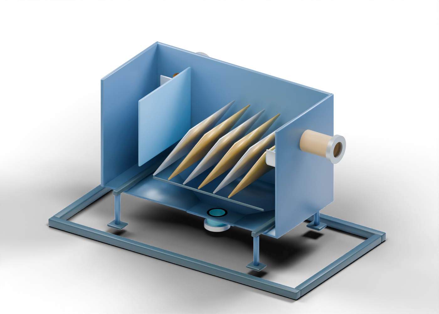 Invented static proportions illustrate roles, without measured separation or stream quality.
1. Already-diluted receiving region
Look for: Find the rear hollow feed neck and the divider beside the sheet region. The mixing equipment is upstream and outside this model.
This example receives froth already mixed with naphtha. Dilution and separation are different roles: the incoming material still needs separation, and the model supplies no dilution ratio or composition.
What has happened before the feed reaches this receiving region?
Compare the teaching explanations
- Upstream dilution; separation work remains — Yes. Follow the already-diluted feed toward the sheets and compare both outgoing responsibilities. Mixing equipment is outside the assembly.
- Adding naphtha has already removed every drop of water and all solids — Dilution changes the mixture's properties; it does not itself establish complete separation. The receiving region still leads into a separation role with two distinct outgoing boundaries.
- Upstream mixing has made finished vehicle fuel — Diluting froth does not manufacture diesel or gasoline. Keep bitumen processing separate from producing finished transport fuels.
2. Six separate inclined sheets
Look for: Compare the six individual sheets and open spaces between them. Rotate the cutaway to separate sheet surfaces from their support-location markers.
The inclined sheets illustrate a gravity-settling region in this naphtha-based example. Their number, angle and spacing are invented presentation choices, without a settling rate, separation efficiency or measured stream quality.
What can the visible sheet arrangement tell you?
Compare the teaching explanations
- Where to discuss the settling role, while performance remains unknown — Yes. Use the separate sheets to compare regions, then follow the upper and lower outlets. Their geometry does not quantify separation.
- The exact purity and recovery of the outgoing product — Open gaps and six sheets are geometry, not an assay or recovery measurement. Actual feed properties and process evidence would be needed for a performance claim.
- The equipment arrangement at every Alberta oil-sands mine — This is one generic naphtha-based example. Other approaches differ; Fort Hills describes a paraffinic process with counter-current settlers and solvent recovery.
3. Two outgoing responsibilities
Look for: Compare the right-side upper product neck and its collection region with the separate hollow outlet beneath the lower floor.
The upper branch continues toward bitumen processing and diluent recovery. The lower water-and-solids branch needs its own diluent-recovery and tailings handling. This lower branch is not a connection to the mining water-return exhibit.
Which handover keeps the two destinations distinct?
Compare the teaching explanations
- Further bitumen processing above; diluent and tailings handling below — Yes. Both boundaries leave work outside the model. Compare mining water reuse as a different lesson, rather than sending this lower stream directly into that exhibit.
- The lower stream is clean water ready to return directly to preparation or leave the site — Froth-treatment tailings need separate diluent-recovery and tailings handling. A hollow outlet gives no clean-water assay or release permission, and the scene supplies no direct connection to mining water return.
- The upper stream is finished diesel or gasoline ready for vehicles — This upper boundary identifies diluted-bitumen processing. It does not establish a finished transport fuel, product assay or receiving specification.
- Water and solids leave above; the bitumen product leaves below — Compare the two actual boundary groups: the upper side neck identifies the diluted-bitumen product direction; the lower floor and outlet identify froth-treatment tailings. Their different downstream responsibilities remain outside the model.
An original static naphtha-based gravity-separation example with invented proportions. It represents no named facility or universal process. Upstream dilution and downstream product, diluent and tailings equipment are outside the model; geometry supplies no measured performance, operating procedure or water-release decision.
Open the full froth-settler model
Follow water recovery
Compare the mixed feed, static solids pathway, lower tailings boundary and upper water boundary in the original thickener. Teaching checks and this self-reviewed handover add no field observations, operating credit or qualification.
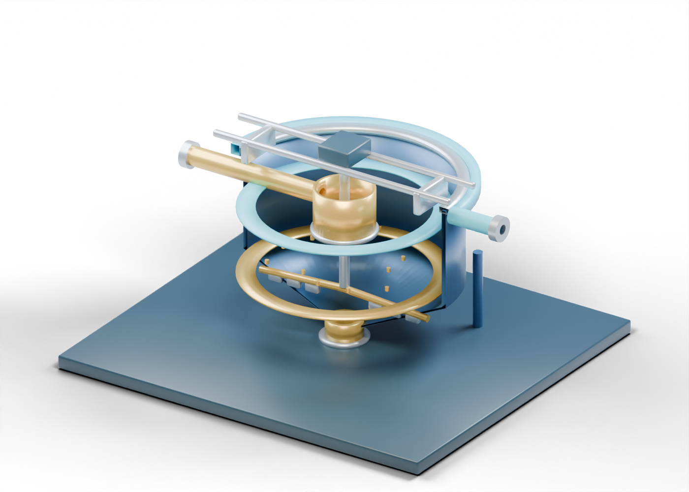 The region rings and settling markers are fixed teaching cues. Separate openings do not establish continuous assembled hydraulics, measured levels or water quality.
1. Mixed tailings feed
Look for: Compare the left-side feed neck, central feedwell and lower rim. They label the feed role; they do not demonstrate a continuous route through the assembled vessel.
Tailings arrive with water and mineral material together. Water recovery separates their destinations; the feed is not already the returning-water stream.
Why follow this feed boundary before comparing the outlets?
Compare the teaching explanations
- To identify the mixture before its water and solids take different paths — Yes. Start with the mixed feed, then follow both outgoing roles.
- Because the incoming material is already clean return water — The feed still contains mineral material. Compare it with the separate upper water boundary.
- Because this feedwell makes the finished bitumen product — This lesson follows water and tailings handling. Product treatment has a different role.
Process references: AER · State of Fluid Tailings Management, 2024 · AER · Tailings
2. Settling and solids pathway
Look for: Find the fixed particle markers above the lower arms and blades. Trace their illustrated solids role toward the centre and lower boundary.
Settling helps separate mineral particles from water. Finer material can remain suspended. The stationary rakes and markers illustrate a solids pathway, not a measured settling rate or complete removal of fines.
What is the useful distinction in this solids pathway?
Compare the teaching explanations
- Solids and recovered water follow different handling paths — Yes. Follow the lower solids boundary and the upper water boundary separately.
- Every fine particle has been removed because the markers are low — These fixed markers are teaching cues. Their position does not demonstrate complete removal of fines.
- The rakes illustrate all the water evaporating — Compare the separate water outlet. This concept illustrates water recovery, not evaporation of the whole feed.
Process references: AER · Tailings · AER · State of Fluid Tailings Management, 2024
3. Thickened tailings underflow
Look for: Follow the lower taper to its neck and open-end collar. The lower ring labels the thickened-material role rather than a measured solids concentration.
Water recovery leaves a thickened tailings stream for further treatment and placement. Thickening is an initial handling step; it does not establish that the material is dry or the land reclaimed.
What should a handover say about this lower stream?
Compare the teaching explanations
- Thickened tailings still need further handling — Yes. Keep the remaining tailings work visible alongside the water-reuse benefit.
- All water is gone and only dry solids remain — No moisture result is measured here. Thickened does not establish dry material.
- This boundary confirms the site is reclaimed — An initial handling step is different from reclamation. Follow the work beyond the vessel.
Process references: AER · State of Fluid Tailings Management, 2024 · AER · Tailings
4. Recovered process-water overflow
Look for: Compare the upper collection band and separate right-side water outlet with the lower solids boundary. Their individual openings do not demonstrate a continuous hydraulic path through the assembled vessel.
Recovered process water can return toward extraction and slurry preparation, reducing make-up needs. Water reuse does not establish drinking-water quality, release permission or the end of tailings management.
Which destination belongs in the water handover?
Compare the teaching explanations
- Back toward the process, while tailings management continues — Yes. Connect the returning water to preparation and keep the lower stream's remaining work separate.
- Outside the site, because the water ring looks clear — A clear-looking model cue is not water-quality evidence or permission to release process-affected water.
- Into the finished-fuel product stream — This upper boundary represents recovered process water. It is separate from bitumen-product treatment.
Process references: AER · Oil Sands Mining Water Use · AER · Tailings · AER · State of Fluid Tailings Management, 2024
Leave a useful water-recovery handover
In your own words, follow the mixture into the thickener, then explain where the recovered water and remaining tailings go. Add one question the model cannot answer before returning to your water note.
Review your own explanation
- Name the incoming water-and-mineral mixture before its destinations separate.
- Connect the lower solids pathway to underflow and further tailings handling.
- Follow recovered process water back toward preparation or extraction, without assuming make-up needs disappear.
- State one unknown, such as real water quality, settling performance or the permission needed for release, rather than presenting it as an observation.
Your narrative is self reviewed. The prompts do not grade it or assess operating competence.
No settling rate, solids concentration, water quality, reuse eligibility, release permission or matched plant design is established. Open the full thickener model
- AER · State of Fluid Tailings Management, 2024 — publisher published 2025-10-30; publisher modification date unverified; source checked 2026-10-05. Appendix 1 describes thickening as initial treatment, water reuse and further tailings handling. The reporting year is 2024; no operator-specific performance is claimed here.
- AER · Tailings — publication date unverified; publisher modification date unverified; source checked 2026-10-05
- AER · Oil Sands Mining Water Use — publication date unverified; publisher modification date unverified; source checked 2026-10-05. The page is labelled October 2025; an exact publisher modification date was not verified. This lesson uses qualitative water-reuse roles, not its sector figures.
7 field discoveries
Find your bearings
The small visitor road leads west to the mine and east to the process area. Heavy haul traffic uses its own road.
A surface mine and its extraction plant perform different jobs. This invented visitor route helps you follow the material between them.
Read the layers
The road descends beside stepped faces. Dark seams contrast with the lighter ground above them.
Surface mining exposes shallow oil-sands deposits after overlying material is removed. The terraces and layer colours here are illustrative.
At the mine floor
From beside the marker, compare your quad with the loader and large haul trucks on the separated work road.
The mine moves a mixture of sand, water and bitumen. Digging and hauling do not turn that mixture into finished fuel.
Follow a mined load
A haul route ends near the receiving area. The original hopper, stationary rolls, chute and mixing box illustrate preparation roles. The nearby conveyor is separate context, with a visible gap from the assembly.
Reducing and handling ore prepares it for a water-based extraction process. Watch for the separate roles of trucks, conveyors and pumps.
Read the separation branches
From the visitor point, face the primary vessel north of the road. Open its equipment study to compare the mixed-slurry inlet, upper froth outlet, middle recovery outlet and lower underflow boundary.
Primary separation sends different mixtures onward. Bitumen-rich froth needs more treatment; middlings have a further recovery role; the lower sand-and-water-rich branch needs tailings handling. The model does not measure purity or recovery.
Follow the other branch
The retention area and thickener are separate from the bitumen branch. Blue teaching cues return toward slurry preparation.
Tailings contain water and solids left after extraction. Recovering process water does not establish that it is drinking water or suitable for release.
Look beyond production
A small planted display sits beside stored soil and the boreal margin, away from the process vessels.
Land reclamation is a long-term part of a mine lifecycle. This small fictional display is context, not evidence of completed or certified reclamation.
Your visitor assignment
Follow mined ore from the pit to separated bitumen, then follow the water branch back toward extraction. Build your own visitor field guide: what enters each area, what changes, and where the material goes next.
- Distinguish a surface mine from an in-situ steam project.
- Follow ore preparation, slurry transport, extraction and froth treatment in a sensible order.
- Recognize that separated bitumen is not finished diesel or gasoline.
- Trace the separate water-and-tailings branch and explain why recycling does not finish reclamation.
1. The pit: begin with ore
Recover shallow oil-sands ore and send it toward preparation.
What enters: An oil-sands deposit close enough to the surface to mine
What leaves: A load containing mineral solids, bitumen and water
Look for: Compare a truck's faceted mixed-ore load with its open empty bed on the return leg. The load grows near the mine end and reduces near the receiving end as a qualitative flow illustration; the stationary loader does not dig or tip. The material still contains minerals, water and bitumen, rather than separated crude oil.
Your field note: What is in this load, and what tells you this is a surface mine rather than a SAGD well site?
What are you following out of the pit?
The load is oil-sands ore: bitumen travels with sand, clay or other minerals and water. Separation happens downstream.
Which recovery method matches the visible pit and ore haul route?
This route excavates ore and takes it to an extraction facility. SAGD instead heats a deeper reservoir and produces fluids through wells.
2. Ore preparation: change the size
Break large ore lumps into feed that the next stages can handle.
What enters: Mined ore with large lumps
What leaves: Prepared ore moving toward slurry preparation
Look for: Watch the loaded outbound trucks and empty returns, then locate the labelled mixed-ore receiving buffer. In the preparation exhibit, follow smaller mixed-ore cues down the open chute into the mixing-box region; the rolls remain stationary. The neighbouring conveyor carries mixed-ore cues into its own open receiving tray. It is a separate handling display, with a visible gap from the exhibit and nearby vessel. Motion and fragment sizes are qualitative, not throughput, tonnage or a tipping procedure.
Your field note: What changed here, and what still needs to be separated?
What does the crusher change in this route?
Ore preparation reduces large lumps. This physical preparation is different from separating bitumen or changing its hydrocarbon molecules.
Where should this prepared ore go next?
Prepared ore moves toward mixing with process water so the slurry can travel to extraction.
3. Slurry: follow the pipeline
Mix prepared ore with process water for transport and conditioning before separation.
What enters: Prepared ore and process water
What leaves: A water-based slurry carrying bitumen and mineral solids to extraction
Look for: Trace the water line into slurry preparation and the large outgoing line toward the separation vessel. A second water line returns from the recovery area you will visit later.
Your field note: What does the outgoing pipeline carry, and why can the returning water line matter?
What is in the slurry line before extraction?
The pipeline carries water together with the prepared ore constituents. The bitumen has not yet become a cleaned product stream.
What can the return-water line supply here?
Recovered process water can be reused in extraction. Recycling reduces demand for make-up water, but does not mean every water requirement disappears.
4. Extraction: one feed, two routes
Separate a bitumen-rich froth from much of the mineral material and water.
What enters: Conditioned oil-sands slurry
What leaves: Bitumen-rich froth toward treatment; a separate water-and-solids tailings route
Look for: Follow the upper froth outlet toward froth treatment, then find the separate lower tailings route. In the simplified vessel, bitumen-rich froth collects above while much of the mineral material leaves with water below.
Your field note: Name both outgoing routes. Why is the top stream still called froth rather than finished fuel?
What should the upper froth route carry onward?
The bitumen-rich froth still contains water and mineral particles. It goes onward for froth treatment.
What happens to the other material from this feed?
Much of the mineral solids and water follows a separate tailings-management route, including recovery of water for reuse. The simplified picture does not imply complete recovery of all bitumen.
5. Froth treatment: clean the bitumen stream
Remove more water and fine mineral material from the bitumen-rich froth.
What enters: Bitumen-rich froth from extraction
What leaves: A cleaner bitumen stream for subsequent transport or processing
Look for: The bitumen-rich route continues past the cleanup equipment toward a product outlet. Water and solids removed during cleanup join management routes; they do not become finished fuel.
Your field note: What has this area removed, and what further processing is still distinct from this cleanup?
What is the job of this stage?
Froth treatment recovers bitumen from the water-and-solids mixture produced by extraction. The cleanup methods vary by project.
Which description fits the product leaving this simplified route?
The recovered product is bitumen, possibly prepared with diluent for transport. Upgrading and refining are separate; not every mine has the same downstream arrangement.
6. Water and tailings: follow the other branch
Recover process water for reuse while managing the remaining tailings.
What enters: Water, mineral solids and residual material from separation routes
What leaves: Recovered process water toward extraction; tailings requiring continued management
Look for: You are following a branch from extraction, not sending cleaned bitumen through a pond. Trace recovered water back toward slurry preparation. The solids remaining here need management beyond this visit.
Your field note: Where can recovered process water go, and what has recycling not solved on its own?
Which destination matches the recovered-water line?
The process-water route returns water for reuse in extraction. Reuse is different from declaring that water suitable for unrestricted environmental release.
Does recovering water finish the tailings and land-reclamation work?
Recovering water leaves tailings to manage. Fine particles can remain suspended, and reclamation needs ongoing planning, treatment, monitoring and verification.
Put the routes together
The main route is mined ore → ore preparation → slurry preparation → extraction → froth treatment. Extraction also splits off a water-and-solids tailings route; recovered process water can return toward slurry preparation. The cleaned hydrocarbon product is bitumen, with transport preparation, upgrading or refining beyond this simplified visit.
A different recovery setting
What changes if the deposit is too deep to mine?
An in-situ recovery route such as SAGD may be used instead. Do not carry this pit–crusher–slurry diagram into an underground steam project: its recovery equipment and material routes differ.
Beyond the visitor route
The reclamation area is a reminder of work beyond bitumen recovery. A green patch in this illustrative scene does not establish that an actual mine or tailings area has met reclamation requirements.
Scope and sources
This is a simplified, invented mine visit. The layout, visitor route and equipment proportions are illustrative. Parallel circuits, utility systems and many treatment stages are omitted. No real operating values, vehicle procedures or site qualification are taught.
Look inside primary separation · Take a focused operator round