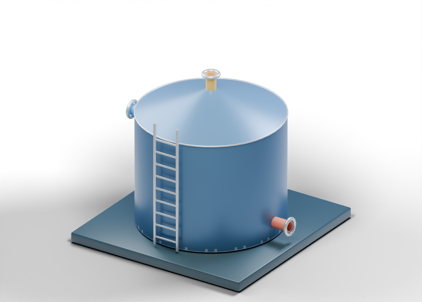
Base frame
Illustrative support frame; foundations and structural design vary.
Tank wall
Generic atmospheric tank wall with geometric fill, withdrawal and manway openings. Thickness and dimensions are illustrative.
Tank floor
Generic bottom plate.
Fixed roof
Double-surface fixed cone roof with an open vent penetration. Framing, weld design, loads and emergency venting are outside this model.
Roof-to-wall joint
Illustrative joint location; no weld section or qualified connection.
Bottom-to-wall joint
Illustrative joint location; no weld design or inspection acceptance criteria.
Illustrative liquid
Static teaching inventory; not a measured level, capacity or product specification.
Vent connection
Open geometric vent connection only. Normal and emergency vent devices, vapour handling, sizing and discharge destinations are omitted; this opening is not a complete venting system.
Vent connection flange
Illustrative flange ring, with no rated facing or bolt specification.
Vent connection fastener 1
Generic fastener position. Quantity and size do not specify a rated connection.
Vent connection fastener 2
Generic fastener position. Quantity and size do not specify a rated connection.
Vent connection fastener 3
Generic fastener position. Quantity and size do not specify a rated connection.
Vent connection fastener 4
Generic fastener position. Quantity and size do not specify a rated connection.
Vent connection fastener 5
Generic fastener position. Quantity and size do not specify a rated connection.
Vent connection fastener 6
Generic fastener position. Quantity and size do not specify a rated connection.
Vent connection fastener 7
Generic fastener position. Quantity and size do not specify a rated connection.
Vent connection fastener 8
Generic fastener position. Quantity and size do not specify a rated connection.
Fill connection
Hollow generic connection with illustrative wall thickness. Welds, facing and pressure ratings are not specified.
Fill connection flange
Illustrative flange ring, with no rated facing or bolt specification.
Fill connection fastener 1
Generic fastener position. Quantity and size do not specify a rated connection.
Fill connection fastener 2
Generic fastener position. Quantity and size do not specify a rated connection.
Fill connection fastener 3
Generic fastener position. Quantity and size do not specify a rated connection.
Fill connection fastener 4
Generic fastener position. Quantity and size do not specify a rated connection.
Fill connection fastener 5
Generic fastener position. Quantity and size do not specify a rated connection.
Fill connection fastener 6
Generic fastener position. Quantity and size do not specify a rated connection.
Fill connection fastener 7
Generic fastener position. Quantity and size do not specify a rated connection.
Fill connection fastener 8
Generic fastener position. Quantity and size do not specify a rated connection.
Withdrawal connection
Hollow generic connection with illustrative wall thickness. Welds, facing and pressure ratings are not specified.
Withdrawal connection flange
Illustrative flange ring, with no rated facing or bolt specification.
Withdrawal connection fastener 1
Generic fastener position. Quantity and size do not specify a rated connection.
Withdrawal connection fastener 2
Generic fastener position. Quantity and size do not specify a rated connection.
Withdrawal connection fastener 3
Generic fastener position. Quantity and size do not specify a rated connection.
Withdrawal connection fastener 4
Generic fastener position. Quantity and size do not specify a rated connection.
Withdrawal connection fastener 5
Generic fastener position. Quantity and size do not specify a rated connection.
Withdrawal connection fastener 6
Generic fastener position. Quantity and size do not specify a rated connection.
Withdrawal connection fastener 7
Generic fastener position. Quantity and size do not specify a rated connection.
Withdrawal connection fastener 8
Generic fastener position. Quantity and size do not specify a rated connection.
Manway neck
Hollow generic connection with illustrative wall thickness. Welds, facing and pressure ratings are not specified.
Manway neck flange
Illustrative flange ring, with no rated facing or bolt specification.
Manway neck fastener 1
Generic fastener position. Quantity and size do not specify a rated connection.
Manway neck fastener 2
Generic fastener position. Quantity and size do not specify a rated connection.
Manway neck fastener 3
Generic fastener position. Quantity and size do not specify a rated connection.
Manway neck fastener 4
Generic fastener position. Quantity and size do not specify a rated connection.
Manway neck fastener 5
Generic fastener position. Quantity and size do not specify a rated connection.
Manway neck fastener 6
Generic fastener position. Quantity and size do not specify a rated connection.
Manway neck fastener 7
Generic fastener position. Quantity and size do not specify a rated connection.
Manway neck fastener 8
Generic fastener position. Quantity and size do not specify a rated connection.
Manway gasket
Conceptual gasket location between neck flange and cover; material, compression and leakage performance are unspecified.
Manway cover
Closed removable-cover concept. Reveal internals hides this cover for learning; the explorer is not an entry or opening procedure.
Ladder rail -0.3
Illustrative access ladder; safety systems and required dimensions omitted.
Ladder rail 0.3
Illustrative access ladder; safety systems and required dimensions omitted.
Ladder rung 0.5
Schematic ladder rung.
Ladder rung 0.8
Schematic ladder rung.
Ladder rung 1.1
Schematic ladder rung.
Ladder rung 1.4
Schematic ladder rung.
Ladder rung 1.7
Schematic ladder rung.
Ladder rung 2
Schematic ladder rung.
Ladder rung 2.3
Schematic ladder rung.
Ladder rung 2.6
Schematic ladder rung.
Ladder rung 2.9
Schematic ladder rung.