No components match your search. Try a shorter part name.
Open display frame front rail
An original open-centre presentation frame leaves the lower outlet visible. No structural or foundation design. Original static teaching geometry with invented proportions. No selected product, process performance, structural or operating qualification.
Open display frame rear rail
An original open-centre presentation frame leaves the lower outlet visible. No structural or foundation design. Original static teaching geometry with invented proportions. No selected product, process performance, structural or operating qualification.
Open display frame left rail
An original open-centre presentation frame leaves the lower outlet visible. No structural or foundation design. Original static teaching geometry with invented proportions. No selected product, process performance, structural or operating qualification.
Open display frame right rail
An original open-centre presentation frame leaves the lower outlet visible. No structural or foundation design. Original static teaching geometry with invented proportions. No selected product, process performance, structural or operating qualification.
Complete removable front enclosure
The retained complete facing wall can be removed for study. This is a presentation section, not a safe access state. Original static teaching geometry with invented proportions. No selected product, process performance, structural or operating qualification.
Complete rear enclosure with feed bore
Complete rear wall containing a real feed opening into the distinct left-side receiving chamber. Original static teaching geometry with invented proportions. No selected product, process performance, structural or operating qualification.
Complete left enclosure
Retained left wall around the invented receiving chamber; no pressure containment or manufactured joint. Original static teaching geometry with invented proportions. No selected product, process performance, structural or operating qualification.
Complete right enclosure with product bore
Retained right wall with a real separate diluted-bitumen boundary opening. Original static teaching geometry with invented proportions. No selected product, process performance, structural or operating qualification.
Complete removable roof
The complete display roof can be removed for study. Venting, protection, access and fabrication are outside this illustration. Original static teaching geometry with invented proportions. No selected product, process performance, structural or operating qualification.
Complete front lower collection wall
A complete inclined wall identifies lower water-and-solids collection. The slope is not a settling, solids-handling or structural specification. Original static teaching geometry with invented proportions. No selected product, process performance, structural or operating qualification.
Complete right lower collection wall
A complete inclined wall identifies lower water-and-solids collection. The slope is not a settling, solids-handling or structural specification. Original static teaching geometry with invented proportions. No selected product, process performance, structural or operating qualification.
Complete back lower collection wall
A complete inclined wall identifies lower water-and-solids collection. The slope is not a settling, solids-handling or structural specification. Original static teaching geometry with invented proportions. No selected product, process performance, structural or operating qualification.
Complete left lower collection wall
A complete inclined wall identifies lower water-and-solids collection. The slope is not a settling, solids-handling or structural specification. Original static teaching geometry with invented proportions. No selected product, process performance, structural or operating qualification.
Complete bored lower collection floor
Retained lowest floor with an actual underflow aperture. A visible opening does not establish drainage, removal efficiency or permissible disposal. Original static teaching geometry with invented proportions. No selected product, process performance, structural or operating qualification.
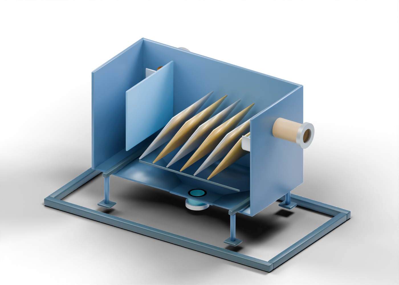
Open diluted-froth feed neck
Feed boundary for froth already mixed with naphtha upstream. The mixing/dilution equipment and conditions are outside this model. Original static teaching geometry with invented proportions. No selected product, process performance, structural or operating qualification.
Feed open-end collar
Hollow feed-boundary marker. It is not a rated flange, valve or engineered connection. Original static teaching geometry with invented proportions. No selected product, process performance, structural or operating qualification.
Open diluted-bitumen product neck
Separate upper product boundary toward further processing and diluent recovery. No assay, specification, purity or finished transport fuel is established. Original static teaching geometry with invented proportions. No selected product, process performance, structural or operating qualification.
Product open-end collar
Open product-side boundary marker, without a custody-transfer or pipeline-quality claim. Original static teaching geometry with invented proportions. No selected product, process performance, structural or operating qualification.
Open froth-treatment-tailings neck
Distinct lower water-and-solids boundary. Residual hydrocarbons and diluent handling remain questions for downstream treatment and containment. Original static teaching geometry with invented proportions. No selected product, process performance, structural or operating qualification.
Tailings open-end collar
Hollow lower boundary marker; the model does not prove drinking-water quality, release approval or completed reclamation. Original static teaching geometry with invented proportions. No selected product, process performance, structural or operating qualification.
Receiving-chamber divider
A distinct original divider identifies the receiving side and leaves a lower geometric gap. No hydraulic distribution or process routing is validated. Original static teaching geometry with invented proportions. No selected product, process performance, structural or operating qualification.
Feed deflection marker
Separate illustrative deflector before the plate region. Its shape does not establish inlet momentum, distribution or emulsion behaviour. Original static teaching geometry with invented proportions. No selected product, process performance, structural or operating qualification.
Inclined settling plate 1
One of six independently selectable inclined sheets. The visible gaps illustrate separate settling surfaces, not selected plate dimensions, packing density or a separation result. Original static teaching geometry with invented proportions. No selected product, process performance, structural or operating qualification.
Inclined settling plate 2
One of six independently selectable inclined sheets. The visible gaps illustrate separate settling surfaces, not selected plate dimensions, packing density or a separation result. Original static teaching geometry with invented proportions. No selected product, process performance, structural or operating qualification.
Inclined settling plate 3
One of six independently selectable inclined sheets. The visible gaps illustrate separate settling surfaces, not selected plate dimensions, packing density or a separation result. Original static teaching geometry with invented proportions. No selected product, process performance, structural or operating qualification.
Inclined settling plate 4
One of six independently selectable inclined sheets. The visible gaps illustrate separate settling surfaces, not selected plate dimensions, packing density or a separation result. Original static teaching geometry with invented proportions. No selected product, process performance, structural or operating qualification.
Inclined settling plate 5
One of six independently selectable inclined sheets. The visible gaps illustrate separate settling surfaces, not selected plate dimensions, packing density or a separation result. Original static teaching geometry with invented proportions. No selected product, process performance, structural or operating qualification.
Inclined settling plate 6
One of six independently selectable inclined sheets. The visible gaps illustrate separate settling surfaces, not selected plate dimensions, packing density or a separation result. Original static teaching geometry with invented proportions. No selected product, process performance, structural or operating qualification.
Plate support location 1
Separate support-location cue beneath the lower sheet ends; no attachment, loading or fabrication is specified. Original static teaching geometry with invented proportions. No selected product, process performance, structural or operating qualification.
Plate support location 2
Separate support-location cue beneath the lower sheet ends; no attachment, loading or fabrication is specified. Original static teaching geometry with invented proportions. No selected product, process performance, structural or operating qualification.
Product collection trough floor
A distinct collection-region floor beside the upper product boundary. Its elevation does not show a measured operating interface. Original static teaching geometry with invented proportions. No selected product, process performance, structural or operating qualification.
Product collection inner edge
An invented lower edge separates the collection region from the plate display. No weir loading or level control is established. Original static teaching geometry with invented proportions. No selected product, process performance, structural or operating qualification.
Product collection end wall 1
A retained end-location panel for the independent upper collection role; no vessel performance or sealing claim. Original static teaching geometry with invented proportions. No selected product, process performance, structural or operating qualification.
Product collection end wall 2
A retained end-location panel for the independent upper collection role; no vessel performance or sealing claim. Original static teaching geometry with invented proportions. No selected product, process performance, structural or operating qualification.
Display transverse beam 1
Invented display support beam. This is no structural, foundation or access design. Original static teaching geometry with invented proportions. No selected product, process performance, structural or operating qualification.
Display support leg 1.1
Presentation support only; no load, restraint, maintenance or safe access is demonstrated. Original static teaching geometry with invented proportions. No selected product, process performance, structural or operating qualification.
Display support foot 1.1
Separate foot with one geometric anchor-position bore, without an anchor or structural qualification. Original static teaching geometry with invented proportions. No selected product, process performance, structural or operating qualification.
Display support leg 1.2
Presentation support only; no load, restraint, maintenance or safe access is demonstrated. Original static teaching geometry with invented proportions. No selected product, process performance, structural or operating qualification.
Display support foot 1.2
Separate foot with one geometric anchor-position bore, without an anchor or structural qualification. Original static teaching geometry with invented proportions. No selected product, process performance, structural or operating qualification.
Display transverse beam 2
Invented display support beam. This is no structural, foundation or access design. Original static teaching geometry with invented proportions. No selected product, process performance, structural or operating qualification.
Display support leg 2.1
Presentation support only; no load, restraint, maintenance or safe access is demonstrated. Original static teaching geometry with invented proportions. No selected product, process performance, structural or operating qualification.
Display support foot 2.1
Separate foot with one geometric anchor-position bore, without an anchor or structural qualification. Original static teaching geometry with invented proportions. No selected product, process performance, structural or operating qualification.
Display support leg 2.2
Presentation support only; no load, restraint, maintenance or safe access is demonstrated. Original static teaching geometry with invented proportions. No selected product, process performance, structural or operating qualification.
Display support foot 2.2
Separate foot with one geometric anchor-position bore, without an anchor or structural qualification. Original static teaching geometry with invented proportions. No selected product, process performance, structural or operating qualification.