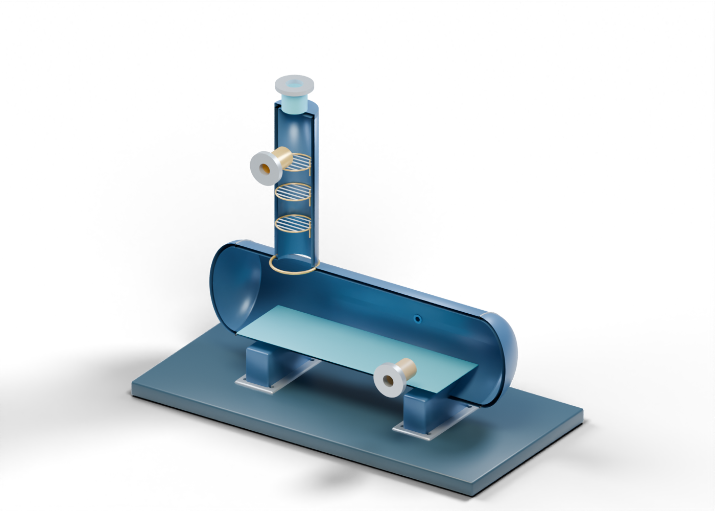
Base frame
Illustrative support frame; foundations and structural design vary.
Reboiler hollow kettle wall
Actual hollow horizontal vessel; no code, duty or heat-transfer design. Invented static teaching geometry; no thermal, process, pressure, emissions, burner or service qualification.
Reboiler dished head -1
Generic double-surface dished closure. Shape and thickness are illustrative, with no code qualification.
Kettle head seam -1
Illustrative closure location only. Invented static teaching geometry; no thermal, process, pressure, emissions, burner or service qualification.
Reboiler dished head 1
Generic double-surface dished closure. Shape and thickness are illustrative, with no code qualification.
Kettle head seam 1
Illustrative closure location only. Invented static teaching geometry; no thermal, process, pressure, emissions, burner or service qualification.
Kettle saddle 1
Illustrative saddle; no load or foundation design. Invented static teaching geometry; no thermal, process, pressure, emissions, burner or service qualification.
Kettle saddle foot 1
Separate support attachment marker. Invented static teaching geometry; no thermal, process, pressure, emissions, burner or service qualification.
Kettle saddle 2
Illustrative saddle; no load or foundation design. Invented static teaching geometry; no thermal, process, pressure, emissions, burner or service qualification.
Kettle saddle foot 2
Separate support attachment marker. Invented static teaching geometry; no thermal, process, pressure, emissions, burner or service qualification.
Still hollow column wall
Vertical still-region enclosure open toward the kettle; no selected contacting internals. Invented static teaching geometry; no thermal, process, pressure, emissions, burner or service qualification.
Still-to-kettle location ring
Joint location only; no weld, seal or structural qualification. Invented static teaching geometry; no thermal, process, pressure, emissions, burner or service qualification.
Still top plate
Illustrative top closure with actual overhead opening. Invented static teaching geometry; no thermal, process, pressure, emissions, burner or service qualification.
Water-vapor overhead hollow neck
Open water-vapor boundary; no condenser, vent destination or emissions result. Invented static teaching geometry; no thermal, process, pressure, emissions, burner or service qualification.
Water-vapor overhead bored termination
Separate overhead termination; no relief or environmental design. Invented static teaching geometry; no thermal, process, pressure, emissions, burner or service qualification.
Rich-glycol feed hollow neck
Open rich-glycol feed teaching boundary. Invented static teaching geometry; no thermal, process, pressure, emissions, burner or service qualification.
Rich-glycol feed bored termination
Separate annular termination; no selected flange or joint. Invented static teaching geometry; no thermal, process, pressure, emissions, burner or service qualification.
Lean-glycol outlet hollow neck
Open lean-glycol outlet teaching boundary. Invented static teaching geometry; no thermal, process, pressure, emissions, burner or service qualification.
Lean-glycol outlet bored termination
Separate annular termination; no selected flange or joint. Invented static teaching geometry; no thermal, process, pressure, emissions, burner or service qualification.
Illustrative instrument tap hollow neck
Open illustrative instrument tap teaching boundary. Invented static teaching geometry; no thermal, process, pressure, emissions, burner or service qualification.
Illustrative instrument tap bored termination
Separate annular termination; no selected flange or joint. Invented static teaching geometry; no thermal, process, pressure, emissions, burner or service qualification.
Still region 1 perimeter
Open contacting-region location, not a selected tray or packing. Invented static teaching geometry; no thermal, process, pressure, emissions, burner or service qualification.
Still region 1 crossbar 1
Separate open-grid marker; no hydraulics, reflux or efficiency claim. Invented static teaching geometry; no thermal, process, pressure, emissions, burner or service qualification.
Still region 1 crossbar 2
Separate open-grid marker; no hydraulics, reflux or efficiency claim. Invented static teaching geometry; no thermal, process, pressure, emissions, burner or service qualification.
Still region 1 crossbar 3
Separate open-grid marker; no hydraulics, reflux or efficiency claim. Invented static teaching geometry; no thermal, process, pressure, emissions, burner or service qualification.
Still region 1 crossbar 4
Separate open-grid marker; no hydraulics, reflux or efficiency claim. Invented static teaching geometry; no thermal, process, pressure, emissions, burner or service qualification.
Still region 1 crossbar 5
Separate open-grid marker; no hydraulics, reflux or efficiency claim. Invented static teaching geometry; no thermal, process, pressure, emissions, burner or service qualification.
Still region 2 perimeter
Open contacting-region location, not a selected tray or packing. Invented static teaching geometry; no thermal, process, pressure, emissions, burner or service qualification.
Still region 2 crossbar 1
Separate open-grid marker; no hydraulics, reflux or efficiency claim. Invented static teaching geometry; no thermal, process, pressure, emissions, burner or service qualification.
Still region 2 crossbar 2
Separate open-grid marker; no hydraulics, reflux or efficiency claim. Invented static teaching geometry; no thermal, process, pressure, emissions, burner or service qualification.
Still region 2 crossbar 3
Separate open-grid marker; no hydraulics, reflux or efficiency claim. Invented static teaching geometry; no thermal, process, pressure, emissions, burner or service qualification.
Still region 2 crossbar 4
Separate open-grid marker; no hydraulics, reflux or efficiency claim. Invented static teaching geometry; no thermal, process, pressure, emissions, burner or service qualification.
Still region 2 crossbar 5
Separate open-grid marker; no hydraulics, reflux or efficiency claim. Invented static teaching geometry; no thermal, process, pressure, emissions, burner or service qualification.
Still region 3 perimeter
Open contacting-region location, not a selected tray or packing. Invented static teaching geometry; no thermal, process, pressure, emissions, burner or service qualification.
Still region 3 crossbar 1
Separate open-grid marker; no hydraulics, reflux or efficiency claim. Invented static teaching geometry; no thermal, process, pressure, emissions, burner or service qualification.
Still region 3 crossbar 2
Separate open-grid marker; no hydraulics, reflux or efficiency claim. Invented static teaching geometry; no thermal, process, pressure, emissions, burner or service qualification.
Still region 3 crossbar 3
Separate open-grid marker; no hydraulics, reflux or efficiency claim. Invented static teaching geometry; no thermal, process, pressure, emissions, burner or service qualification.
Still region 3 crossbar 4
Separate open-grid marker; no hydraulics, reflux or efficiency claim. Invented static teaching geometry; no thermal, process, pressure, emissions, burner or service qualification.
Still region 3 crossbar 5
Separate open-grid marker; no hydraulics, reflux or efficiency claim. Invented static teaching geometry; no thermal, process, pressure, emissions, burner or service qualification.
Still downflow location 1
Orientation marker only; no validated flow or liquid seal. Invented static teaching geometry; no thermal, process, pressure, emissions, burner or service qualification.
Still downflow location 2
Orientation marker only; no validated flow or liquid seal. Invented static teaching geometry; no thermal, process, pressure, emissions, burner or service qualification.
Still downflow location 3
Orientation marker only; no validated flow or liquid seal. Invented static teaching geometry; no thermal, process, pressure, emissions, burner or service qualification.
Illustrative reboiler liquid region
Static region marker, not measured liquid level or process inventory. Invented static teaching geometry; no thermal, process, pressure, emissions, burner or service qualification.
Heat-transfer region marker 1
Explanatory position marker only; no firing, heat duty or heating-surface design. Invented static teaching geometry; no thermal, process, pressure, emissions, burner or service qualification.
Heat-transfer region marker 2
Explanatory position marker only; no firing, heat duty or heating-surface design. Invented static teaching geometry; no thermal, process, pressure, emissions, burner or service qualification.
Heat-transfer region marker 3
Explanatory position marker only; no firing, heat duty or heating-surface design. Invented static teaching geometry; no thermal, process, pressure, emissions, burner or service qualification.
Heat-region end marker 1
End of schematic heat region; no through-wall connection. Invented static teaching geometry; no thermal, process, pressure, emissions, burner or service qualification.
Heat-region end marker 2
End of schematic heat region; no through-wall connection. Invented static teaching geometry; no thermal, process, pressure, emissions, burner or service qualification.