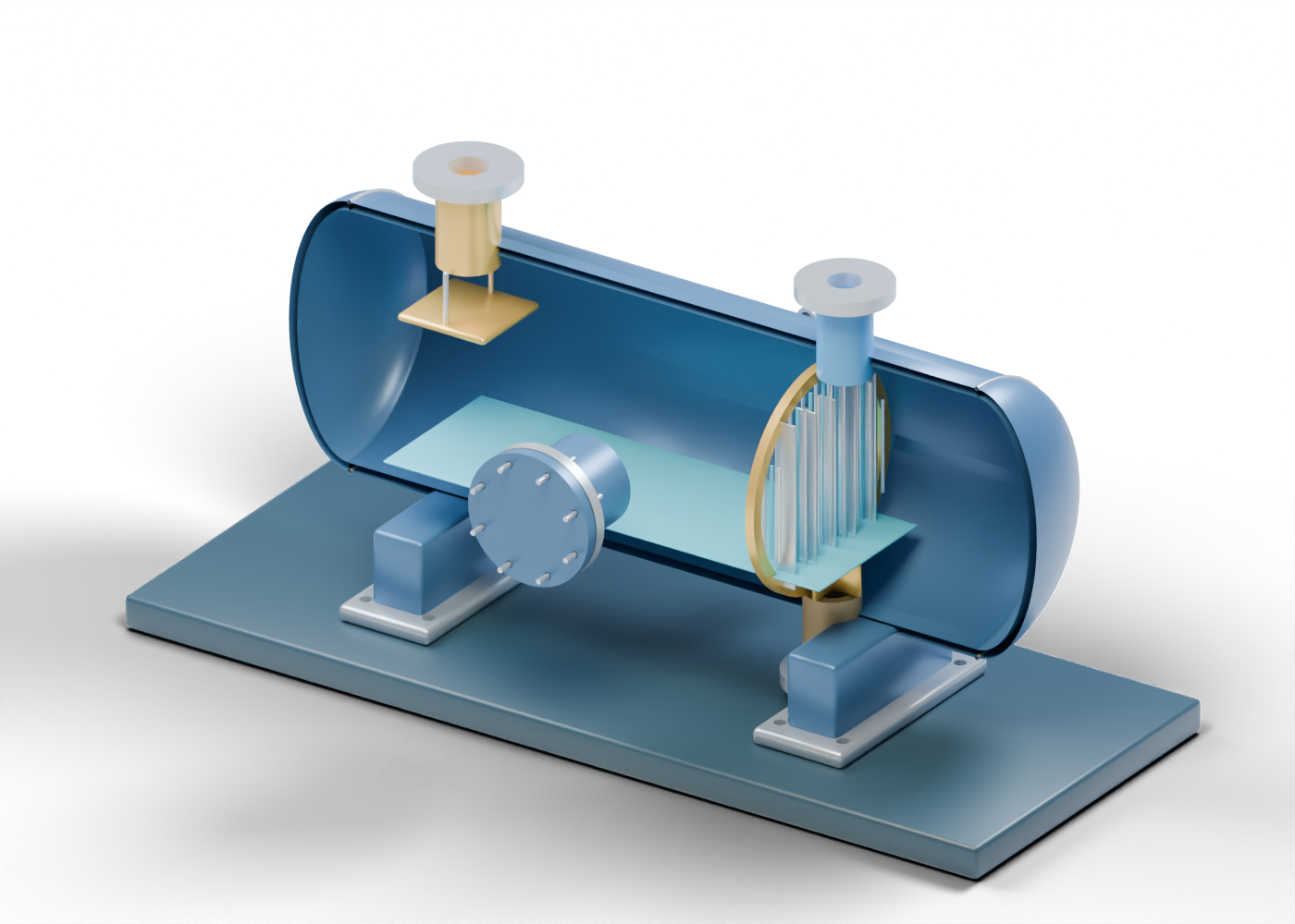
Flash-tank hollow vessel wall
Open-ended horizontal enclosure with three actual boundary holes. Original invented static geometry; no chemistry, phase split, emissions, pressure, level, materials, safe service or equipment rating.
Flash-tank dished head -1
Generic double-surface dished closure. Shape and thickness are illustrative, with no code qualification.
Head seam marker -1
Separate shell/head location; no weld or inspection evidence. Original invented static geometry; no chemistry, phase split, emissions, pressure, level, materials, safe service or equipment rating.
Flash-tank dished head 1
Generic double-surface dished closure. Shape and thickness are illustrative, with no code qualification.
Head seam marker 1
Separate shell/head location; no weld or inspection evidence. Original invented static geometry; no chemistry, phase split, emissions, pressure, level, materials, safe service or equipment rating.
Base frame
Illustrative support frame; foundations and structural design vary.
Saddle 1
Illustrative saddle envelope without matched curvature, load or anchorage. Original invented static geometry; no chemistry, phase split, emissions, pressure, level, materials, safe service or equipment rating.
Saddle foot 1
Separate bored attachment-location marker. Original invented static geometry; no chemistry, phase split, emissions, pressure, level, materials, safe service or equipment rating.
Saddle 2
Illustrative saddle envelope without matched curvature, load or anchorage. Original invented static geometry; no chemistry, phase split, emissions, pressure, level, materials, safe service or equipment rating.
Saddle foot 2
Separate bored attachment-location marker. Original invented static geometry; no chemistry, phase split, emissions, pressure, level, materials, safe service or equipment rating.
Rich-glycol inlet hollow neck
Open, independent rich-glycol inlet boundary. Original invented static geometry; no chemistry, phase split, emissions, pressure, level, materials, safe service or equipment rating.
Rich-glycol inlet bored flange
Separate annular flange marker; no pressure class, facing or bolted-joint qualification. Original invented static geometry; no chemistry, phase split, emissions, pressure, level, materials, safe service or equipment rating.
Flash-gas outlet hollow neck
Open, independent flash-gas outlet boundary. Original invented static geometry; no chemistry, phase split, emissions, pressure, level, materials, safe service or equipment rating.
Flash-gas outlet bored flange
Separate annular flange marker; no pressure class, facing or bolted-joint qualification. Original invented static geometry; no chemistry, phase split, emissions, pressure, level, materials, safe service or equipment rating.
Rich-glycol outlet hollow neck
Open, independent rich-glycol outlet boundary. Original invented static geometry; no chemistry, phase split, emissions, pressure, level, materials, safe service or equipment rating.
Rich-glycol outlet bored flange
Separate annular flange marker; no pressure class, facing or bolted-joint qualification. Original invented static geometry; no chemistry, phase split, emissions, pressure, level, materials, safe service or equipment rating.
Closed access hollow neck
Open, independent closed access boundary. Original invented static geometry; no chemistry, phase split, emissions, pressure, level, materials, safe service or equipment rating.
Closed access bored flange
Separate annular flange marker; no pressure class, facing or bolted-joint qualification. Original invented static geometry; no chemistry, phase split, emissions, pressure, level, materials, safe service or equipment rating.
Closed access gasket location
Separate gasket-location marker; no material or seal result. Original invented static geometry; no chemistry, phase split, emissions, pressure, level, materials, safe service or equipment rating.
Closed access solid cover
Solid closed cover; no vessel-opening or entry procedure. Original invented static geometry; no chemistry, phase split, emissions, pressure, level, materials, safe service or equipment rating.
Closed access smooth stud 1
Separate smooth joint marker; no thread, preload or opening instruction. Original invented static geometry; no chemistry, phase split, emissions, pressure, level, materials, safe service or equipment rating.
Closed access smooth stud 2
Separate smooth joint marker; no thread, preload or opening instruction. Original invented static geometry; no chemistry, phase split, emissions, pressure, level, materials, safe service or equipment rating.
Closed access smooth stud 3
Separate smooth joint marker; no thread, preload or opening instruction. Original invented static geometry; no chemistry, phase split, emissions, pressure, level, materials, safe service or equipment rating.
Closed access smooth stud 4
Separate smooth joint marker; no thread, preload or opening instruction. Original invented static geometry; no chemistry, phase split, emissions, pressure, level, materials, safe service or equipment rating.
Closed access smooth stud 5
Separate smooth joint marker; no thread, preload or opening instruction. Original invented static geometry; no chemistry, phase split, emissions, pressure, level, materials, safe service or equipment rating.
Closed access smooth stud 6
Separate smooth joint marker; no thread, preload or opening instruction. Original invented static geometry; no chemistry, phase split, emissions, pressure, level, materials, safe service or equipment rating.
Closed access smooth stud 7
Separate smooth joint marker; no thread, preload or opening instruction. Original invented static geometry; no chemistry, phase split, emissions, pressure, level, materials, safe service or equipment rating.
Closed access smooth stud 8
Separate smooth joint marker; no thread, preload or opening instruction. Original invented static geometry; no chemistry, phase split, emissions, pressure, level, materials, safe service or equipment rating.
Inlet impact diverter
Separate impact/diversion location beneath the inlet. No impingement, erosion or phase-separation result. Original invented static geometry; no chemistry, phase split, emissions, pressure, level, materials, safe service or equipment rating.
Diverter support 1
Illustrative diverter support; no mechanical load qualification. Original invented static geometry; no chemistry, phase split, emissions, pressure, level, materials, safe service or equipment rating.
Diverter support 2
Illustrative diverter support; no mechanical load qualification. Original invented static geometry; no chemistry, phase split, emissions, pressure, level, materials, safe service or equipment rating.
Open mist-region support ring
Location marker for an open mist region, not a specified mist eliminator or capture result. Original invented static geometry; no chemistry, phase split, emissions, pressure, level, materials, safe service or equipment rating.
Mist lattice layer 1 member 1
Open straight lattice member, not media design, drainage or removal efficiency. Original invented static geometry; no chemistry, phase split, emissions, pressure, level, materials, safe service or equipment rating.
Mist lattice layer 1 member 2
Open straight lattice member, not media design, drainage or removal efficiency. Original invented static geometry; no chemistry, phase split, emissions, pressure, level, materials, safe service or equipment rating.
Mist lattice layer 1 member 3
Open straight lattice member, not media design, drainage or removal efficiency. Original invented static geometry; no chemistry, phase split, emissions, pressure, level, materials, safe service or equipment rating.
Mist lattice layer 1 member 4
Open straight lattice member, not media design, drainage or removal efficiency. Original invented static geometry; no chemistry, phase split, emissions, pressure, level, materials, safe service or equipment rating.
Mist lattice layer 1 member 5
Open straight lattice member, not media design, drainage or removal efficiency. Original invented static geometry; no chemistry, phase split, emissions, pressure, level, materials, safe service or equipment rating.
Mist lattice layer 1 member 6
Open straight lattice member, not media design, drainage or removal efficiency. Original invented static geometry; no chemistry, phase split, emissions, pressure, level, materials, safe service or equipment rating.
Mist lattice layer 1 member 7
Open straight lattice member, not media design, drainage or removal efficiency. Original invented static geometry; no chemistry, phase split, emissions, pressure, level, materials, safe service or equipment rating.
Mist lattice layer 1 member 8
Open straight lattice member, not media design, drainage or removal efficiency. Original invented static geometry; no chemistry, phase split, emissions, pressure, level, materials, safe service or equipment rating.
Mist lattice layer 1 member 9
Open straight lattice member, not media design, drainage or removal efficiency. Original invented static geometry; no chemistry, phase split, emissions, pressure, level, materials, safe service or equipment rating.
Mist lattice layer 2 member 1
Open straight lattice member, not media design, drainage or removal efficiency. Original invented static geometry; no chemistry, phase split, emissions, pressure, level, materials, safe service or equipment rating.
Mist lattice layer 2 member 2
Open straight lattice member, not media design, drainage or removal efficiency. Original invented static geometry; no chemistry, phase split, emissions, pressure, level, materials, safe service or equipment rating.
Mist lattice layer 2 member 3
Open straight lattice member, not media design, drainage or removal efficiency. Original invented static geometry; no chemistry, phase split, emissions, pressure, level, materials, safe service or equipment rating.
Mist lattice layer 2 member 4
Open straight lattice member, not media design, drainage or removal efficiency. Original invented static geometry; no chemistry, phase split, emissions, pressure, level, materials, safe service or equipment rating.
Mist lattice layer 2 member 5
Open straight lattice member, not media design, drainage or removal efficiency. Original invented static geometry; no chemistry, phase split, emissions, pressure, level, materials, safe service or equipment rating.
Mist lattice layer 2 member 6
Open straight lattice member, not media design, drainage or removal efficiency. Original invented static geometry; no chemistry, phase split, emissions, pressure, level, materials, safe service or equipment rating.
Mist lattice layer 2 member 7
Open straight lattice member, not media design, drainage or removal efficiency. Original invented static geometry; no chemistry, phase split, emissions, pressure, level, materials, safe service or equipment rating.
Mist lattice layer 2 member 8
Open straight lattice member, not media design, drainage or removal efficiency. Original invented static geometry; no chemistry, phase split, emissions, pressure, level, materials, safe service or equipment rating.
Mist lattice layer 2 member 9
Open straight lattice member, not media design, drainage or removal efficiency. Original invented static geometry; no chemistry, phase split, emissions, pressure, level, materials, safe service or equipment rating.
Mist lattice layer 3 member 1
Open straight lattice member, not media design, drainage or removal efficiency. Original invented static geometry; no chemistry, phase split, emissions, pressure, level, materials, safe service or equipment rating.
Mist lattice layer 3 member 2
Open straight lattice member, not media design, drainage or removal efficiency. Original invented static geometry; no chemistry, phase split, emissions, pressure, level, materials, safe service or equipment rating.
Mist lattice layer 3 member 3
Open straight lattice member, not media design, drainage or removal efficiency. Original invented static geometry; no chemistry, phase split, emissions, pressure, level, materials, safe service or equipment rating.
Mist lattice layer 3 member 4
Open straight lattice member, not media design, drainage or removal efficiency. Original invented static geometry; no chemistry, phase split, emissions, pressure, level, materials, safe service or equipment rating.
Mist lattice layer 3 member 5
Open straight lattice member, not media design, drainage or removal efficiency. Original invented static geometry; no chemistry, phase split, emissions, pressure, level, materials, safe service or equipment rating.
Mist lattice layer 3 member 6
Open straight lattice member, not media design, drainage or removal efficiency. Original invented static geometry; no chemistry, phase split, emissions, pressure, level, materials, safe service or equipment rating.
Mist lattice layer 3 member 7
Open straight lattice member, not media design, drainage or removal efficiency. Original invented static geometry; no chemistry, phase split, emissions, pressure, level, materials, safe service or equipment rating.
Mist lattice layer 3 member 8
Open straight lattice member, not media design, drainage or removal efficiency. Original invented static geometry; no chemistry, phase split, emissions, pressure, level, materials, safe service or equipment rating.
Mist lattice layer 3 member 9
Open straight lattice member, not media design, drainage or removal efficiency. Original invented static geometry; no chemistry, phase split, emissions, pressure, level, materials, safe service or equipment rating.
Mist cross member 1
Additional visible open support; no bypass seal or packing specification. Original invented static geometry; no chemistry, phase split, emissions, pressure, level, materials, safe service or equipment rating.
Mist cross member 2
Additional visible open support; no bypass seal or packing specification. Original invented static geometry; no chemistry, phase split, emissions, pressure, level, materials, safe service or equipment rating.
Mist cross member 3
Additional visible open support; no bypass seal or packing specification. Original invented static geometry; no chemistry, phase split, emissions, pressure, level, materials, safe service or equipment rating.
Mist cross member 4
Additional visible open support; no bypass seal or packing specification. Original invented static geometry; no chemistry, phase split, emissions, pressure, level, materials, safe service or equipment rating.
Mist cross member 5
Additional visible open support; no bypass seal or packing specification. Original invented static geometry; no chemistry, phase split, emissions, pressure, level, materials, safe service or equipment rating.
Illustrative liquid interface
Single static liquid-region marker; no level measurement, control setpoint or residence time. Original invented static geometry; no chemistry, phase split, emissions, pressure, level, materials, safe service or equipment rating.
Outlet breaker cross A
Open cross marker above the glycol draw-off; no vortex or entrainment result. Original invented static geometry; no chemistry, phase split, emissions, pressure, level, materials, safe service or equipment rating.
Outlet breaker cross B
Second cross marker; no verified hydraulic behavior. Original invented static geometry; no chemistry, phase split, emissions, pressure, level, materials, safe service or equipment rating.
Lower level tapping hollow neck
Open instrument-boundary location without a sensor, reading or control loop. Original invented static geometry; no chemistry, phase split, emissions, pressure, level, materials, safe service or equipment rating.
Lower level tapping bored ring
Separate bored termination marker; no selected connection. Original invented static geometry; no chemistry, phase split, emissions, pressure, level, materials, safe service or equipment rating.
Upper level tapping hollow neck
Open instrument-boundary location without a sensor, reading or control loop. Original invented static geometry; no chemistry, phase split, emissions, pressure, level, materials, safe service or equipment rating.
Upper level tapping bored ring
Separate bored termination marker; no selected connection. Original invented static geometry; no chemistry, phase split, emissions, pressure, level, materials, safe service or equipment rating.
Pressure tapping hollow neck
Open instrument-boundary location without a sensor, reading or control loop. Original invented static geometry; no chemistry, phase split, emissions, pressure, level, materials, safe service or equipment rating.
Pressure tapping bored ring
Separate bored termination marker; no selected connection. Original invented static geometry; no chemistry, phase split, emissions, pressure, level, materials, safe service or equipment rating.