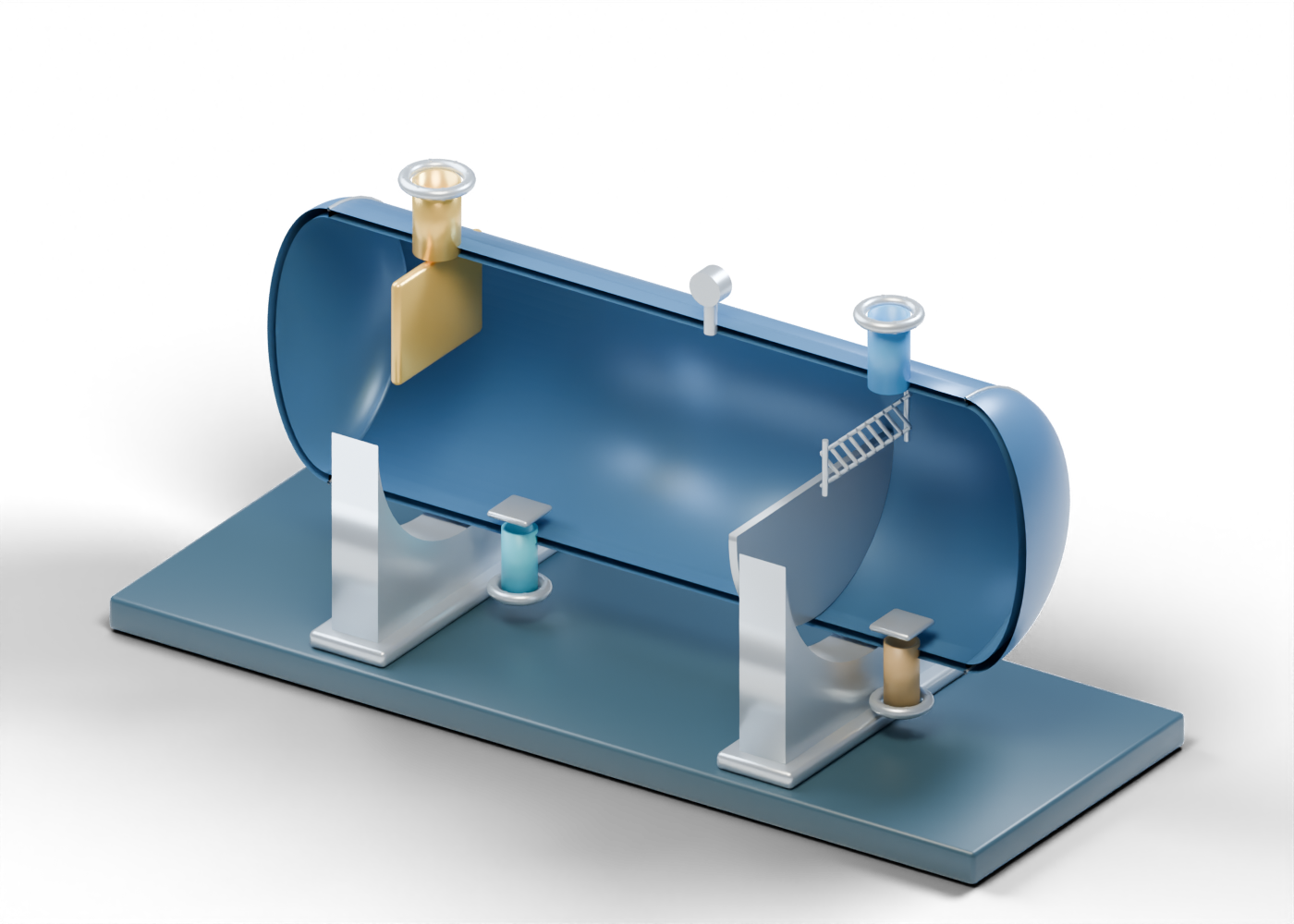
Base frame
Illustrative support frame; foundations and structural design vary.
Vessel shell
Hollow cylindrical enclosure with five geometric connection openings. Wall thickness, proportions and junctions are illustrative; no reinforcement, weld or pressure qualification.
Dished head -1
Generic double-surface dished closure. Shape and thickness are illustrative, with no code qualification.
Circumferential seam -1
Illustrates a shell-to-head seam location, without weld detail.
Dished head 1
Generic double-surface dished closure. Shape and thickness are illustrative, with no code qualification.
Circumferential seam 1
Illustrates a shell-to-head seam location, without weld detail.
Saddle support -1.6
Curved saddle supports the cylindrical wall; structural design is not specified.
Saddle foot -1.6
Illustrative attachment to a support frame.
Saddle support 1.6
Curved saddle supports the cylindrical wall; structural design is not specified.
Saddle foot 1.6
Illustrative attachment to a support frame.
Feed nozzle
Hollow generic connection with illustrative wall thickness. Welds, facing and pressure ratings are not specified.
Feed nozzle flange
Illustrative flange ring, with no rated facing or bolt specification.
Feed nozzle fastener 1
Generic fastener position. Quantity and size do not specify a rated connection.
Feed nozzle fastener 2
Generic fastener position. Quantity and size do not specify a rated connection.
Feed nozzle fastener 3
Generic fastener position. Quantity and size do not specify a rated connection.
Feed nozzle fastener 4
Generic fastener position. Quantity and size do not specify a rated connection.
Feed nozzle fastener 5
Generic fastener position. Quantity and size do not specify a rated connection.
Feed nozzle fastener 6
Generic fastener position. Quantity and size do not specify a rated connection.
Feed nozzle fastener 7
Generic fastener position. Quantity and size do not specify a rated connection.
Feed nozzle fastener 8
Generic fastener position. Quantity and size do not specify a rated connection.
Inlet diverter
Redirects incoming flow toward the separation zone; this plate is a conceptual arrangement.
Water region
Illustrative phase volume following the vessel cross-section. Interfaces are static teaching positions, not measured levels or a flow simulation.
Oil region
Illustrative phase volume following the vessel cross-section. Interfaces are static teaching positions, not measured levels or a flow simulation.
Gas space
Illustrative phase volume following the vessel cross-section. Interfaces are static teaching positions, not measured levels or a flow simulation.
Liquid weir
Conceptual overflow weir separates the upstream settling zone from an oil collection compartment. Real arrangements vary.
Oil collection compartment
Illustrates oil collected beyond the weir; no operating level is specified.
Demister frame -0.48
Supports a conceptual mist-removal pack.
Demister frame 0.48
Supports a conceptual mist-removal pack.
Mist vane 0 segment 0
Zigzag teaching representation of a vane pack that helps collect entrained droplets. Performance and production geometry are not reproduced.
Mist vane 0 segment 1
Zigzag teaching representation of a vane pack that helps collect entrained droplets. Performance and production geometry are not reproduced.
Mist vane 0 segment 2
Zigzag teaching representation of a vane pack that helps collect entrained droplets. Performance and production geometry are not reproduced.
Mist vane 1 segment 0
Zigzag teaching representation of a vane pack that helps collect entrained droplets. Performance and production geometry are not reproduced.
Mist vane 1 segment 1
Zigzag teaching representation of a vane pack that helps collect entrained droplets. Performance and production geometry are not reproduced.
Mist vane 1 segment 2
Zigzag teaching representation of a vane pack that helps collect entrained droplets. Performance and production geometry are not reproduced.
Mist vane 2 segment 0
Zigzag teaching representation of a vane pack that helps collect entrained droplets. Performance and production geometry are not reproduced.
Mist vane 2 segment 1
Zigzag teaching representation of a vane pack that helps collect entrained droplets. Performance and production geometry are not reproduced.
Mist vane 2 segment 2
Zigzag teaching representation of a vane pack that helps collect entrained droplets. Performance and production geometry are not reproduced.
Mist vane 3 segment 0
Zigzag teaching representation of a vane pack that helps collect entrained droplets. Performance and production geometry are not reproduced.
Mist vane 3 segment 1
Zigzag teaching representation of a vane pack that helps collect entrained droplets. Performance and production geometry are not reproduced.
Mist vane 3 segment 2
Zigzag teaching representation of a vane pack that helps collect entrained droplets. Performance and production geometry are not reproduced.
Mist vane 4 segment 0
Zigzag teaching representation of a vane pack that helps collect entrained droplets. Performance and production geometry are not reproduced.
Mist vane 4 segment 1
Zigzag teaching representation of a vane pack that helps collect entrained droplets. Performance and production geometry are not reproduced.
Mist vane 4 segment 2
Zigzag teaching representation of a vane pack that helps collect entrained droplets. Performance and production geometry are not reproduced.
Mist vane 5 segment 0
Zigzag teaching representation of a vane pack that helps collect entrained droplets. Performance and production geometry are not reproduced.
Mist vane 5 segment 1
Zigzag teaching representation of a vane pack that helps collect entrained droplets. Performance and production geometry are not reproduced.
Mist vane 5 segment 2
Zigzag teaching representation of a vane pack that helps collect entrained droplets. Performance and production geometry are not reproduced.
Mist vane 6 segment 0
Zigzag teaching representation of a vane pack that helps collect entrained droplets. Performance and production geometry are not reproduced.
Mist vane 6 segment 1
Zigzag teaching representation of a vane pack that helps collect entrained droplets. Performance and production geometry are not reproduced.
Mist vane 6 segment 2
Zigzag teaching representation of a vane pack that helps collect entrained droplets. Performance and production geometry are not reproduced.
Mist vane 7 segment 0
Zigzag teaching representation of a vane pack that helps collect entrained droplets. Performance and production geometry are not reproduced.
Mist vane 7 segment 1
Zigzag teaching representation of a vane pack that helps collect entrained droplets. Performance and production geometry are not reproduced.
Mist vane 7 segment 2
Zigzag teaching representation of a vane pack that helps collect entrained droplets. Performance and production geometry are not reproduced.
Mist vane 8 segment 0
Zigzag teaching representation of a vane pack that helps collect entrained droplets. Performance and production geometry are not reproduced.
Mist vane 8 segment 1
Zigzag teaching representation of a vane pack that helps collect entrained droplets. Performance and production geometry are not reproduced.
Mist vane 8 segment 2
Zigzag teaching representation of a vane pack that helps collect entrained droplets. Performance and production geometry are not reproduced.
Gas outlet
Hollow generic connection with illustrative wall thickness. Welds, facing and pressure ratings are not specified.
Gas outlet flange
Illustrative flange ring, with no rated facing or bolt specification.
Gas outlet fastener 1
Generic fastener position. Quantity and size do not specify a rated connection.
Gas outlet fastener 2
Generic fastener position. Quantity and size do not specify a rated connection.
Gas outlet fastener 3
Generic fastener position. Quantity and size do not specify a rated connection.
Gas outlet fastener 4
Generic fastener position. Quantity and size do not specify a rated connection.
Gas outlet fastener 5
Generic fastener position. Quantity and size do not specify a rated connection.
Gas outlet fastener 6
Generic fastener position. Quantity and size do not specify a rated connection.
Gas outlet fastener 7
Generic fastener position. Quantity and size do not specify a rated connection.
Gas outlet fastener 8
Generic fastener position. Quantity and size do not specify a rated connection.
Oil outlet
Hollow generic connection with illustrative wall thickness. Welds, facing and pressure ratings are not specified.
Oil outlet flange
Illustrative flange ring, with no rated facing or bolt specification.
Oil outlet fastener 1
Generic fastener position. Quantity and size do not specify a rated connection.
Oil outlet fastener 2
Generic fastener position. Quantity and size do not specify a rated connection.
Oil outlet fastener 3
Generic fastener position. Quantity and size do not specify a rated connection.
Oil outlet fastener 4
Generic fastener position. Quantity and size do not specify a rated connection.
Oil outlet fastener 5
Generic fastener position. Quantity and size do not specify a rated connection.
Oil outlet fastener 6
Generic fastener position. Quantity and size do not specify a rated connection.
Oil outlet fastener 7
Generic fastener position. Quantity and size do not specify a rated connection.
Oil outlet fastener 8
Generic fastener position. Quantity and size do not specify a rated connection.
Water outlet
Hollow generic connection with illustrative wall thickness. Welds, facing and pressure ratings are not specified.
Water outlet flange
Illustrative flange ring, with no rated facing or bolt specification.
Water outlet fastener 1
Generic fastener position. Quantity and size do not specify a rated connection.
Water outlet fastener 2
Generic fastener position. Quantity and size do not specify a rated connection.
Water outlet fastener 3
Generic fastener position. Quantity and size do not specify a rated connection.
Water outlet fastener 4
Generic fastener position. Quantity and size do not specify a rated connection.
Water outlet fastener 5
Generic fastener position. Quantity and size do not specify a rated connection.
Water outlet fastener 6
Generic fastener position. Quantity and size do not specify a rated connection.
Water outlet fastener 7
Generic fastener position. Quantity and size do not specify a rated connection.
Water outlet fastener 8
Generic fastener position. Quantity and size do not specify a rated connection.
Oil outlet vortex breaker
A schematic plate over a liquid draw-off; real vortex-breaker design and clearance depend on duty.
Water outlet vortex breaker
A schematic plate over a liquid draw-off; real vortex-breaker design and clearance depend on duty.
Pressure instrument connection
Hollow conceptual instrument tapping through the vessel wall; no measurement, calibration or control loop is provided.
Pressure indicator
Illustrative gauge location with no numerical reading.