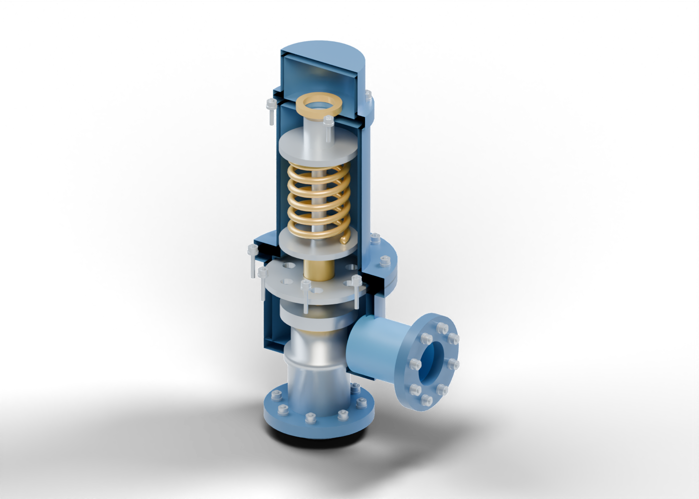
Inlet flange
Hollow inlet flange marker with eight actual fastener bores. No pressure class or attached system.
Hollow stepped nozzle
Original hollow nozzle with a geometric bore and upper annular seat plane. Invented proportions, no rated orifice, flow capacity, materials or seat finish.
Body lower shoulder
Annular body shoulder around the nozzle region. No qualified nozzle attachment or pressure boundary.
Hollow body wall
Hollow chamber wall with an actual lateral outlet bore. No casting, pressure or fluid calculation.
Hollow outlet neck
Open side connection from the body region to a separate flange. No downstream destination, piping or backpressure qualification.
Outlet flange
Hollow lateral flange with eight real stud bores. No rated facing or mating pipe.
Closure disc
Separate solid disc above the annular nozzle seat in a static adjacent pose. No leakage, pressure response or qualified sealing.
Disc holder
Separate bored carrier above the disc. Invented support relationship, without balance, lift or rated retention.
Spindle contact marker
Separate spherical contact marker between the spindle region and holder. No contact force, articulation or qualified attachment.
Smooth spindle
Solid central spindle marker connecting the disc-side and spring-seat regions. Static pose; no force transfer or travel qualification.
Perforated guide support
Separate annular guide support with six actual openings around the spindle region. No rated internal guide design.
Spindle guide bushing
Hollow guide marker around the spindle. Invented radial gap; no running fit, wear or alignment qualification.
Body bonnet flange
Annular body flange with actual matching bonnet-joint holes. No rated body-to-bonnet pressure joint.
Bonnet gasket marker
Separate gasket marker with matching geometric fastener holes. Material and compression are unspecified.
Bonnet base flange
Separate annular bonnet flange. No facing, bolt load or pressure rating.
Hollow spring bonnet
Hollow enclosure around a separate spring and seats. No pressure, vent, bellows or backpressure qualification.
Lower spring seat
Separate annular lower seat above the spindle guide region. Spring loading is not calculated.
Upper spring seat
Separate annular upper seat below the setting marker. No preload or set-pressure result.
Closed coil spring
Original closed six-turn coil between separate seat markers. No spring rate, preload, force, fatigue, temperature or set-pressure calibration.
Hollow setting marker
Hollow axial setting marker above the spring seat. Unthreaded static geometry; no adjustment, calibration or operating instruction.
Bonnet upper bridge
Bored upper bridge surrounding the setting marker. Four cap-joint bores are actual geometry.
Setting lock marker
Bored locking-location marker. No thread form, torque or qualified locking.
Cap flange
Separate annular cap flange sharing four actual joint holes with the upper bridge.
Hollow protective cap
Hollow presentation enclosure above the setting region. No tamper seal, vent or pressure qualification.
Cap lid
Solid upper closure marker; no rated closure or pressure boundary.
Inlet joint stud 1
Separate smooth stud through a geometric hole. No threads, preload, torque or rated joint.
Inlet joint washer 1
Separate bored washer marker; no fastener-load qualification.
Inlet joint nut 1
Separate circular bored nut marker. No threads, wrench dimensions or qualified retention.
Inlet joint stud 2
Separate smooth stud through a geometric hole. No threads, preload, torque or rated joint.
Inlet joint washer 2
Separate bored washer marker; no fastener-load qualification.
Inlet joint nut 2
Separate circular bored nut marker. No threads, wrench dimensions or qualified retention.
Inlet joint stud 3
Separate smooth stud through a geometric hole. No threads, preload, torque or rated joint.
Inlet joint washer 3
Separate bored washer marker; no fastener-load qualification.
Inlet joint nut 3
Separate circular bored nut marker. No threads, wrench dimensions or qualified retention.
Inlet joint stud 4
Separate smooth stud through a geometric hole. No threads, preload, torque or rated joint.
Inlet joint washer 4
Separate bored washer marker; no fastener-load qualification.
Inlet joint nut 4
Separate circular bored nut marker. No threads, wrench dimensions or qualified retention.
Inlet joint stud 5
Separate smooth stud through a geometric hole. No threads, preload, torque or rated joint.
Inlet joint washer 5
Separate bored washer marker; no fastener-load qualification.
Inlet joint nut 5
Separate circular bored nut marker. No threads, wrench dimensions or qualified retention.
Inlet joint stud 6
Separate smooth stud through a geometric hole. No threads, preload, torque or rated joint.
Inlet joint washer 6
Separate bored washer marker; no fastener-load qualification.
Inlet joint nut 6
Separate circular bored nut marker. No threads, wrench dimensions or qualified retention.
Inlet joint stud 7
Separate smooth stud through a geometric hole. No threads, preload, torque or rated joint.
Inlet joint washer 7
Separate bored washer marker; no fastener-load qualification.
Inlet joint nut 7
Separate circular bored nut marker. No threads, wrench dimensions or qualified retention.
Inlet joint stud 8
Separate smooth stud through a geometric hole. No threads, preload, torque or rated joint.
Inlet joint washer 8
Separate bored washer marker; no fastener-load qualification.
Inlet joint nut 8
Separate circular bored nut marker. No threads, wrench dimensions or qualified retention.
Outlet joint stud 1
Separate smooth stud through a geometric hole. No threads, preload, torque or rated joint.
Outlet joint washer 1
Separate bored washer marker; no fastener-load qualification.
Outlet joint nut 1
Separate circular bored nut marker. No threads, wrench dimensions or qualified retention.
Outlet joint stud 2
Separate smooth stud through a geometric hole. No threads, preload, torque or rated joint.
Outlet joint washer 2
Separate bored washer marker; no fastener-load qualification.
Outlet joint nut 2
Separate circular bored nut marker. No threads, wrench dimensions or qualified retention.
Outlet joint stud 3
Separate smooth stud through a geometric hole. No threads, preload, torque or rated joint.
Outlet joint washer 3
Separate bored washer marker; no fastener-load qualification.
Outlet joint nut 3
Separate circular bored nut marker. No threads, wrench dimensions or qualified retention.
Outlet joint stud 4
Separate smooth stud through a geometric hole. No threads, preload, torque or rated joint.
Outlet joint washer 4
Separate bored washer marker; no fastener-load qualification.
Outlet joint nut 4
Separate circular bored nut marker. No threads, wrench dimensions or qualified retention.
Outlet joint stud 5
Separate smooth stud through a geometric hole. No threads, preload, torque or rated joint.
Outlet joint washer 5
Separate bored washer marker; no fastener-load qualification.
Outlet joint nut 5
Separate circular bored nut marker. No threads, wrench dimensions or qualified retention.
Outlet joint stud 6
Separate smooth stud through a geometric hole. No threads, preload, torque or rated joint.
Outlet joint washer 6
Separate bored washer marker; no fastener-load qualification.
Outlet joint nut 6
Separate circular bored nut marker. No threads, wrench dimensions or qualified retention.
Outlet joint stud 7
Separate smooth stud through a geometric hole. No threads, preload, torque or rated joint.
Outlet joint washer 7
Separate bored washer marker; no fastener-load qualification.
Outlet joint nut 7
Separate circular bored nut marker. No threads, wrench dimensions or qualified retention.
Outlet joint stud 8
Separate smooth stud through a geometric hole. No threads, preload, torque or rated joint.
Outlet joint washer 8
Separate bored washer marker; no fastener-load qualification.
Outlet joint nut 8
Separate circular bored nut marker. No threads, wrench dimensions or qualified retention.
Bonnet joint stud 1
Separate smooth stud through a geometric hole. No threads, preload, torque or rated joint.
Bonnet joint washer 1
Separate bored washer marker; no fastener-load qualification.
Bonnet joint nut 1
Separate circular bored nut marker. No threads, wrench dimensions or qualified retention.
Bonnet joint stud 2
Separate smooth stud through a geometric hole. No threads, preload, torque or rated joint.
Bonnet joint washer 2
Separate bored washer marker; no fastener-load qualification.
Bonnet joint nut 2
Separate circular bored nut marker. No threads, wrench dimensions or qualified retention.
Bonnet joint stud 3
Separate smooth stud through a geometric hole. No threads, preload, torque or rated joint.
Bonnet joint washer 3
Separate bored washer marker; no fastener-load qualification.
Bonnet joint nut 3
Separate circular bored nut marker. No threads, wrench dimensions or qualified retention.
Bonnet joint stud 4
Separate smooth stud through a geometric hole. No threads, preload, torque or rated joint.
Bonnet joint washer 4
Separate bored washer marker; no fastener-load qualification.
Bonnet joint nut 4
Separate circular bored nut marker. No threads, wrench dimensions or qualified retention.
Bonnet joint stud 5
Separate smooth stud through a geometric hole. No threads, preload, torque or rated joint.
Bonnet joint washer 5
Separate bored washer marker; no fastener-load qualification.
Bonnet joint nut 5
Separate circular bored nut marker. No threads, wrench dimensions or qualified retention.
Bonnet joint stud 6
Separate smooth stud through a geometric hole. No threads, preload, torque or rated joint.
Bonnet joint washer 6
Separate bored washer marker; no fastener-load qualification.
Bonnet joint nut 6
Separate circular bored nut marker. No threads, wrench dimensions or qualified retention.
Bonnet joint stud 7
Separate smooth stud through a geometric hole. No threads, preload, torque or rated joint.
Bonnet joint washer 7
Separate bored washer marker; no fastener-load qualification.
Bonnet joint nut 7
Separate circular bored nut marker. No threads, wrench dimensions or qualified retention.
Bonnet joint stud 8
Separate smooth stud through a geometric hole. No threads, preload, torque or rated joint.
Bonnet joint washer 8
Separate bored washer marker; no fastener-load qualification.
Bonnet joint nut 8
Separate circular bored nut marker. No threads, wrench dimensions or qualified retention.
Cap joint stud 1
Separate smooth stud through a geometric hole. No threads, preload, torque or rated joint.
Cap joint washer 1
Separate bored washer marker; no fastener-load qualification.
Cap joint nut 1
Separate circular bored nut marker. No threads, wrench dimensions or qualified retention.
Cap joint stud 2
Separate smooth stud through a geometric hole. No threads, preload, torque or rated joint.
Cap joint washer 2
Separate bored washer marker; no fastener-load qualification.
Cap joint nut 2
Separate circular bored nut marker. No threads, wrench dimensions or qualified retention.
Cap joint stud 3
Separate smooth stud through a geometric hole. No threads, preload, torque or rated joint.
Cap joint washer 3
Separate bored washer marker; no fastener-load qualification.
Cap joint nut 3
Separate circular bored nut marker. No threads, wrench dimensions or qualified retention.
Cap joint stud 4
Separate smooth stud through a geometric hole. No threads, preload, torque or rated joint.
Cap joint washer 4
Separate bored washer marker; no fastener-load qualification.
Cap joint nut 4
Separate circular bored nut marker. No threads, wrench dimensions or qualified retention.