Base frame
Illustrative support frame; foundations and structural design vary.
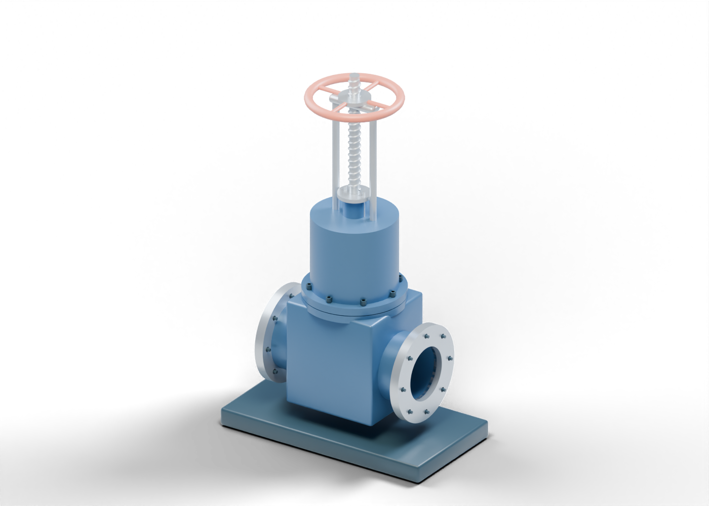
Valve body
Original generic body with an open axial passage and upper gate pocket. No pressure rating, casting detail or design dimensions.
Flow neck -1
Hollow passage connects the body to an end flange. Wall thickness is illustrative.
End flange -1
Annular flange with eight geometric bolt holes; no rated facing, gasket or bolt specification.
Connection stud -1 / 1
Illustrative fastener position, without a mating pipe flange or torque specification.
Connection stud -1 / 2
Illustrative fastener position, without a mating pipe flange or torque specification.
Connection stud -1 / 3
Illustrative fastener position, without a mating pipe flange or torque specification.
Connection stud -1 / 4
Illustrative fastener position, without a mating pipe flange or torque specification.
Connection stud -1 / 5
Illustrative fastener position, without a mating pipe flange or torque specification.
Connection stud -1 / 6
Illustrative fastener position, without a mating pipe flange or torque specification.
Connection stud -1 / 7
Illustrative fastener position, without a mating pipe flange or torque specification.
Connection stud -1 / 8
Illustrative fastener position, without a mating pipe flange or torque specification.
Seat -1
Angled annular seat adjoining the tapered wedge. Contact geometry is conceptual; sealing performance and tolerances are not verified.
Flow neck 1
Hollow passage connects the body to an end flange. Wall thickness is illustrative.
End flange 1
Annular flange with eight geometric bolt holes; no rated facing, gasket or bolt specification.
Connection stud 1 / 1
Illustrative fastener position, without a mating pipe flange or torque specification.
Connection stud 1 / 2
Illustrative fastener position, without a mating pipe flange or torque specification.
Connection stud 1 / 3
Illustrative fastener position, without a mating pipe flange or torque specification.
Connection stud 1 / 4
Illustrative fastener position, without a mating pipe flange or torque specification.
Connection stud 1 / 5
Illustrative fastener position, without a mating pipe flange or torque specification.
Connection stud 1 / 6
Illustrative fastener position, without a mating pipe flange or torque specification.
Connection stud 1 / 7
Illustrative fastener position, without a mating pipe flange or torque specification.
Connection stud 1 / 8
Illustrative fastener position, without a mating pipe flange or torque specification.
Seat 1
Angled annular seat adjoining the tapered wedge. Contact geometry is conceptual; sealing performance and tolerances are not verified.
Gate
Original tapered wedge crosses the bore in the depicted closed pose. Travel is a geometric demonstration, without leakage, load or operating-force simulation.
Stem-to-gate connection
Schematic attachment between stem and wedge. Retention detail and loads are not designed.
Stem
Rising stem translates with the gate. The smooth lower region passes through packing; operating loads and exact thread engagement are omitted.
Stem thread crest
Continuous helical teaching crest. Pitch, profile and fit are illustrative; the matching internal nut thread is omitted.
Body bonnet flange
Generic hollow bonnet/packing boundary. This is a schematic assembly without joint qualification or a maintenance procedure.
Bonnet flange
Generic hollow bonnet/packing boundary. This is a schematic assembly without joint qualification or a maintenance procedure.
Bonnet gasket
Generic hollow bonnet/packing boundary. This is a schematic assembly without joint qualification or a maintenance procedure.
Bonnet chamber
Generic hollow bonnet/packing boundary. This is a schematic assembly without joint qualification or a maintenance procedure.
Bonnet shoulder
Generic hollow bonnet/packing boundary. This is a schematic assembly without joint qualification or a maintenance procedure.
Packing chamber
Generic hollow bonnet/packing boundary. This is a schematic assembly without joint qualification or a maintenance procedure.
Bonnet stud 1
Illustrative bonnet fastener; no bolt stress or torque specification.
Bonnet nut 1
Generic hexagonal nut marker.
Bonnet stud 2
Illustrative bonnet fastener; no bolt stress or torque specification.
Bonnet nut 2
Generic hexagonal nut marker.
Bonnet stud 3
Illustrative bonnet fastener; no bolt stress or torque specification.
Bonnet nut 3
Generic hexagonal nut marker.
Bonnet stud 4
Illustrative bonnet fastener; no bolt stress or torque specification.
Bonnet nut 4
Generic hexagonal nut marker.
Bonnet stud 5
Illustrative bonnet fastener; no bolt stress or torque specification.
Bonnet nut 5
Generic hexagonal nut marker.
Bonnet stud 6
Illustrative bonnet fastener; no bolt stress or torque specification.
Bonnet nut 6
Generic hexagonal nut marker.
Bonnet stud 7
Illustrative bonnet fastener; no bolt stress or torque specification.
Bonnet nut 7
Generic hexagonal nut marker.
Bonnet stud 8
Illustrative bonnet fastener; no bolt stress or torque specification.
Bonnet nut 8
Generic hexagonal nut marker.
Packing ring 1
Separate conceptual packing ring around the smooth stem. Material, compression and fugitive-emission performance are not specified.
Packing ring 2
Separate conceptual packing ring around the smooth stem. Material, compression and fugitive-emission performance are not specified.
Packing ring 3
Separate conceptual packing ring around the smooth stem. Material, compression and fugitive-emission performance are not specified.
Packing ring 4
Separate conceptual packing ring around the smooth stem. Material, compression and fugitive-emission performance are not specified.
Gland follower
Conceptual stem operating or packing component; no adjustment procedure or rated specification.
Gland flange
Conceptual stem operating or packing component; no adjustment procedure or rated specification.
Stem nut
Conceptual stem operating or packing component; no adjustment procedure or rated specification.
Handwheel hub
Conceptual stem operating or packing component; no adjustment procedure or rated specification.
Yoke leg -0.28
Supports the stationary operating nut above the packing.
Gland stud -0.28
Illustrative gland fastener position. No packing adjustment or torque instruction.
Yoke leg 0.28
Supports the stationary operating nut above the packing.
Gland stud 0.28
Illustrative gland fastener position. No packing adjustment or torque instruction.
Yoke bridge
Connects the yoke legs at the operating nut.
Handwheel
Manual wheel concept. The travel slider does not simulate wheel turns or operating force.
Wheel spoke 1
Connects the handwheel rim to its hub.
Wheel spoke 2
Connects the handwheel rim to its hub.
Wheel spoke 3
Connects the handwheel rim to its hub.
Wheel spoke 4
Connects the handwheel rim to its hub.