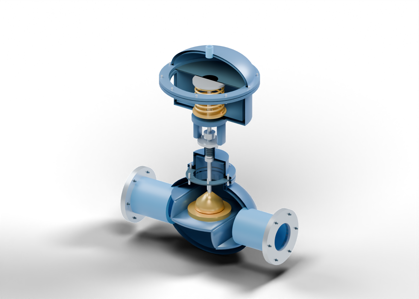
Globe body
Double-surface rounded chamber around a stepped partition and vertical seat port. Original invented proportions; no rated design, verified fit or manufacturing specification.
Inlet chamber web
Stepped internal partition marker. It distinguishes passage sides; wall joins, casting feasibility and sealing are unqualified. Original invented proportions; no rated design, verified fit or manufacturing specification.
Outlet chamber web
Stepped internal partition marker. It distinguishes passage sides; wall joins, casting feasibility and sealing are unqualified. Original invented proportions; no rated design, verified fit or manufacturing specification.
Seat support web
Stepped internal partition marker. It distinguishes passage sides; wall joins, casting feasibility and sealing are unqualified. Original invented proportions; no rated design, verified fit or manufacturing specification.
Inlet web riser
Vertical transition between partition levels. This invented web does not establish a pressure-qualified body or calculated flow distribution.
Outlet web riser
Vertical transition between partition levels. This invented web does not establish a pressure-qualified body or calculated flow distribution.
Control seat
Separate annular seat around a vertical port, supported by the central web. Retention, contact stress and leakage are unspecified.
Inlet process neck
Hollow process connection into the rounded valve chamber. Original invented proportions; no rated design, verified fit or manufacturing specification.
Inlet process flange
Bored six-position connection flange. No adjoining piping, gasket, facing or joint rating.
Inlet flange stud 1
Generic fastener marker without threads or torque.
Inlet flange stud 2
Generic fastener marker without threads or torque.
Inlet flange stud 3
Generic fastener marker without threads or torque.
Inlet flange stud 4
Generic fastener marker without threads or torque.
Inlet flange stud 5
Generic fastener marker without threads or torque.
Inlet flange stud 6
Generic fastener marker without threads or torque.
Outlet process neck
Hollow process connection into the rounded valve chamber. Original invented proportions; no rated design, verified fit or manufacturing specification.
Outlet process flange
Bored six-position connection flange. No adjoining piping, gasket, facing or joint rating.
Outlet flange stud 1
Generic fastener marker without threads or torque.
Outlet flange stud 2
Generic fastener marker without threads or torque.
Outlet flange stud 3
Generic fastener marker without threads or torque.
Outlet flange stud 4
Generic fastener marker without threads or torque.
Outlet flange stud 5
Generic fastener marker without threads or torque.
Outlet flange stud 6
Generic fastener marker without threads or torque.
Bonnet neck
Separate hollow bonnet, packing, support or actuator component. Role is a teaching concept; geometry and materials are unqualified. Original invented proportions; no rated design, verified fit or manufacturing specification.
Body bonnet flange
Separate hollow bonnet, packing, support or actuator component. Role is a teaching concept; geometry and materials are unqualified. Original invented proportions; no rated design, verified fit or manufacturing specification.
Bonnet gasket
Separate hollow bonnet, packing, support or actuator component. Role is a teaching concept; geometry and materials are unqualified. Original invented proportions; no rated design, verified fit or manufacturing specification.
Bonnet flange
Separate hollow bonnet, packing, support or actuator component. Role is a teaching concept; geometry and materials are unqualified. Original invented proportions; no rated design, verified fit or manufacturing specification.
Bonnet chamber
Separate hollow bonnet, packing, support or actuator component. Role is a teaching concept; geometry and materials are unqualified. Original invented proportions; no rated design, verified fit or manufacturing specification.
Bonnet shoulder
Separate hollow bonnet, packing, support or actuator component. Role is a teaching concept; geometry and materials are unqualified. Original invented proportions; no rated design, verified fit or manufacturing specification.
Bonnet stem guide
Separate hollow bonnet, packing, support or actuator component. Role is a teaching concept; geometry and materials are unqualified. Original invented proportions; no rated design, verified fit or manufacturing specification.
Packing housing
Separate hollow bonnet, packing, support or actuator component. Role is a teaching concept; geometry and materials are unqualified. Original invented proportions; no rated design, verified fit or manufacturing specification.
Packing lower support
Separate hollow bonnet, packing, support or actuator component. Role is a teaching concept; geometry and materials are unqualified. Original invented proportions; no rated design, verified fit or manufacturing specification.
Packing follower
Separate hollow bonnet, packing, support or actuator component. Role is a teaching concept; geometry and materials are unqualified. Original invented proportions; no rated design, verified fit or manufacturing specification.
Gland flange
Separate hollow bonnet, packing, support or actuator component. Role is a teaching concept; geometry and materials are unqualified. Original invented proportions; no rated design, verified fit or manufacturing specification.
Yoke bridge
Separate hollow bonnet, packing, support or actuator component. Role is a teaching concept; geometry and materials are unqualified. Original invented proportions; no rated design, verified fit or manufacturing specification.
Actuator stem guide
Separate hollow bonnet, packing, support or actuator component. Role is a teaching concept; geometry and materials are unqualified. Original invented proportions; no rated design, verified fit or manufacturing specification.
Lower actuator base
Separate hollow bonnet, packing, support or actuator component. Role is a teaching concept; geometry and materials are unqualified. Original invented proportions; no rated design, verified fit or manufacturing specification.
Lower actuator shell
Separate hollow bonnet, packing, support or actuator component. Role is a teaching concept; geometry and materials are unqualified. Original invented proportions; no rated design, verified fit or manufacturing specification.
Lower diaphragm flange
Separate hollow bonnet, packing, support or actuator component. Role is a teaching concept; geometry and materials are unqualified. Original invented proportions; no rated design, verified fit or manufacturing specification.
Upper diaphragm flange
Separate hollow bonnet, packing, support or actuator component. Role is a teaching concept; geometry and materials are unqualified. Original invented proportions; no rated design, verified fit or manufacturing specification.
Lower spring seat
Separate hollow bonnet, packing, support or actuator component. Role is a teaching concept; geometry and materials are unqualified. Original invented proportions; no rated design, verified fit or manufacturing specification.
Control packing ring 1
Separate annular packing marker around the smooth moving stem. Compression, material, emissions and adjustment are unspecified.
Control packing ring 2
Separate annular packing marker around the smooth moving stem. Compression, material, emissions and adjustment are unspecified.
Control packing ring 3
Separate annular packing marker around the smooth moving stem. Compression, material, emissions and adjustment are unspecified.
Control packing ring 4
Separate annular packing marker around the smooth moving stem. Compression, material, emissions and adjustment are unspecified.
Actuator yoke leg -1
Stationary support between the bonnet and actuator. Structural loads and mounting are unqualified.
Gland stud -1
Generic gland fastening marker, with no packing-adjustment instruction.
Actuator yoke leg 1
Stationary support between the bonnet and actuator. Structural loads and mounting are unqualified.
Gland stud 1
Generic gland fastening marker, with no packing-adjustment instruction.
Bonnet joint stud 1
Generic bonnet fastener position; threads and joint loads omitted.
Bonnet joint stud 2
Generic bonnet fastener position; threads and joint loads omitted.
Bonnet joint stud 3
Generic bonnet fastener position; threads and joint loads omitted.
Bonnet joint stud 4
Generic bonnet fastener position; threads and joint loads omitted.
Bonnet joint stud 5
Generic bonnet fastener position; threads and joint loads omitted.
Bonnet joint stud 6
Generic bonnet fastener position; threads and joint loads omitted.
Actuator diaphragm
Flexible boundary marker with a clamped outer rim and an arbitrary centre-displacement shape. It is not a rolling-diaphragm design, pressure calculation or measured deformation.
Actuator spring
Continuous six-turn spring marker. Its upper end follows the plate geometrically; stiffness, preload, force, contact and return/failure behaviour are not calculated.
Upper actuator dome
Hollow original dome above the diaphragm, with an open air tapping. Wall thickness, joint sealing and pressure containment are unqualified.
Actuator air connection
Hollow tapping into the upper chamber. Air supply, regulator, exhaust, tubing, positioner and controller are outside the model.
Diaphragm joint bolt 1
Generic clamping-joint fastener marker. Threads, torque and sealing are omitted.
Diaphragm joint bolt 2
Generic clamping-joint fastener marker. Threads, torque and sealing are omitted.
Diaphragm joint bolt 3
Generic clamping-joint fastener marker. Threads, torque and sealing are omitted.
Diaphragm joint bolt 4
Generic clamping-joint fastener marker. Threads, torque and sealing are omitted.
Diaphragm joint bolt 5
Generic clamping-joint fastener marker. Threads, torque and sealing are omitted.
Diaphragm joint bolt 6
Generic clamping-joint fastener marker. Threads, torque and sealing are omitted.
Diaphragm joint bolt 7
Generic clamping-joint fastener marker. Threads, torque and sealing are omitted.
Diaphragm joint bolt 8
Generic clamping-joint fastener marker. Threads, torque and sealing are omitted.
Diaphragm joint bolt 9
Generic clamping-joint fastener marker. Threads, torque and sealing are omitted.
Diaphragm joint bolt 10
Generic clamping-joint fastener marker. Threads, torque and sealing are omitted.
Control plug
Original solid contoured closure above the annular seat. Shape provides no flow characteristic, Cv, leakage class or cavitation performance.
Valve stem
Smooth valve stem connecting the plug through the packing toward the actuator. Loads and fit are unqualified.
Stem connector
Generic separate stem-connection sleeve. Mating threads, adjustment and locking details are omitted.
Actuator stem
Actuator rod links the stem connector to the diaphragm plate. Travel is an arbitrary coordinated geometry illustration.
Diaphragm plate
Rigid central plate under the diaphragm. Plate, rods and plug translate together while the diaphragm rim remains fixed.