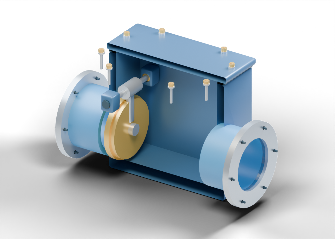
Check body
Hollow chamber with two axial bores and an open top access joint. Invented teaching proportions; no pressure rating, verified fit or material specification.
Check seat
Separate annular seat beside the hinged disc. Contact stress, lapping, retention and leakage are unspecified. Invented teaching proportions; no pressure rating, verified fit or material specification.
Inlet neck
Open connection toward the valve chamber. Invented teaching proportions; no pressure rating, verified fit or material specification.
Inlet flange
Annular connection flange with six bored fastener positions; adjoining pipe, gasket and joint qualification are absent. Invented teaching proportions; no pressure rating, verified fit or material specification.
Inlet stud 1
Generic separate fastening position, without threads, preload or torque.
Inlet stud 2
Generic separate fastening position, without threads, preload or torque.
Inlet stud 3
Generic separate fastening position, without threads, preload or torque.
Inlet stud 4
Generic separate fastening position, without threads, preload or torque.
Inlet stud 5
Generic separate fastening position, without threads, preload or torque.
Inlet stud 6
Generic separate fastening position, without threads, preload or torque.
Outlet neck
Open connection toward the valve chamber. Invented teaching proportions; no pressure rating, verified fit or material specification.
Outlet flange
Annular connection flange with six bored fastener positions; adjoining pipe, gasket and joint qualification are absent. Invented teaching proportions; no pressure rating, verified fit or material specification.
Outlet stud 1
Generic separate fastening position, without threads, preload or torque.
Outlet stud 2
Generic separate fastening position, without threads, preload or torque.
Outlet stud 3
Generic separate fastening position, without threads, preload or torque.
Outlet stud 4
Generic separate fastening position, without threads, preload or torque.
Outlet stud 5
Generic separate fastening position, without threads, preload or torque.
Outlet stud 6
Generic separate fastening position, without threads, preload or torque.
Hinge support -1
Body-mounted hinge support concept. Attachment strength and wear are unspecified.
Hinge bushing -1
Separate bored bushing around the stationary pin. Bearing fit and lubrication are unspecified.
Hinge support 1
Body-mounted hinge support concept. Attachment strength and wear are unspecified.
Hinge bushing 1
Separate bored bushing around the stationary pin. Bearing fit and lubrication are unspecified.
Hinge pin
Stationary pivot axis supported on both sides of the chamber. It does not represent a qualified retention design.
Pin end marker -1
Separate generic pin-end retention marker; actual locking hardware is omitted.
Pin end marker 1
Separate generic pin-end retention marker; actual locking hardware is omitted.
Check disc
Solid circular closure in a neutral seat-adjacent pose. Disc rotation is an independent geometric illustration, not pressure-responsive motion.
Disc hinge arm
Connects the disc back to the bored hinge eye. Its proportions and attachment are illustrative.
Hinge eye
Moving bored eye around the stationary pin. No load, wear, tolerance or lubrication calculation.
Disc attachment boss
Generic separate attachment marker joining disc and arm; mating threads and locking detail are omitted.
Cover gasket
Separate annular rectangular gasket concept at the access joint. Material, compression and sealing performance are unspecified.
Access cover
Closed removable-cover concept above the hinge. Reveal internals hides it visually; no opening or maintenance procedure.
Cover stud 1
Generic joint stud without thread or preload qualification.
Cover washer 1
Separate bored washer; joint load and material are unspecified.
Cover nut 1
Generic hexagonal nut marker, with a geometric centre bore but no mating thread or torque specification.
Cover stud 2
Generic joint stud without thread or preload qualification.
Cover washer 2
Separate bored washer; joint load and material are unspecified.
Cover nut 2
Generic hexagonal nut marker, with a geometric centre bore but no mating thread or torque specification.
Cover stud 3
Generic joint stud without thread or preload qualification.
Cover washer 3
Separate bored washer; joint load and material are unspecified.
Cover nut 3
Generic hexagonal nut marker, with a geometric centre bore but no mating thread or torque specification.
Cover stud 4
Generic joint stud without thread or preload qualification.
Cover washer 4
Separate bored washer; joint load and material are unspecified.
Cover nut 4
Generic hexagonal nut marker, with a geometric centre bore but no mating thread or torque specification.
Cover stud 5
Generic joint stud without thread or preload qualification.
Cover washer 5
Separate bored washer; joint load and material are unspecified.
Cover nut 5
Generic hexagonal nut marker, with a geometric centre bore but no mating thread or torque specification.
Cover stud 6
Generic joint stud without thread or preload qualification.
Cover washer 6
Separate bored washer; joint load and material are unspecified.
Cover nut 6
Generic hexagonal nut marker, with a geometric centre bore but no mating thread or torque specification.
Cover stud 7
Generic joint stud without thread or preload qualification.
Cover washer 7
Separate bored washer; joint load and material are unspecified.
Cover nut 7
Generic hexagonal nut marker, with a geometric centre bore but no mating thread or torque specification.
Cover stud 8
Generic joint stud without thread or preload qualification.
Cover washer 8
Separate bored washer; joint load and material are unspecified.
Cover nut 8
Generic hexagonal nut marker, with a geometric centre bore but no mating thread or torque specification.