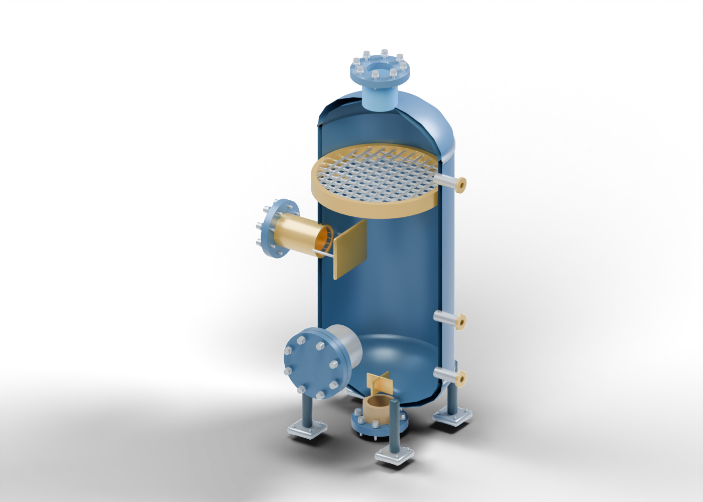
Vertical separator wall
Hollow enclosure with five actual side openings. Invented proportions and thickness; no pressure-vessel design.
Upper curved head
Original hollow upper-head shape with a central gas opening. No standard head geometry, reinforcement or pressure rating.
Lower curved head
Original hollow lower-head shape with a central liquid opening. No rated drain junction or fabrication.
Upper seam marker
Separate seam-location marker. No weld preparation or inspection evidence.
Lower seam marker
Separate seam-location marker. No weld or stress qualification.
Mixed-feed inlet neck
Separate hollow connection aligned with a real enclosure opening. No rated weld, reinforcement, service or measured value.
Mixed-feed flange
Separate annular inlet flange with eight actual stud bores. No rated class or facing.
Feed joint stud 1
Separate smooth stud marker through an actual joint bore. No threads, preload or rated retention.
Feed joint washer 1
Separate bored washer marker; no qualified fastener loads.
Feed joint nut 1
Separate unthreaded circular nut marker; no torque or rated attachment.
Feed joint stud 2
Separate smooth stud marker through an actual joint bore. No threads, preload or rated retention.
Feed joint washer 2
Separate bored washer marker; no qualified fastener loads.
Feed joint nut 2
Separate unthreaded circular nut marker; no torque or rated attachment.
Feed joint stud 3
Separate smooth stud marker through an actual joint bore. No threads, preload or rated retention.
Feed joint washer 3
Separate bored washer marker; no qualified fastener loads.
Feed joint nut 3
Separate unthreaded circular nut marker; no torque or rated attachment.
Feed joint stud 4
Separate smooth stud marker through an actual joint bore. No threads, preload or rated retention.
Feed joint washer 4
Separate bored washer marker; no qualified fastener loads.
Feed joint nut 4
Separate unthreaded circular nut marker; no torque or rated attachment.
Feed joint stud 5
Separate smooth stud marker through an actual joint bore. No threads, preload or rated retention.
Feed joint washer 5
Separate bored washer marker; no qualified fastener loads.
Feed joint nut 5
Separate unthreaded circular nut marker; no torque or rated attachment.
Feed joint stud 6
Separate smooth stud marker through an actual joint bore. No threads, preload or rated retention.
Feed joint washer 6
Separate bored washer marker; no qualified fastener loads.
Feed joint nut 6
Separate unthreaded circular nut marker; no torque or rated attachment.
Feed joint stud 7
Separate smooth stud marker through an actual joint bore. No threads, preload or rated retention.
Feed joint washer 7
Separate bored washer marker; no qualified fastener loads.
Feed joint nut 7
Separate unthreaded circular nut marker; no torque or rated attachment.
Feed joint stud 8
Separate smooth stud marker through an actual joint bore. No threads, preload or rated retention.
Feed joint washer 8
Separate bored washer marker; no qualified fastener loads.
Feed joint nut 8
Separate unthreaded circular nut marker; no torque or rated attachment.
Inlet deflector
Original flat deflector region beyond the inlet opening. No flow distribution, impact, separation or erosion simulation.
Deflector support -0.3
Separate support-location marker. No attachment or load qualification.
Deflector support 0.3
Separate support-location marker. No attachment or load qualification.
Gas outlet neck
Open upper process neck aligned with the head aperture. Bulk gas outlet label, not a dehydration or measured-quality result.
Gas outlet flange
Open annular gas flange with eight actual stud bores. No downstream pipe or qualified pressure joint.
Gas joint stud 1
Separate smooth stud marker through an actual joint bore. No threads, preload or rated retention.
Gas joint washer 1
Separate bored washer marker; no qualified fastener loads.
Gas joint nut 1
Separate unthreaded circular nut marker; no torque or rated attachment.
Gas joint stud 2
Separate smooth stud marker through an actual joint bore. No threads, preload or rated retention.
Gas joint washer 2
Separate bored washer marker; no qualified fastener loads.
Gas joint nut 2
Separate unthreaded circular nut marker; no torque or rated attachment.
Gas joint stud 3
Separate smooth stud marker through an actual joint bore. No threads, preload or rated retention.
Gas joint washer 3
Separate bored washer marker; no qualified fastener loads.
Gas joint nut 3
Separate unthreaded circular nut marker; no torque or rated attachment.
Gas joint stud 4
Separate smooth stud marker through an actual joint bore. No threads, preload or rated retention.
Gas joint washer 4
Separate bored washer marker; no qualified fastener loads.
Gas joint nut 4
Separate unthreaded circular nut marker; no torque or rated attachment.
Gas joint stud 5
Separate smooth stud marker through an actual joint bore. No threads, preload or rated retention.
Gas joint washer 5
Separate bored washer marker; no qualified fastener loads.
Gas joint nut 5
Separate unthreaded circular nut marker; no torque or rated attachment.
Gas joint stud 6
Separate smooth stud marker through an actual joint bore. No threads, preload or rated retention.
Gas joint washer 6
Separate bored washer marker; no qualified fastener loads.
Gas joint nut 6
Separate unthreaded circular nut marker; no torque or rated attachment.
Gas joint stud 7
Separate smooth stud marker through an actual joint bore. No threads, preload or rated retention.
Gas joint washer 7
Separate bored washer marker; no qualified fastener loads.
Gas joint nut 7
Separate unthreaded circular nut marker; no torque or rated attachment.
Gas joint stud 8
Separate smooth stud marker through an actual joint bore. No threads, preload or rated retention.
Gas joint washer 8
Separate bored washer marker; no qualified fastener loads.
Gas joint nut 8
Separate unthreaded circular nut marker; no torque or rated attachment.
Total-liquid outlet neck
Open lower process neck. Total liquid is not separated into oil and water in this concept.
Total-liquid outlet flange
Separate lower flange with eight actual stud bores. No dump valve, control logic or disposal destination.
Liquid joint stud 1
Separate smooth stud marker through an actual joint bore. No threads, preload or rated retention.
Liquid joint washer 1
Separate bored washer marker; no qualified fastener loads.
Liquid joint nut 1
Separate unthreaded circular nut marker; no torque or rated attachment.
Liquid joint stud 2
Separate smooth stud marker through an actual joint bore. No threads, preload or rated retention.
Liquid joint washer 2
Separate bored washer marker; no qualified fastener loads.
Liquid joint nut 2
Separate unthreaded circular nut marker; no torque or rated attachment.
Liquid joint stud 3
Separate smooth stud marker through an actual joint bore. No threads, preload or rated retention.
Liquid joint washer 3
Separate bored washer marker; no qualified fastener loads.
Liquid joint nut 3
Separate unthreaded circular nut marker; no torque or rated attachment.
Liquid joint stud 4
Separate smooth stud marker through an actual joint bore. No threads, preload or rated retention.
Liquid joint washer 4
Separate bored washer marker; no qualified fastener loads.
Liquid joint nut 4
Separate unthreaded circular nut marker; no torque or rated attachment.
Liquid joint stud 5
Separate smooth stud marker through an actual joint bore. No threads, preload or rated retention.
Liquid joint washer 5
Separate bored washer marker; no qualified fastener loads.
Liquid joint nut 5
Separate unthreaded circular nut marker; no torque or rated attachment.
Liquid joint stud 6
Separate smooth stud marker through an actual joint bore. No threads, preload or rated retention.
Liquid joint washer 6
Separate bored washer marker; no qualified fastener loads.
Liquid joint nut 6
Separate unthreaded circular nut marker; no torque or rated attachment.
Liquid joint stud 7
Separate smooth stud marker through an actual joint bore. No threads, preload or rated retention.
Liquid joint washer 7
Separate bored washer marker; no qualified fastener loads.
Liquid joint nut 7
Separate unthreaded circular nut marker; no torque or rated attachment.
Liquid joint stud 8
Separate smooth stud marker through an actual joint bore. No threads, preload or rated retention.
Liquid joint washer 8
Separate bored washer marker; no qualified fastener loads.
Liquid joint nut 8
Separate unthreaded circular nut marker; no torque or rated attachment.
Manway neck
Separate hollow connection aligned with a real enclosure opening. No rated weld, reinforcement, service or measured value.
Manway flange
Annular service-opening flange. No opening, entry or maintenance instruction.
Manway gasket marker
Separate bored gasket marker. No material, compression or sealing result.
Closed manway cover
Separate solid cover in a closed static position. No pressure qualification or entry procedure.
Manway joint stud 1
Separate smooth stud marker through an actual joint bore. No threads, preload or rated retention.
Manway joint washer 1
Separate bored washer marker; no qualified fastener loads.
Manway joint nut 1
Separate unthreaded circular nut marker; no torque or rated attachment.
Manway joint stud 2
Separate smooth stud marker through an actual joint bore. No threads, preload or rated retention.
Manway joint washer 2
Separate bored washer marker; no qualified fastener loads.
Manway joint nut 2
Separate unthreaded circular nut marker; no torque or rated attachment.
Manway joint stud 3
Separate smooth stud marker through an actual joint bore. No threads, preload or rated retention.
Manway joint washer 3
Separate bored washer marker; no qualified fastener loads.
Manway joint nut 3
Separate unthreaded circular nut marker; no torque or rated attachment.
Manway joint stud 4
Separate smooth stud marker through an actual joint bore. No threads, preload or rated retention.
Manway joint washer 4
Separate bored washer marker; no qualified fastener loads.
Manway joint nut 4
Separate unthreaded circular nut marker; no torque or rated attachment.
Manway joint stud 5
Separate smooth stud marker through an actual joint bore. No threads, preload or rated retention.
Manway joint washer 5
Separate bored washer marker; no qualified fastener loads.
Manway joint nut 5
Separate unthreaded circular nut marker; no torque or rated attachment.
Manway joint stud 6
Separate smooth stud marker through an actual joint bore. No threads, preload or rated retention.
Manway joint washer 6
Separate bored washer marker; no qualified fastener loads.
Manway joint nut 6
Separate unthreaded circular nut marker; no torque or rated attachment.
Manway joint stud 7
Separate smooth stud marker through an actual joint bore. No threads, preload or rated retention.
Manway joint washer 7
Separate bored washer marker; no qualified fastener loads.
Manway joint nut 7
Separate unthreaded circular nut marker; no torque or rated attachment.
Manway joint stud 8
Separate smooth stud marker through an actual joint bore. No threads, preload or rated retention.
Manway joint washer 8
Separate bored washer marker; no qualified fastener loads.
Manway joint nut 8
Separate unthreaded circular nut marker; no torque or rated attachment.
Lower level tapping neck
Separate hollow connection aligned with a real enclosure opening. No rated weld, reinforcement, service or measured value.
Lower level tapping boundary ring
Open instrument-boundary ring. No sensor, displayed reading, calibration or control loop.
Upper level tapping neck
Separate hollow connection aligned with a real enclosure opening. No rated weld, reinforcement, service or measured value.
Upper level tapping boundary ring
Open instrument-boundary ring. No sensor, displayed reading, calibration or control loop.
Pressure tapping neck
Separate hollow connection aligned with a real enclosure opening. No rated weld, reinforcement, service or measured value.
Pressure tapping boundary ring
Open instrument-boundary ring. No sensor, displayed reading, calibration or control loop.
Mist-pad carrier ring
Separate support ring around an open lattice teaching region. No bypass seal, drainage or mist-removal performance.
Mist lattice layer 1 member 1
Individual straight lattice member. Open crossed layers illustrate a mist-pad region, not a knitted wire specification or capture efficiency.
Mist lattice layer 1 member 2
Individual straight lattice member. Open crossed layers illustrate a mist-pad region, not a knitted wire specification or capture efficiency.
Mist lattice layer 1 member 3
Individual straight lattice member. Open crossed layers illustrate a mist-pad region, not a knitted wire specification or capture efficiency.
Mist lattice layer 1 member 4
Individual straight lattice member. Open crossed layers illustrate a mist-pad region, not a knitted wire specification or capture efficiency.
Mist lattice layer 1 member 5
Individual straight lattice member. Open crossed layers illustrate a mist-pad region, not a knitted wire specification or capture efficiency.
Mist lattice layer 1 member 6
Individual straight lattice member. Open crossed layers illustrate a mist-pad region, not a knitted wire specification or capture efficiency.
Mist lattice layer 1 member 7
Individual straight lattice member. Open crossed layers illustrate a mist-pad region, not a knitted wire specification or capture efficiency.
Mist lattice layer 1 member 8
Individual straight lattice member. Open crossed layers illustrate a mist-pad region, not a knitted wire specification or capture efficiency.
Mist lattice layer 1 member 9
Individual straight lattice member. Open crossed layers illustrate a mist-pad region, not a knitted wire specification or capture efficiency.
Mist lattice layer 1 member 10
Individual straight lattice member. Open crossed layers illustrate a mist-pad region, not a knitted wire specification or capture efficiency.
Mist lattice layer 1 member 11
Individual straight lattice member. Open crossed layers illustrate a mist-pad region, not a knitted wire specification or capture efficiency.
Mist lattice layer 2 member 1
Individual straight lattice member. Open crossed layers illustrate a mist-pad region, not a knitted wire specification or capture efficiency.
Mist lattice layer 2 member 2
Individual straight lattice member. Open crossed layers illustrate a mist-pad region, not a knitted wire specification or capture efficiency.
Mist lattice layer 2 member 3
Individual straight lattice member. Open crossed layers illustrate a mist-pad region, not a knitted wire specification or capture efficiency.
Mist lattice layer 2 member 4
Individual straight lattice member. Open crossed layers illustrate a mist-pad region, not a knitted wire specification or capture efficiency.
Mist lattice layer 2 member 5
Individual straight lattice member. Open crossed layers illustrate a mist-pad region, not a knitted wire specification or capture efficiency.
Mist lattice layer 2 member 6
Individual straight lattice member. Open crossed layers illustrate a mist-pad region, not a knitted wire specification or capture efficiency.
Mist lattice layer 2 member 7
Individual straight lattice member. Open crossed layers illustrate a mist-pad region, not a knitted wire specification or capture efficiency.
Mist lattice layer 2 member 8
Individual straight lattice member. Open crossed layers illustrate a mist-pad region, not a knitted wire specification or capture efficiency.
Mist lattice layer 2 member 9
Individual straight lattice member. Open crossed layers illustrate a mist-pad region, not a knitted wire specification or capture efficiency.
Mist lattice layer 2 member 10
Individual straight lattice member. Open crossed layers illustrate a mist-pad region, not a knitted wire specification or capture efficiency.
Mist lattice layer 2 member 11
Individual straight lattice member. Open crossed layers illustrate a mist-pad region, not a knitted wire specification or capture efficiency.
Mist lattice layer 3 member 1
Individual straight lattice member. Open crossed layers illustrate a mist-pad region, not a knitted wire specification or capture efficiency.
Mist lattice layer 3 member 2
Individual straight lattice member. Open crossed layers illustrate a mist-pad region, not a knitted wire specification or capture efficiency.
Mist lattice layer 3 member 3
Individual straight lattice member. Open crossed layers illustrate a mist-pad region, not a knitted wire specification or capture efficiency.
Mist lattice layer 3 member 4
Individual straight lattice member. Open crossed layers illustrate a mist-pad region, not a knitted wire specification or capture efficiency.
Mist lattice layer 3 member 5
Individual straight lattice member. Open crossed layers illustrate a mist-pad region, not a knitted wire specification or capture efficiency.
Mist lattice layer 3 member 6
Individual straight lattice member. Open crossed layers illustrate a mist-pad region, not a knitted wire specification or capture efficiency.
Mist lattice layer 3 member 7
Individual straight lattice member. Open crossed layers illustrate a mist-pad region, not a knitted wire specification or capture efficiency.
Mist lattice layer 3 member 8
Individual straight lattice member. Open crossed layers illustrate a mist-pad region, not a knitted wire specification or capture efficiency.
Mist lattice layer 3 member 9
Individual straight lattice member. Open crossed layers illustrate a mist-pad region, not a knitted wire specification or capture efficiency.
Mist lattice layer 3 member 10
Individual straight lattice member. Open crossed layers illustrate a mist-pad region, not a knitted wire specification or capture efficiency.
Mist lattice layer 3 member 11
Individual straight lattice member. Open crossed layers illustrate a mist-pad region, not a knitted wire specification or capture efficiency.
Mist lattice layer 4 member 1
Individual straight lattice member. Open crossed layers illustrate a mist-pad region, not a knitted wire specification or capture efficiency.
Mist lattice layer 4 member 2
Individual straight lattice member. Open crossed layers illustrate a mist-pad region, not a knitted wire specification or capture efficiency.
Mist lattice layer 4 member 3
Individual straight lattice member. Open crossed layers illustrate a mist-pad region, not a knitted wire specification or capture efficiency.
Mist lattice layer 4 member 4
Individual straight lattice member. Open crossed layers illustrate a mist-pad region, not a knitted wire specification or capture efficiency.
Mist lattice layer 4 member 5
Individual straight lattice member. Open crossed layers illustrate a mist-pad region, not a knitted wire specification or capture efficiency.
Mist lattice layer 4 member 6
Individual straight lattice member. Open crossed layers illustrate a mist-pad region, not a knitted wire specification or capture efficiency.
Mist lattice layer 4 member 7
Individual straight lattice member. Open crossed layers illustrate a mist-pad region, not a knitted wire specification or capture efficiency.
Mist lattice layer 4 member 8
Individual straight lattice member. Open crossed layers illustrate a mist-pad region, not a knitted wire specification or capture efficiency.
Mist lattice layer 4 member 9
Individual straight lattice member. Open crossed layers illustrate a mist-pad region, not a knitted wire specification or capture efficiency.
Mist lattice layer 4 member 10
Individual straight lattice member. Open crossed layers illustrate a mist-pad region, not a knitted wire specification or capture efficiency.
Mist lattice layer 4 member 11
Individual straight lattice member. Open crossed layers illustrate a mist-pad region, not a knitted wire specification or capture efficiency.
Mist-pad support tab -0.67
Separate pad support marker. No retainer-load or vibration qualification.
Mist-pad support tab 0.67
Separate pad support marker. No retainer-load or vibration qualification.
Outlet breaker X plate
Open cross-plate marker above liquid draw-off. No vortex, gas-entrainment or hydraulic result.
Outlet breaker Y plate
Second perpendicular cross-plate marker. No qualified vortex-breaker geometry.
Illustrative total-liquid region
Static coloured teaching volume: total liquid, with no separate oil/water interface, level measurement or process simulation.
Support leg -0.7 -0.7
Illustrative support leg. No structural, anchorage or foundation design.
Support foot -0.7 -0.7
Separate foot marker with four actual anchor holes. No load or site design.
Foot anchor -0.7 -0.7 1
Separate smooth anchor-position marker through a bored foot. No embedment, thread or foundation qualification.
Foot anchor -0.7 -0.7 2
Separate smooth anchor-position marker through a bored foot. No embedment, thread or foundation qualification.
Foot anchor -0.7 -0.7 3
Separate smooth anchor-position marker through a bored foot. No embedment, thread or foundation qualification.
Foot anchor -0.7 -0.7 4
Separate smooth anchor-position marker through a bored foot. No embedment, thread or foundation qualification.
Support leg -0.7 0.7
Illustrative support leg. No structural, anchorage or foundation design.
Support foot -0.7 0.7
Separate foot marker with four actual anchor holes. No load or site design.
Foot anchor -0.7 0.7 1
Separate smooth anchor-position marker through a bored foot. No embedment, thread or foundation qualification.
Foot anchor -0.7 0.7 2
Separate smooth anchor-position marker through a bored foot. No embedment, thread or foundation qualification.
Foot anchor -0.7 0.7 3
Separate smooth anchor-position marker through a bored foot. No embedment, thread or foundation qualification.
Foot anchor -0.7 0.7 4
Separate smooth anchor-position marker through a bored foot. No embedment, thread or foundation qualification.
Support leg 0.7 -0.7
Illustrative support leg. No structural, anchorage or foundation design.
Support foot 0.7 -0.7
Separate foot marker with four actual anchor holes. No load or site design.
Foot anchor 0.7 -0.7 1
Separate smooth anchor-position marker through a bored foot. No embedment, thread or foundation qualification.
Foot anchor 0.7 -0.7 2
Separate smooth anchor-position marker through a bored foot. No embedment, thread or foundation qualification.
Foot anchor 0.7 -0.7 3
Separate smooth anchor-position marker through a bored foot. No embedment, thread or foundation qualification.
Foot anchor 0.7 -0.7 4
Separate smooth anchor-position marker through a bored foot. No embedment, thread or foundation qualification.
Support leg 0.7 0.7
Illustrative support leg. No structural, anchorage or foundation design.
Support foot 0.7 0.7
Separate foot marker with four actual anchor holes. No load or site design.
Foot anchor 0.7 0.7 1
Separate smooth anchor-position marker through a bored foot. No embedment, thread or foundation qualification.
Foot anchor 0.7 0.7 2
Separate smooth anchor-position marker through a bored foot. No embedment, thread or foundation qualification.
Foot anchor 0.7 0.7 3
Separate smooth anchor-position marker through a bored foot. No embedment, thread or foundation qualification.
Foot anchor 0.7 0.7 4
Separate smooth anchor-position marker through a bored foot. No embedment, thread or foundation qualification.