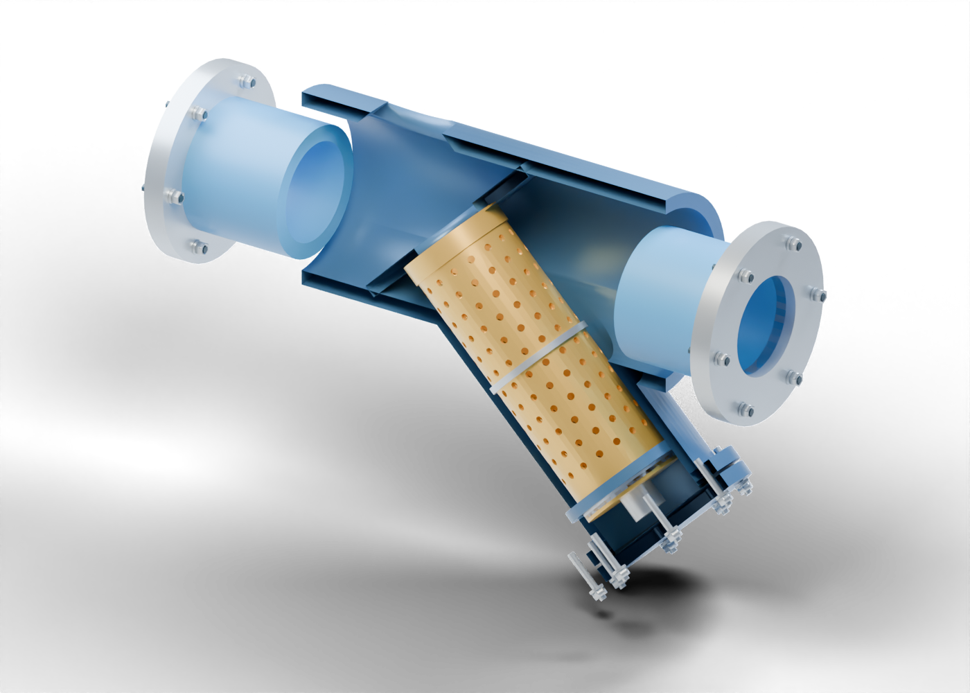
Y housing
One original housing around a horizontal passage and an angled screen pocket. Invented geometry for education; no dimensions, pressure rating, qualified fit, installation or maintenance procedure.
Screen seating partition
Inclined annular web around the screen mouth. This invented arrangement distinguishes an inlet side from the exterior collection space; joints and bypass sealing are unqualified.
Screen mouth collar
Separate open collar aligned with the partition aperture. Retention and seal contact are not qualified.
Perforated screen
Hollow original screen with 192 actual radial perforations. Hole size and geometry are arbitrary, not a filtration grade, mesh designation or retention guarantee.
Screen middle stiffener
Separate circumferential support marker outside the screen, between perforation rows. Strength and attachment are unqualified.
Screen end collar
End collar surrounding the lower edge of the perforated cylinder. No qualified joining detail.
Screen bottom plate
Closed lower end of this screen concept. It prevents the model from depicting a completely open-ended bypass around the screen. Sealing and debris capacity are not calculated.
Pocket screen guide
Stationary annular guide around the lower screen end, with an invented visible clearance. It is not a retention, tolerance or service specification.
Cover support spacer
Generic stationary spacer between the screen end plate and the cover. It is a geometric relationship, not a calculated preload or qualified support.
Pocket cover flange
Open flange around the angled pocket. Bolt pattern and proportions are original teaching geometry.
Pocket gasket
Separate gasket marker between the pocket flange and solid cover. Material, compression and sealing performance are unspecified.
Pocket cover
Solid bolted boundary of the screen pocket. Its separation in the viewer is a visualization, not an opening or cleaning instruction. No drain, blowdown valve or operating arrangement is modelled.
Cover stud 1
Generic smooth cover stud. Thread form, torque, joint load and removal sequence are absent.
Cover washer 1
Separate washer with a geometric stud opening. No rated fastener specification.
Cover nut 1
Separate six-sided nut marker with an unthreaded bore.
Cover stud 2
Generic smooth cover stud. Thread form, torque, joint load and removal sequence are absent.
Cover washer 2
Separate washer with a geometric stud opening. No rated fastener specification.
Cover nut 2
Separate six-sided nut marker with an unthreaded bore.
Cover stud 3
Generic smooth cover stud. Thread form, torque, joint load and removal sequence are absent.
Cover washer 3
Separate washer with a geometric stud opening. No rated fastener specification.
Cover nut 3
Separate six-sided nut marker with an unthreaded bore.
Cover stud 4
Generic smooth cover stud. Thread form, torque, joint load and removal sequence are absent.
Cover washer 4
Separate washer with a geometric stud opening. No rated fastener specification.
Cover nut 4
Separate six-sided nut marker with an unthreaded bore.
Cover stud 5
Generic smooth cover stud. Thread form, torque, joint load and removal sequence are absent.
Cover washer 5
Separate washer with a geometric stud opening. No rated fastener specification.
Cover nut 5
Separate six-sided nut marker with an unthreaded bore.
Cover stud 6
Generic smooth cover stud. Thread form, torque, joint load and removal sequence are absent.
Cover washer 6
Separate washer with a geometric stud opening. No rated fastener specification.
Cover nut 6
Separate six-sided nut marker with an unthreaded bore.
Cover stud 7
Generic smooth cover stud. Thread form, torque, joint load and removal sequence are absent.
Cover washer 7
Separate washer with a geometric stud opening. No rated fastener specification.
Cover nut 7
Separate six-sided nut marker with an unthreaded bore.
Cover stud 8
Generic smooth cover stud. Thread form, torque, joint load and removal sequence are absent.
Cover washer 8
Separate washer with a geometric stud opening. No rated fastener specification.
Cover nut 8
Separate six-sided nut marker with an unthreaded bore.
Inlet neck
Hollow connection into the horizontal housing. Adjoining piping and connection qualification are omitted. Invented geometry for education; no dimensions, pressure rating, qualified fit, installation or maintenance procedure.
Inlet flange
Six-position open connection flange, with original proportions and actual stud bores. No flange standard, face finish or pressure class.
Inlet stud 1
Generic smooth connection stud; no threads, rated joint or torque.
Inlet washer 1
Separate annular washer marker around the stud.
Inlet nut 1
Six-sided nut marker with an unthreaded opening.
Inlet stud 2
Generic smooth connection stud; no threads, rated joint or torque.
Inlet washer 2
Separate annular washer marker around the stud.
Inlet nut 2
Six-sided nut marker with an unthreaded opening.
Inlet stud 3
Generic smooth connection stud; no threads, rated joint or torque.
Inlet washer 3
Separate annular washer marker around the stud.
Inlet nut 3
Six-sided nut marker with an unthreaded opening.
Inlet stud 4
Generic smooth connection stud; no threads, rated joint or torque.
Inlet washer 4
Separate annular washer marker around the stud.
Inlet nut 4
Six-sided nut marker with an unthreaded opening.
Inlet stud 5
Generic smooth connection stud; no threads, rated joint or torque.
Inlet washer 5
Separate annular washer marker around the stud.
Inlet nut 5
Six-sided nut marker with an unthreaded opening.
Inlet stud 6
Generic smooth connection stud; no threads, rated joint or torque.
Inlet washer 6
Separate annular washer marker around the stud.
Inlet nut 6
Six-sided nut marker with an unthreaded opening.
Outlet neck
Hollow connection into the horizontal housing. Adjoining piping and connection qualification are omitted. Invented geometry for education; no dimensions, pressure rating, qualified fit, installation or maintenance procedure.
Outlet flange
Six-position open connection flange, with original proportions and actual stud bores. No flange standard, face finish or pressure class.
Outlet stud 1
Generic smooth connection stud; no threads, rated joint or torque.
Outlet washer 1
Separate annular washer marker around the stud.
Outlet nut 1
Six-sided nut marker with an unthreaded opening.
Outlet stud 2
Generic smooth connection stud; no threads, rated joint or torque.
Outlet washer 2
Separate annular washer marker around the stud.
Outlet nut 2
Six-sided nut marker with an unthreaded opening.
Outlet stud 3
Generic smooth connection stud; no threads, rated joint or torque.
Outlet washer 3
Separate annular washer marker around the stud.
Outlet nut 3
Six-sided nut marker with an unthreaded opening.
Outlet stud 4
Generic smooth connection stud; no threads, rated joint or torque.
Outlet washer 4
Separate annular washer marker around the stud.
Outlet nut 4
Six-sided nut marker with an unthreaded opening.
Outlet stud 5
Generic smooth connection stud; no threads, rated joint or torque.
Outlet washer 5
Separate annular washer marker around the stud.
Outlet nut 5
Six-sided nut marker with an unthreaded opening.
Outlet stud 6
Generic smooth connection stud; no threads, rated joint or torque.
Outlet washer 6
Separate annular washer marker around the stud.
Outlet nut 6
Six-sided nut marker with an unthreaded opening.