
PRODUCTION FACILITY / SIX STOPS / ORIGINAL 3D
Follow the three phase questions.
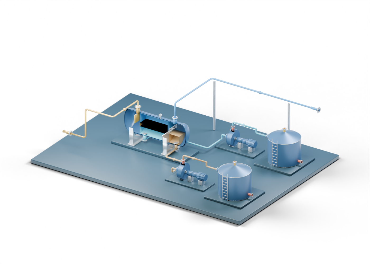
Begin at the separator. Keep oil, water and gas apart.
Six visual stops through an original 424-part surface-facility concept: separate oil, water and gas questions, inspect exact parts, and ask what real evidence is missing.
The 424-part facility and its linked equipment are invented teaching concepts. The six drawn routes are static relationships, not a surveyed facility, process-flow diagram, measured streams or operating instructions.
ONE SCENE / THREE DISTINCT BRANCHES
See where this drawing ends.
The blue and gold render shows a teaching layout. It does not show a built plant or actual fluid motion. Open the scene or a separate detailed component study to inspect named geometry.
Oil question
Oil outlet → transfer-pump concept → oil-tank concept
Water question
Water outlet → separate transfer-pump concept → water-tank concept
Gas question
Gas outlet → open further-handling boundary
The drawing supplies no treating, product-quality, discharge or sales-gas result.
STUDY 01 / 06
Start at the incoming boundary
Find the one drawn route before assuming anything about the real feed.
The colored incoming route reaches the separator shell. It is a static relationship between independently named pieces, not built piping or a measured stream.
A real story needs a facility identity, feed description and reporting period. The scene cannot establish well connections, capacity, pressure, composition or whether an operating plant exists.
PAUSE AND EXPLAIN
Does the colored incoming route establish a built feed line?
Reveal the explanation
No. It is an invented visual relationship. Actual connections and feed conditions require separate facility evidence.
STUDY 02 / 06
Separate three phase questions
Compare the static gas, oil and water regions before following outlets.
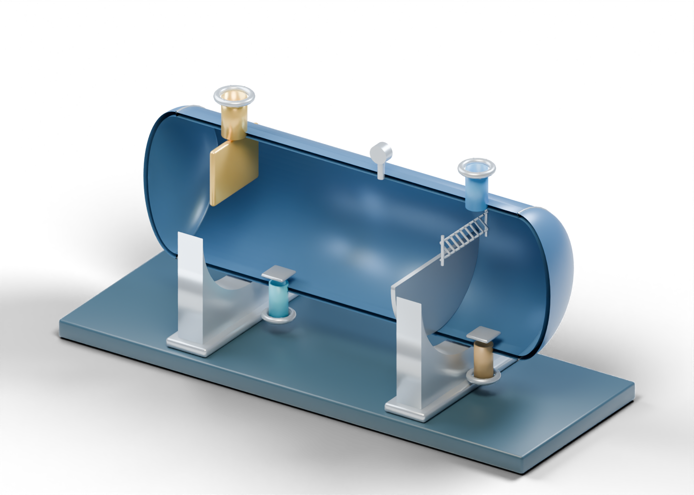
SLB defines a three-phase separator by its gas, oil and water separation roles. In this original scene, the three colored regions are static markers inside the vessel, not fluid calculation or observed interface levels.
Use the separate detailed vessel study to inspect hardware. Neither page proves separation efficiency, residence time, fluid quality or installed controls.
PAUSE AND EXPLAIN
Can three colored regions prove a measured phase split?
Reveal the explanation
No. They distinguish three intended roles in a static teaching model; measured volumes and quality need real records.
STUDY 03 / 06
Follow the oil branch to storage
Identify transfer and storage roles without treating the tank as export-ready oil.
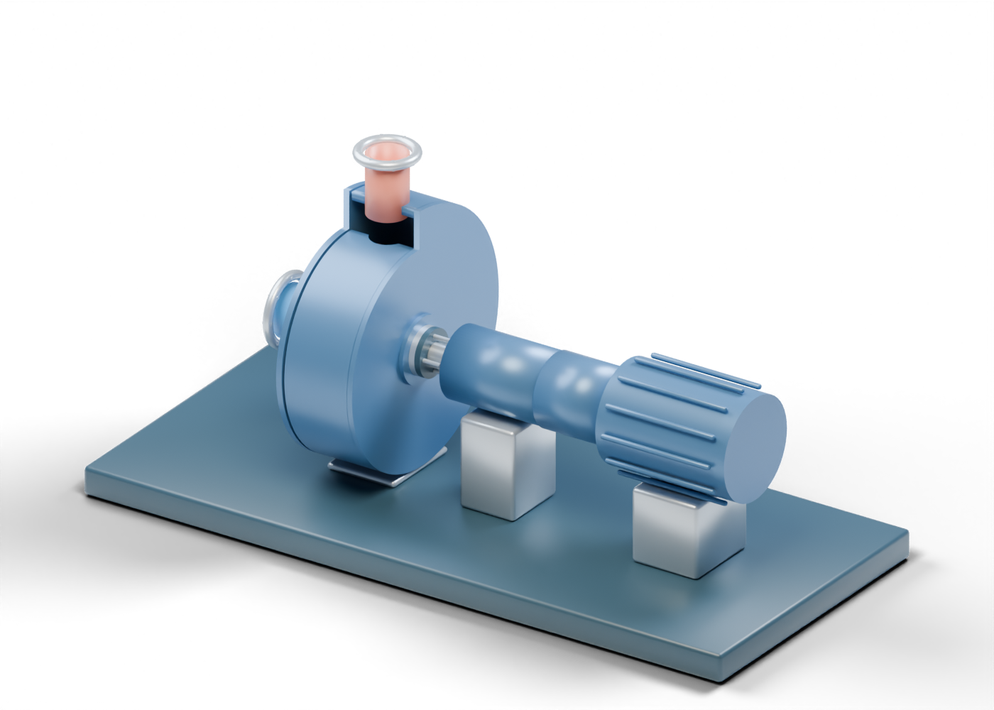
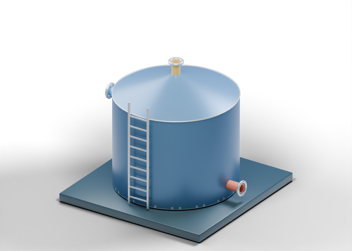
The oil route meets a generic centrifugal-pump instance and then a fixed-roof tank concept. The repeated pump geometry is inspectable; its appearance does not specify a selected pump or duty.
An oil-tank endpoint does not show treating, measurement, vapour control, capacity or an export specification. Ask which real equipment and dated records support any production claim.
PAUSE AND EXPLAIN
Does the oil tank in this scene demonstrate saleable crude?
Reveal the explanation
No. It marks a storage concept. Treatment, quality, measurement and actual disposition are outside the scene.
STUDY 04 / 06
Trace the separate water branch
Keep produced-water handling distinct from the oil route.
A separate route, pump instance and tank represent a produced-water question. The two pump instances reuse a generic model, but their real services could require different selection and protection.
The water tank is an endpoint for reading, not proof of treatment, disposal approval or release quality. The AER storage directive provides a current regulatory starting point; this drawing does not determine compliance.
PAUSE AND EXPLAIN
What does the water-tank endpoint leave unanswered?
Reveal the explanation
Its actual treatment, containment, measurement and approved destination. The static liquid marker proves none of those outcomes.
STUDY 05 / 06
Stop where the gas drawing stops
Recognize the open boundary instead of inventing downstream equipment.
The gas route leaves the separator and ends at an open handling connection. No compressor, treating system, meter, flare or sales line continues from it in this scene.
If a report claims gas delivery or quality, look for actual downstream equipment, measurement and dated evidence. The independently invented gas-compression lesson is a separate illustration, not this facility's missing continuation.
PAUSE AND EXPLAIN
Does the gas connection prove sales-gas delivery?
Reveal the explanation
No. The model deliberately stops before gas handling, measurement and product-quality evidence.
STUDY 06 / 06
Use the picture to interrogate a headline
Turn visible roles into specific questions about the real facility.
AER Directive 017 addresses measurement points and reporting for oil and gas operations. A colored route is not one of those measurements. Identify the reporting date, actual facility, method and source before quoting a volume.
Directive 055 addresses upstream storage requirements. The drawn tanks provide vocabulary, not proof of capacity, containment, venting or compliance. Keep the primary source beside the illustration and distinguish a proposed facility from installed equipment and an observed result.
PAUSE AND EXPLAIN
What would establish a real facility production result?
Reveal the explanation
Attributable, dated measurement and reporting evidence for the actual facility and streams. The original 3D scene supplies only component and relationship vocabulary.
Ask what the illustration cannot tell you.
The exact-part links help identify visible roles; a real facility result requires separate dated records.
| Role | Visible regions | Evidence question | What this illustration lacks |
|---|---|---|---|
| Separator | Shell and three static regions | Which real streams and measurement points are reported? | No phase split, controls or product quality |
| Oil branch | Route, pump instance and tank | What treatment, transfer duty and disposition are documented? | No pump selection, export quality or measured volume |
| Water branch | Independent route, pump and tank | What containment, treatment and destination are documented? | No water quality, disposal approval or capacity |
| Gas boundary | Route ending at an open connection | What handling and measurement follow in reality? | No compression, treatment, metering or sales specification |
Keep the primary source beside the picture.
References checked September 28, 2026. They support general separator vocabulary and point to current Alberta measurement and storage requirements. They do not validate this invented geometry, a real installation or compliance.
- SLB Energy Glossary — three-phase separator ↗
General gas, oil and water role vocabulary only; no product shape or facility proportions adopted.
- Alberta Energy Regulator — Directive 017 ↗
Current measurement and reporting directive page checked September 28, 2026; no compliance claim.
- Alberta Energy Regulator — Directive 055 ↗
Current upstream storage directive page checked September 28, 2026; no facility design or compliance claim.