
PROCESS PLANT STUDY / SIX STOPS
Read a gas-compression train.
Start with the system. Follow the relationships. Open the individual parts.
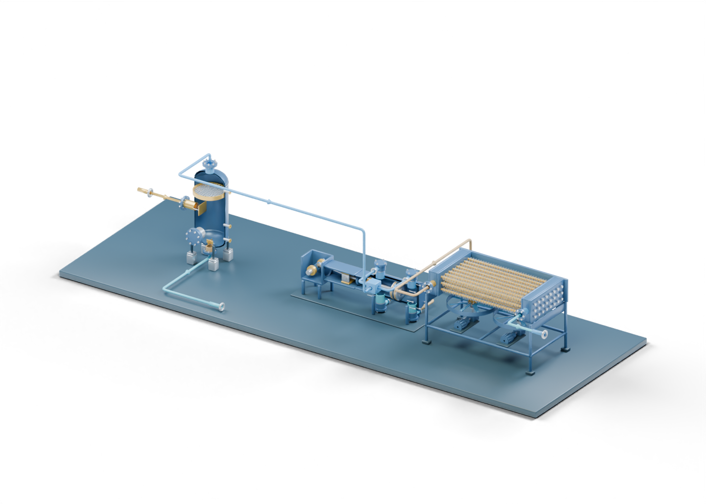
Follow an original connected scene from separation through both compressor ends and aftercooling, then inspect the parts and the evidence behind each claim.
This generic teaching scene connects equipment roles. Study stops are a reading order, not an operating sequence. No certification or personal learning record is created.
SELECT A NODE OR RELATIONSHIP
A map of the original scene.
Each box opens its named component in 3D. The nine numbered relationships below open the corresponding route. These lines follow our scene registry; the diagram is not a piping and instrumentation drawing.
Read all nine relationships and open their exact route
- Incoming stream to inlet separator ↗Incoming gas and liquid boundary → Inlet gas–liquid separator
- Separated gas to suction branches ↗Inlet gas–liquid separator → Suction branch marker
- Crank-end suction relationship ↗Suction branch marker → Double-acting compressor concept
- Head-end suction relationship ↗Suction branch marker → Double-acting compressor concept
- Crank-end discharge relationship ↗Double-acting compressor concept → Discharge branch marker
- Head-end discharge relationship ↗Double-acting compressor concept → Discharge branch marker
- Discharge branches to aftercooler ↗Discharge branch marker → Air-cooled aftercooler concept
- Aftercooler to further-handling boundary ↗Air-cooled aftercooler concept → Further gas treatment and liquid removal — outside model
- Total liquid to handling boundary ↗Inlet gas–liquid separator → Total-liquid handling — outside model
STUDY 01 / 06
Start with the boundaries
Identify what enters, what leaves, and what the drawing leaves outside its scope.
Our teaching scene starts at an incoming gas-and-liquid boundary. It ends at two different boundaries: total-liquid handling below the separator, and further gas handling beyond the cooler. None represents a measured fluid sample or a surveyed plant tie-in.
The map uses eight named nodes and nine declared relationships from the original scene. Two small branch blocks make the compressor's separate end connections legible. They are abstract junction markers, with no fabricated manifold or pulsation equipment design.
PAUSE AND EXPLAIN
Does the incoming boundary tell you the fluid composition or upstream well arrangement?
Reveal the explanation
No. It identifies the edge of this invented scene. Fluid properties, wells and upstream control are outside the model. A boundary label is not an analysis record.
STUDY 02 / 06
Separate the two illustrated destinations
Trace the upper gas relationship and the separate lower total-liquid boundary.
The inlet separator sends its upper relationship toward the suction branch marker. Its lower relationship goes to a different liquid-handling boundary. In this scene, total liquid is not divided into individually measured oil and water products.
Open the inlet deflector in the standalone vessel. Compare that visible shape with the two outlet regions. A selectable deflector establishes geometry; it supplies no removal efficiency, outlet cleanliness or compressor compatibility result.
PAUSE AND EXPLAIN
Can the lower liquid route establish where that liquid is ultimately stored, treated or disposed of?
Reveal the explanation
No. The route ends at an outside-model boundary. Level control, depressurization, storage, treatment and disposal are not represented by that endpoint.
STUDY 03 / 06
Follow both ends of the compressor
Distinguish the crank-end and head-end relationships from a complete operating cycle.
The suction branch marker has two declared connections to the compressor. Two separate discharge relationships then meet the discharge branch marker. Keep those four relationships distinct rather than reading a single line as the entire cylinder arrangement.
SLB's glossary defines the compressor by its pressure-raising role. Our scene illustrates that vocabulary using an original reciprocating assembly. The static crank, crosshead, packing, piston and valve markers do not calculate gas pressure, a valve event, rod load or a complete drive system.
PAUSE AND EXPLAIN
Do the two discharge relationships prove that the valve markers open and close under gas pressure?
Reveal the explanation
No. They encode connections in the teaching scene. The valve stacks and compressor pose are static, with no pressure-driven event or validated cycle.
STUDY 04 / 06
Distinguish process tubes from their surroundings
Find a process tube, its external fins and the air-side cooling context.
The discharge branch marker connects to the original air-cooled exchanger. Its outlet then reaches the further-handling boundary. The scene's route is a declared relationship, not a calculated temperature history.
Open the first tube and then one of its fins. The tube encloses the illustrated process-side passage; the separate fin is outside it. National Gas's UK glossary describes an aftercooler's role after compression. That vocabulary supplies no matched duty, fan performance or Alberta installation result for this model.
PAUSE AND EXPLAIN
Does the cooler's presence establish an outlet temperature or acceptable product quality?
Reveal the explanation
No. The model supplies neither a thermal calculation nor a measured outlet sample. Further liquid removal, treatment, dehydration and measurement remain outside the scene.
STUDY 05 / 06
Keep the missing systems visible
Separate the scene's component detail from the completeness of a plant.
Return to the two outside-model destinations. The liquid endpoint and further-gas endpoint remain separate. Connecting three detailed equipment assemblies does not turn them into a complete process plant.
The scene does not supply protective arrangements, a complete control system, utilities, a matched equipment duty, a material balance or an operating design. Independent coalescer and glycol-contactor lessons explain additional equipment vocabulary; they are not attached or dimensionally matched extensions of this scene.
PAUSE AND EXPLAIN
Would adding an attractive dehydration render prove that this train produces sales-ready gas?
Reveal the explanation
No. A second independent model does not establish a connected, selected and verified installation. A product-quality claim requires evidence for the actual configuration and measured outcome.
STUDY 06 / 06
Read the news claim alongside the model
Identify what a source actually reports before interpreting an equipment illustration.
For an announced project, identify the asset, the project stage, the event date and the result being claimed. A proposal, construction update and measured operating outcome are different records. Keep the primary source and its scope attached to the claim.
Use the atlas to learn component names and declared relationships. Use the project's actual records to assess its configuration and results. This invented scene neither identifies a real Alberta installation nor independently verifies a news report.
PAUSE AND EXPLAIN
What should you look for when an article claims improved gas quality after an equipment upgrade?
Reveal the explanation
Identify the actual equipment and configuration, the reported project stage, and the evidence for the stated outcome. A render or announced plan alone is not a measured quality result.
Keep the sources beside the illustration.
Primary concept references checked September 27, 2026. These sources supply limited role vocabulary; none reviewed or qualified this original model. No source figures, photos, CAD, product dimensions or performance tables were imported.
- SLB: compressor vocabulary ↗
- SLB: public abstract on scrubber liquid-removal roles (2017) ↗
- National Gas: aftercooler glossary, Appendix G (UK context) ↗
SLB's 2017 technical-paper page is a public overview, not a plant-specific result for this scene. The National Gas reference is a UK transmission document; it is used for aftercooler terminology, with no imported limits or Alberta requirements.