No components match your search. Try a shorter part name.
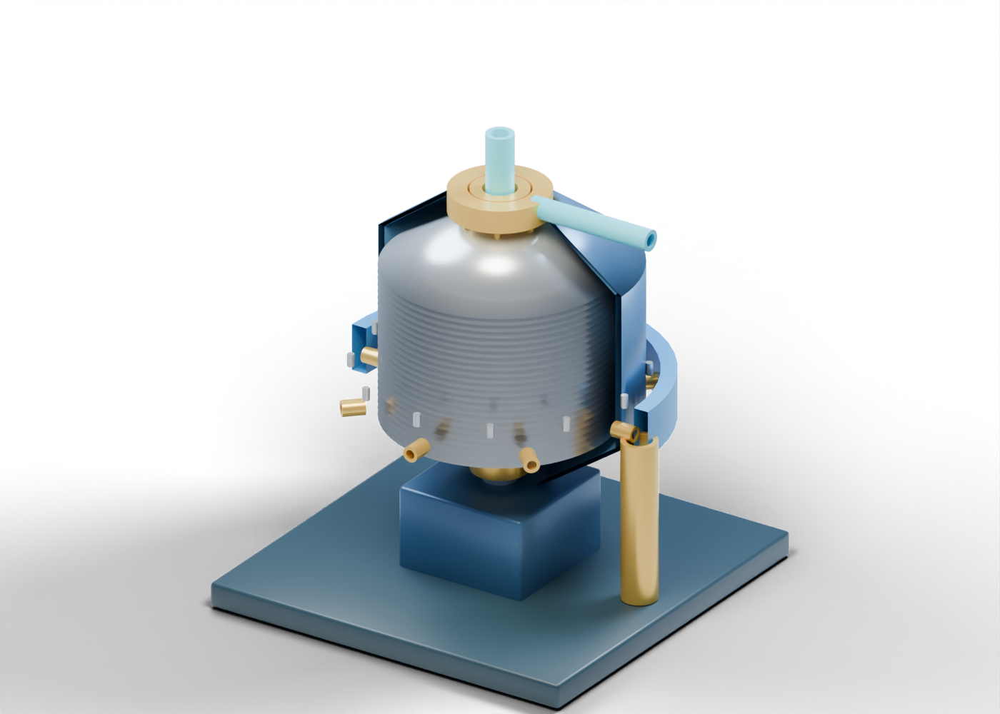
Display plinth
Display base, not an installed foundation.
Drive pedestal
Drive location without an operating motor or transmission.
Central solid spindle
Static spindle supporting the illustrated rotor.
Lower spindle bearing
Separate annular support-region cue.
Complete lower bowl cone
Whole hollow lower rotating bowl.
Complete outer bowl wall
Hollow outer collection region around the disc stack.
Complete upper bowl hood
Whole hollow upper closure; study controls reveal the plates.
Distributor centre tube
Open central distributor illustration; no engineered flow distribution.
Conical separation disc 01
Independent conical plate with an open centre and visible gaps to adjacent plates.
Conical separation disc 02
Independent conical plate with an open centre and visible gaps to adjacent plates.
Conical separation disc 03
Independent conical plate with an open centre and visible gaps to adjacent plates.
Conical separation disc 04
Independent conical plate with an open centre and visible gaps to adjacent plates.
Conical separation disc 05
Independent conical plate with an open centre and visible gaps to adjacent plates.
Conical separation disc 06
Independent conical plate with an open centre and visible gaps to adjacent plates.
Conical separation disc 07
Independent conical plate with an open centre and visible gaps to adjacent plates.
Conical separation disc 08
Independent conical plate with an open centre and visible gaps to adjacent plates.
Conical separation disc 09
Independent conical plate with an open centre and visible gaps to adjacent plates.
Conical separation disc 10
Independent conical plate with an open centre and visible gaps to adjacent plates.
Conical separation disc 11
Independent conical plate with an open centre and visible gaps to adjacent plates.
Conical separation disc 12
Independent conical plate with an open centre and visible gaps to adjacent plates.
Conical separation disc 13
Independent conical plate with an open centre and visible gaps to adjacent plates.
Conical separation disc 14
Independent conical plate with an open centre and visible gaps to adjacent plates.
Conical separation disc 15
Independent conical plate with an open centre and visible gaps to adjacent plates.
Conical separation disc 16
Independent conical plate with an open centre and visible gaps to adjacent plates.
Conical separation disc 17
Independent conical plate with an open centre and visible gaps to adjacent plates.
Conical separation disc 18
Independent conical plate with an open centre and visible gaps to adjacent plates.
Conical separation disc 19
Independent conical plate with an open centre and visible gaps to adjacent plates.
Conical separation disc 20
Independent conical plate with an open centre and visible gaps to adjacent plates.
Conical separation disc 21
Independent conical plate with an open centre and visible gaps to adjacent plates.
Conical separation disc 22
Independent conical plate with an open centre and visible gaps to adjacent plates.
Conical separation disc 23
Independent conical plate with an open centre and visible gaps to adjacent plates.
Conical separation disc 24
Independent conical plate with an open centre and visible gaps to adjacent plates.
Disc support post 1
Invented support location; no clamp-load design.
Disc support post 2
Invented support location; no clamp-load design.
Disc support post 3
Invented support location; no clamp-load design.
Disc support post 4
Invented support location; no clamp-load design.
Disc support post 5
Invented support location; no clamp-load design.
Disc support post 6
Invented support location; no clamp-load design.
Open feed tube
Distinct central feed boundary; not a measured throughput.
Upper liquid collection ring
Annular liquid-collection location outside the central feed tube.
Liquid outlet boundary
Open separate liquid-handling boundary.
Outer solids receiving ring
Separate outer receiving region, not a solids-ejection mechanism.
Peripheral boundary marker 1
Illustrative open radial boundary; no active discharge cycle.
Peripheral boundary marker 2
Illustrative open radial boundary; no active discharge cycle.
Peripheral boundary marker 3
Illustrative open radial boundary; no active discharge cycle.
Peripheral boundary marker 4
Illustrative open radial boundary; no active discharge cycle.
Peripheral boundary marker 5
Illustrative open radial boundary; no active discharge cycle.
Peripheral boundary marker 6
Illustrative open radial boundary; no active discharge cycle.
Peripheral boundary marker 7
Illustrative open radial boundary; no active discharge cycle.
Peripheral boundary marker 8
Illustrative open radial boundary; no active discharge cycle.
Solids handling boundary
Open lower receiving boundary outside the rotor.
Bowl closure marker 1
Separate fastener marker; no pressure or joint qualification.
Bowl closure marker 2
Separate fastener marker; no pressure or joint qualification.
Bowl closure marker 3
Separate fastener marker; no pressure or joint qualification.
Bowl closure marker 4
Separate fastener marker; no pressure or joint qualification.
Bowl closure marker 5
Separate fastener marker; no pressure or joint qualification.
Bowl closure marker 6
Separate fastener marker; no pressure or joint qualification.
Bowl closure marker 7
Separate fastener marker; no pressure or joint qualification.
Bowl closure marker 8
Separate fastener marker; no pressure or joint qualification.
Bowl closure marker 9
Separate fastener marker; no pressure or joint qualification.
Bowl closure marker 10
Separate fastener marker; no pressure or joint qualification.
Bowl closure marker 11
Separate fastener marker; no pressure or joint qualification.
Bowl closure marker 12
Separate fastener marker; no pressure or joint qualification.