No components match your search. Try a shorter part name.
Display skid
Display support, not a structural foundation.
Bearing pedestal -1.9
Static shaft support location.
Bearing outer ring -1.9
Open bearing-region illustration.
Bearing roller -1.9 / 1
Separate display roller; no load rating.
Bearing roller -1.9 / 2
Separate display roller; no load rating.
Bearing roller -1.9 / 3
Separate display roller; no load rating.
Bearing roller -1.9 / 4
Separate display roller; no load rating.
Bearing roller -1.9 / 5
Separate display roller; no load rating.
Bearing roller -1.9 / 6
Separate display roller; no load rating.
Bearing roller -1.9 / 7
Separate display roller; no load rating.
Bearing roller -1.9 / 8
Separate display roller; no load rating.
Bearing pedestal 2.95
Static shaft support location.
Bearing outer ring 2.95
Open bearing-region illustration.
Bearing roller 2.95 / 1
Separate display roller; no load rating.
Bearing roller 2.95 / 2
Separate display roller; no load rating.
Bearing roller 2.95 / 3
Separate display roller; no load rating.
Bearing roller 2.95 / 4
Separate display roller; no load rating.
Bearing roller 2.95 / 5
Separate display roller; no load rating.
Bearing roller 2.95 / 6
Separate display roller; no load rating.
Bearing roller 2.95 / 7
Separate display roller; no load rating.
Bearing roller 2.95 / 8
Separate display roller; no load rating.
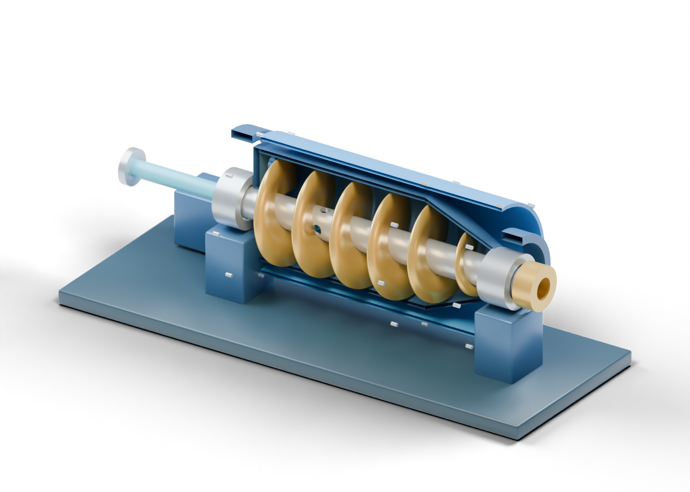
Complete cylindrical rotating bowl
Whole hollow bowl; reveal the internals with the study controls.
Complete conical beach wall
Hollow taper at the solids-conveying end.
Liquid-end annular bowl plate
Annular end plate with six real liquid-opening illustrations.
Solids-end open annulus
Open end boundary around the hub; not a selected discharge arrangement.
Hollow scroll hub
Continuous central bore with four feed-zone openings.
Continuous helical scroll flight
Single continuous invented conveyor flight; pitch and clearances are illustrative.
Stationary feed tube
Open feed-tube illustration inside the central bore.
Feed connection marker
Open unrated feed connection.
Liquid collection enclosure
Separate liquid collection region; the shell is removable for study.
Outer containment enclosure
Whole display guard; no containment or access qualification.
Solids collection enclosure
Distinct solids-end receiving region.
Liquid outlet boundary
Open lower liquid-handling boundary.
Solids outlet boundary
Open lower solids-handling boundary.
Closure fastener -1.53 / 1
Fastener position only; no joint design.
Closure fastener -1.53 / 2
Fastener position only; no joint design.
Closure fastener -1.53 / 3
Fastener position only; no joint design.
Closure fastener -1.53 / 4
Fastener position only; no joint design.
Closure fastener -1.53 / 5
Fastener position only; no joint design.
Closure fastener -1.53 / 6
Fastener position only; no joint design.
Closure fastener -1.53 / 7
Fastener position only; no joint design.
Closure fastener -1.53 / 8
Fastener position only; no joint design.
Closure fastener 1.45 / 1
Fastener position only; no joint design.
Closure fastener 1.45 / 2
Fastener position only; no joint design.
Closure fastener 1.45 / 3
Fastener position only; no joint design.
Closure fastener 1.45 / 4
Fastener position only; no joint design.
Closure fastener 1.45 / 5
Fastener position only; no joint design.
Closure fastener 1.45 / 6
Fastener position only; no joint design.
Closure fastener 1.45 / 7
Fastener position only; no joint design.
Closure fastener 1.45 / 8
Fastener position only; no joint design.
Closure fastener 2.8 / 1
Fastener position only; no joint design.
Closure fastener 2.8 / 2
Fastener position only; no joint design.
Closure fastener 2.8 / 3
Fastener position only; no joint design.
Closure fastener 2.8 / 4
Fastener position only; no joint design.
Closure fastener 2.8 / 5
Fastener position only; no joint design.
Closure fastener 2.8 / 6
Fastener position only; no joint design.
Closure fastener 2.8 / 7
Fastener position only; no joint design.
Closure fastener 2.8 / 8
Fastener position only; no joint design.
Differential-drive interface
Drive-interface location; no transmission or differential-speed simulation.
Main drive boundary
Unconnected driver envelope, not a specified motor.