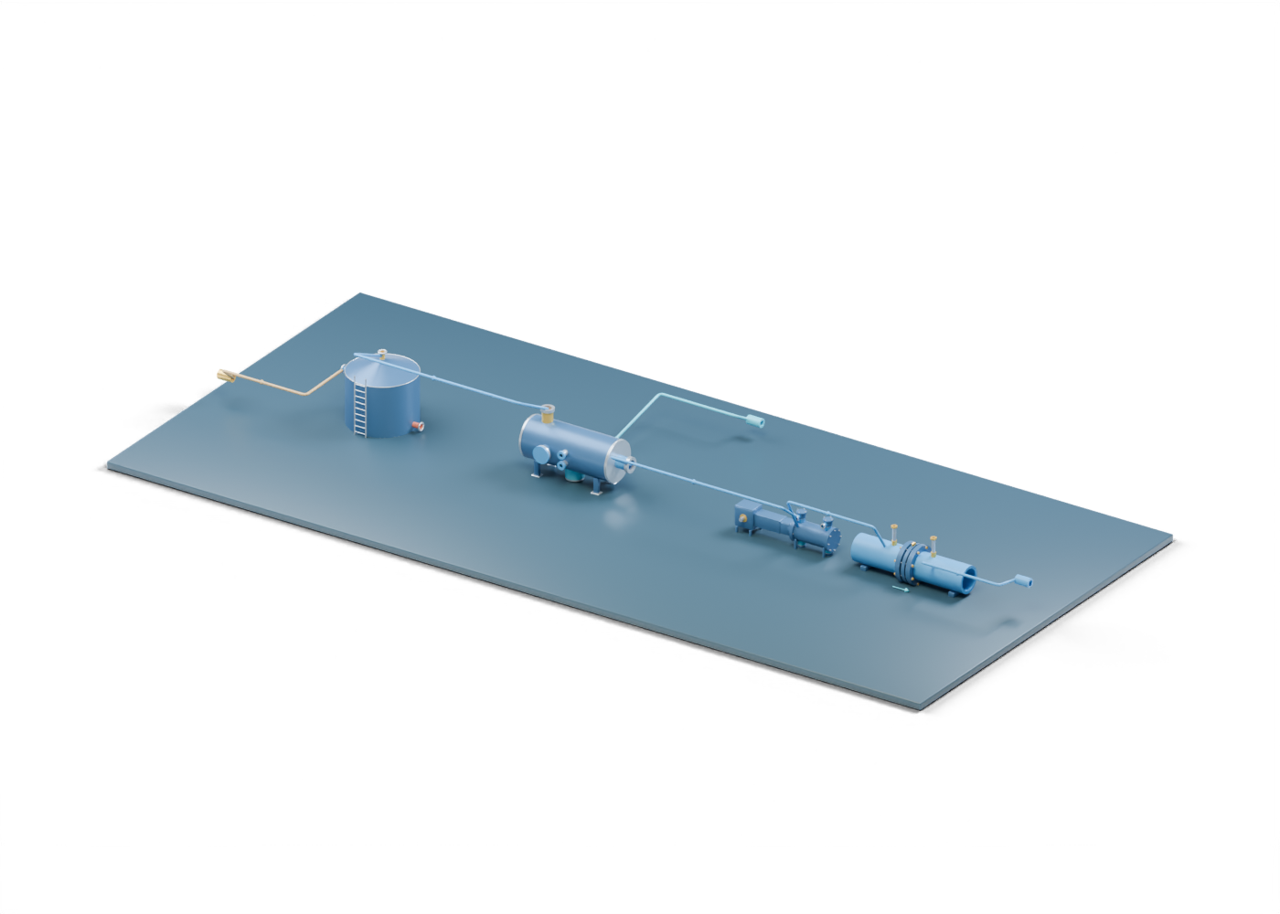
Base frame
Illustrative support frame; foundations and structural design vary.
Crude stock tank / Base frame
Illustrative support frame; foundations and structural design vary. Reused at an invented scale and location; no equipment matching or field selection is implied.
Crude stock tank / Bottom-to-wall joint
Illustrative joint location; no weld design or inspection acceptance criteria. Reused at an invented scale and location; no equipment matching or field selection is implied.
Crude stock tank / Fill connection
Hollow generic connection with illustrative wall thickness. Welds, facing and pressure ratings are not specified. Reused at an invented scale and location; no equipment matching or field selection is implied.
Crude stock tank / Fill connection fastener 1
Generic fastener position. Quantity and size do not specify a rated connection. Reused at an invented scale and location; no equipment matching or field selection is implied.
Crude stock tank / Fill connection fastener 2
Generic fastener position. Quantity and size do not specify a rated connection. Reused at an invented scale and location; no equipment matching or field selection is implied.
Crude stock tank / Fill connection fastener 3
Generic fastener position. Quantity and size do not specify a rated connection. Reused at an invented scale and location; no equipment matching or field selection is implied.
Crude stock tank / Fill connection fastener 4
Generic fastener position. Quantity and size do not specify a rated connection. Reused at an invented scale and location; no equipment matching or field selection is implied.
Crude stock tank / Fill connection fastener 5
Generic fastener position. Quantity and size do not specify a rated connection. Reused at an invented scale and location; no equipment matching or field selection is implied.
Crude stock tank / Fill connection fastener 6
Generic fastener position. Quantity and size do not specify a rated connection. Reused at an invented scale and location; no equipment matching or field selection is implied.
Crude stock tank / Fill connection fastener 7
Generic fastener position. Quantity and size do not specify a rated connection. Reused at an invented scale and location; no equipment matching or field selection is implied.
Crude stock tank / Fill connection fastener 8
Generic fastener position. Quantity and size do not specify a rated connection. Reused at an invented scale and location; no equipment matching or field selection is implied.
Crude stock tank / Fill connection flange
Illustrative flange ring, with no rated facing or bolt specification. Reused at an invented scale and location; no equipment matching or field selection is implied.
Crude stock tank / Fixed roof
Double-surface fixed cone roof with an open vent penetration. Framing, weld design, loads and emergency venting are outside this model. Reused at an invented scale and location; no equipment matching or field selection is implied.
Crude stock tank / Illustrative liquid
Static teaching inventory; not a measured level, capacity or product specification. Reused at an invented scale and location; no equipment matching or field selection is implied.
Crude stock tank / Ladder rail 0.3
Illustrative access ladder; safety systems and required dimensions omitted. Reused at an invented scale and location; no equipment matching or field selection is implied.
Crude stock tank / Ladder rail -0.3
Illustrative access ladder; safety systems and required dimensions omitted. Reused at an invented scale and location; no equipment matching or field selection is implied.
Crude stock tank / Ladder rung 0.5
Schematic ladder rung. Reused at an invented scale and location; no equipment matching or field selection is implied.
Crude stock tank / Ladder rung 0.8
Schematic ladder rung. Reused at an invented scale and location; no equipment matching or field selection is implied.
Crude stock tank / Ladder rung 1.1
Schematic ladder rung. Reused at an invented scale and location; no equipment matching or field selection is implied.
Crude stock tank / Ladder rung 1.4
Schematic ladder rung. Reused at an invented scale and location; no equipment matching or field selection is implied.
Crude stock tank / Ladder rung 1.7
Schematic ladder rung. Reused at an invented scale and location; no equipment matching or field selection is implied.
Crude stock tank / Ladder rung 2
Schematic ladder rung. Reused at an invented scale and location; no equipment matching or field selection is implied.
Crude stock tank / Ladder rung 2.3
Schematic ladder rung. Reused at an invented scale and location; no equipment matching or field selection is implied.
Crude stock tank / Ladder rung 2.6
Schematic ladder rung. Reused at an invented scale and location; no equipment matching or field selection is implied.
Crude stock tank / Ladder rung 2.9
Schematic ladder rung. Reused at an invented scale and location; no equipment matching or field selection is implied.
Crude stock tank / Manway cover
Closed removable-cover concept. Reveal internals hides this cover for learning; the explorer is not an entry or opening procedure. Reused at an invented scale and location; no equipment matching or field selection is implied.
Crude stock tank / Manway gasket
Conceptual gasket location between neck flange and cover; material, compression and leakage performance are unspecified. Reused at an invented scale and location; no equipment matching or field selection is implied.
Crude stock tank / Manway neck
Hollow generic connection with illustrative wall thickness. Welds, facing and pressure ratings are not specified. Reused at an invented scale and location; no equipment matching or field selection is implied.
Crude stock tank / Manway neck fastener 1
Generic fastener position. Quantity and size do not specify a rated connection. Reused at an invented scale and location; no equipment matching or field selection is implied.
Crude stock tank / Manway neck fastener 2
Generic fastener position. Quantity and size do not specify a rated connection. Reused at an invented scale and location; no equipment matching or field selection is implied.
Crude stock tank / Manway neck fastener 3
Generic fastener position. Quantity and size do not specify a rated connection. Reused at an invented scale and location; no equipment matching or field selection is implied.
Crude stock tank / Manway neck fastener 4
Generic fastener position. Quantity and size do not specify a rated connection. Reused at an invented scale and location; no equipment matching or field selection is implied.
Crude stock tank / Manway neck fastener 5
Generic fastener position. Quantity and size do not specify a rated connection. Reused at an invented scale and location; no equipment matching or field selection is implied.
Crude stock tank / Manway neck fastener 6
Generic fastener position. Quantity and size do not specify a rated connection. Reused at an invented scale and location; no equipment matching or field selection is implied.
Crude stock tank / Manway neck fastener 7
Generic fastener position. Quantity and size do not specify a rated connection. Reused at an invented scale and location; no equipment matching or field selection is implied.
Crude stock tank / Manway neck fastener 8
Generic fastener position. Quantity and size do not specify a rated connection. Reused at an invented scale and location; no equipment matching or field selection is implied.
Crude stock tank / Manway neck flange
Illustrative flange ring, with no rated facing or bolt specification. Reused at an invented scale and location; no equipment matching or field selection is implied.
Crude stock tank / Roof-to-wall joint
Illustrative joint location; no weld section or qualified connection. Reused at an invented scale and location; no equipment matching or field selection is implied.
Crude stock tank / Tank floor
Generic bottom plate. Reused at an invented scale and location; no equipment matching or field selection is implied.
Crude stock tank / Tank wall
Generic atmospheric tank wall with geometric fill, withdrawal and manway openings. Thickness and dimensions are illustrative. Reused at an invented scale and location; no equipment matching or field selection is implied.
Crude stock tank / Vent connection
Open geometric vent connection only. Normal and emergency vent devices, vapour handling, sizing and discharge destinations are omitted; this opening is not a complete venting system. Reused at an invented scale and location; no equipment matching or field selection is implied.
Crude stock tank / Vent connection fastener 1
Generic fastener position. Quantity and size do not specify a rated connection. Reused at an invented scale and location; no equipment matching or field selection is implied.
Crude stock tank / Vent connection fastener 2
Generic fastener position. Quantity and size do not specify a rated connection. Reused at an invented scale and location; no equipment matching or field selection is implied.
Crude stock tank / Vent connection fastener 3
Generic fastener position. Quantity and size do not specify a rated connection. Reused at an invented scale and location; no equipment matching or field selection is implied.
Crude stock tank / Vent connection fastener 4
Generic fastener position. Quantity and size do not specify a rated connection. Reused at an invented scale and location; no equipment matching or field selection is implied.
Crude stock tank / Vent connection fastener 5
Generic fastener position. Quantity and size do not specify a rated connection. Reused at an invented scale and location; no equipment matching or field selection is implied.
Crude stock tank / Vent connection fastener 6
Generic fastener position. Quantity and size do not specify a rated connection. Reused at an invented scale and location; no equipment matching or field selection is implied.
Crude stock tank / Vent connection fastener 7
Generic fastener position. Quantity and size do not specify a rated connection. Reused at an invented scale and location; no equipment matching or field selection is implied.
Crude stock tank / Vent connection fastener 8
Generic fastener position. Quantity and size do not specify a rated connection. Reused at an invented scale and location; no equipment matching or field selection is implied.
Crude stock tank / Vent connection flange
Illustrative flange ring, with no rated facing or bolt specification. Reused at an invented scale and location; no equipment matching or field selection is implied.
Crude stock tank / Withdrawal connection
Hollow generic connection with illustrative wall thickness. Welds, facing and pressure ratings are not specified. Reused at an invented scale and location; no equipment matching or field selection is implied.
Crude stock tank / Withdrawal connection fastener 1
Generic fastener position. Quantity and size do not specify a rated connection. Reused at an invented scale and location; no equipment matching or field selection is implied.
Crude stock tank / Withdrawal connection fastener 2
Generic fastener position. Quantity and size do not specify a rated connection. Reused at an invented scale and location; no equipment matching or field selection is implied.
Crude stock tank / Withdrawal connection fastener 3
Generic fastener position. Quantity and size do not specify a rated connection. Reused at an invented scale and location; no equipment matching or field selection is implied.
Crude stock tank / Withdrawal connection fastener 4
Generic fastener position. Quantity and size do not specify a rated connection. Reused at an invented scale and location; no equipment matching or field selection is implied.
Crude stock tank / Withdrawal connection fastener 5
Generic fastener position. Quantity and size do not specify a rated connection. Reused at an invented scale and location; no equipment matching or field selection is implied.
Crude stock tank / Withdrawal connection fastener 6
Generic fastener position. Quantity and size do not specify a rated connection. Reused at an invented scale and location; no equipment matching or field selection is implied.
Crude stock tank / Withdrawal connection fastener 7
Generic fastener position. Quantity and size do not specify a rated connection. Reused at an invented scale and location; no equipment matching or field selection is implied.
Crude stock tank / Withdrawal connection fastener 8
Generic fastener position. Quantity and size do not specify a rated connection. Reused at an invented scale and location; no equipment matching or field selection is implied.
Crude stock tank / Withdrawal connection flange
Illustrative flange ring, with no rated facing or bolt specification. Reused at an invented scale and location; no equipment matching or field selection is implied.
Suction scrubber / Bored boot lower closure
Separate closure with a real lower drain passage. Generic static teaching geometry; no selected fluid, capture efficiency, pressure rating, level logic, compressor interlock, drain action, material, access or structural design is shown. Reused at an invented scale and location; no equipment matching or field selection is implied.
Suction scrubber / Bored outlet-side vessel cap
End closure with one actual gas-outlet passage. Generic static teaching geometry; no selected fluid, capture efficiency, pressure rating, level logic, compressor interlock, drain action, material, access or structural design is shown. Reused at an invented scale and location; no equipment matching or field selection is implied.
Suction scrubber / Bored support foot 1
Separate foot with an actual anchor opening. Generic static teaching geometry; no selected fluid, capture efficiency, pressure rating, level logic, compressor interlock, drain action, material, access or structural design is shown. Reused at an invented scale and location; no equipment matching or field selection is implied.
Suction scrubber / Bored support foot 2
Separate foot with an actual anchor opening. Generic static teaching geometry; no selected fluid, capture efficiency, pressure rating, level logic, compressor interlock, drain action, material, access or structural design is shown. Reused at an invented scale and location; no equipment matching or field selection is implied.
Suction scrubber / Bored support foot 3
Separate foot with an actual anchor opening. Generic static teaching geometry; no selected fluid, capture efficiency, pressure rating, level logic, compressor interlock, drain action, material, access or structural design is shown. Reused at an invented scale and location; no equipment matching or field selection is implied.
Suction scrubber / Bored support foot 4
Separate foot with an actual anchor opening. Generic static teaching geometry; no selected fluid, capture efficiency, pressure rating, level logic, compressor interlock, drain action, material, access or structural design is shown. Reused at an invented scale and location; no equipment matching or field selection is implied.
Suction scrubber / Closed inlet-side vessel cap
Closed static end, without a selected vessel-head profile. Generic static teaching geometry; no selected fluid, capture efficiency, pressure rating, level logic, compressor interlock, drain action, material, access or structural design is shown. Reused at an invented scale and location; no equipment matching or field selection is implied.
Suction scrubber / Closed inspection cover
Static closed cover; no vessel-entry guidance. Generic static teaching geometry; no selected fluid, capture efficiency, pressure rating, level logic, compressor interlock, drain action, material, access or structural design is shown. Reused at an invented scale and location; no equipment matching or field selection is implied.
Suction scrubber / Closed inspection neck
Side shell opening with a separately closed cover; no access procedure. Generic static teaching geometry; no selected fluid, capture efficiency, pressure rating, level logic, compressor interlock, drain action, material, access or structural design is shown. Reused at an invented scale and location; no equipment matching or field selection is implied.
Suction scrubber / Complete hollow scrubber shell
Complete double-surface horizontal enclosure with five separate wall openings. Generic static teaching geometry; no selected fluid, capture efficiency, pressure rating, level logic, compressor interlock, drain action, material, access or structural design is shown. Reused at an invented scale and location; no equipment matching or field selection is implied.
Suction scrubber / Compressor-side gas outlet hollow neck
Open gas boundary beyond the bored end closure; no connected compressor is depicted. Generic static teaching geometry; no selected fluid, capture efficiency, pressure rating, level logic, compressor interlock, drain action, material, access or structural design is shown. Reused at an invented scale and location; no equipment matching or field selection is implied.
Suction scrubber / Compressor-side gas outlet open collar
Separate open outlet marker, without a rated joint. Generic static teaching geometry; no selected fluid, capture efficiency, pressure rating, level logic, compressor interlock, drain action, material, access or structural design is shown. Reused at an invented scale and location; no equipment matching or field selection is implied.
Suction scrubber / Hollow lower liquid boot
Separate hollow lower collection location meeting an actual shell opening. Generic static teaching geometry; no selected fluid, capture efficiency, pressure rating, level logic, compressor interlock, drain action, material, access or structural design is shown. Reused at an invented scale and location; no equipment matching or field selection is implied.
Suction scrubber / Inlet plate stand-off 0.42
Illustrative location tie, not structural design. Generic static teaching geometry; no selected fluid, capture efficiency, pressure rating, level logic, compressor interlock, drain action, material, access or structural design is shown. Reused at an invented scale and location; no equipment matching or field selection is implied.
Suction scrubber / Inlet plate stand-off -0.42
Illustrative location tie, not structural design. Generic static teaching geometry; no selected fluid, capture efficiency, pressure rating, level logic, compressor interlock, drain action, material, access or structural design is shown. Reused at an invented scale and location; no equipment matching or field selection is implied.
Suction scrubber / Inlet-side seam marker
Visible boundary, not a specified weld. Generic static teaching geometry; no selected fluid, capture efficiency, pressure rating, level logic, compressor interlock, drain action, material, access or structural design is shown. Reused at an invented scale and location; no equipment matching or field selection is implied.
Suction scrubber / Inspection cover seat
Annular location cue, not a selected gasket or flange. Generic static teaching geometry; no selected fluid, capture efficiency, pressure rating, level logic, compressor interlock, drain action, material, access or structural design is shown. Reused at an invented scale and location; no equipment matching or field selection is implied.
Suction scrubber / Lower level-observation hollow neck
Open location only; no gauge, switch, alarm, control or setpoint. Generic static teaching geometry; no selected fluid, capture efficiency, pressure rating, level logic, compressor interlock, drain action, material, access or structural design is shown. Reused at an invented scale and location; no equipment matching or field selection is implied.
Suction scrubber / Lower level-observation open collar
Open marker without instrument selection. Generic static teaching geometry; no selected fluid, capture efficiency, pressure rating, level logic, compressor interlock, drain action, material, access or structural design is shown. Reused at an invented scale and location; no equipment matching or field selection is implied.
Suction scrubber / Mist-pad inlet retainer
Open annular pad-location boundary; no specified packing or seal. Generic static teaching geometry; no selected fluid, capture efficiency, pressure rating, level logic, compressor interlock, drain action, material, access or structural design is shown. Reused at an invented scale and location; no equipment matching or field selection is implied.
Suction scrubber / Mist-pad outlet retainer
Open annular pad-location boundary; no specified packing or seal. Generic static teaching geometry; no selected fluid, capture efficiency, pressure rating, level logic, compressor interlock, drain action, material, access or structural design is shown. Reused at an invented scale and location; no equipment matching or field selection is implied.
Suction scrubber / Mixed-gas inlet hollow neck
Open feed boundary at an actual shell passage. Generic static teaching geometry; no selected fluid, capture efficiency, pressure rating, level logic, compressor interlock, drain action, material, access or structural design is shown. Reused at an invented scale and location; no equipment matching or field selection is implied.
Suction scrubber / Mixed-gas inlet open collar
Separate open connection marker; mating pipe omitted. Generic static teaching geometry; no selected fluid, capture efficiency, pressure rating, level logic, compressor interlock, drain action, material, access or structural design is shown. Reused at an invented scale and location; no equipment matching or field selection is implied.
Suction scrubber / Open mist-weave layer 1 strand 1
One of 24 separate open teaching strands, not specified media or a capture result. Generic static teaching geometry; no selected fluid, capture efficiency, pressure rating, level logic, compressor interlock, drain action, material, access or structural design is shown. Reused at an invented scale and location; no equipment matching or field selection is implied.
Suction scrubber / Open mist-weave layer 1 strand 2
One of 24 separate open teaching strands, not specified media or a capture result. Generic static teaching geometry; no selected fluid, capture efficiency, pressure rating, level logic, compressor interlock, drain action, material, access or structural design is shown. Reused at an invented scale and location; no equipment matching or field selection is implied.
Suction scrubber / Open mist-weave layer 1 strand 3
One of 24 separate open teaching strands, not specified media or a capture result. Generic static teaching geometry; no selected fluid, capture efficiency, pressure rating, level logic, compressor interlock, drain action, material, access or structural design is shown. Reused at an invented scale and location; no equipment matching or field selection is implied.
Suction scrubber / Open mist-weave layer 1 strand 4
One of 24 separate open teaching strands, not specified media or a capture result. Generic static teaching geometry; no selected fluid, capture efficiency, pressure rating, level logic, compressor interlock, drain action, material, access or structural design is shown. Reused at an invented scale and location; no equipment matching or field selection is implied.
Suction scrubber / Open mist-weave layer 1 strand 5
One of 24 separate open teaching strands, not specified media or a capture result. Generic static teaching geometry; no selected fluid, capture efficiency, pressure rating, level logic, compressor interlock, drain action, material, access or structural design is shown. Reused at an invented scale and location; no equipment matching or field selection is implied.
Suction scrubber / Open mist-weave layer 1 strand 6
One of 24 separate open teaching strands, not specified media or a capture result. Generic static teaching geometry; no selected fluid, capture efficiency, pressure rating, level logic, compressor interlock, drain action, material, access or structural design is shown. Reused at an invented scale and location; no equipment matching or field selection is implied.
Suction scrubber / Open mist-weave layer 2 strand 1
One of 24 separate open teaching strands, not specified media or a capture result. Generic static teaching geometry; no selected fluid, capture efficiency, pressure rating, level logic, compressor interlock, drain action, material, access or structural design is shown. Reused at an invented scale and location; no equipment matching or field selection is implied.
Suction scrubber / Open mist-weave layer 2 strand 2
One of 24 separate open teaching strands, not specified media or a capture result. Generic static teaching geometry; no selected fluid, capture efficiency, pressure rating, level logic, compressor interlock, drain action, material, access or structural design is shown. Reused at an invented scale and location; no equipment matching or field selection is implied.
Suction scrubber / Open mist-weave layer 2 strand 3
One of 24 separate open teaching strands, not specified media or a capture result. Generic static teaching geometry; no selected fluid, capture efficiency, pressure rating, level logic, compressor interlock, drain action, material, access or structural design is shown. Reused at an invented scale and location; no equipment matching or field selection is implied.
Suction scrubber / Open mist-weave layer 2 strand 4
One of 24 separate open teaching strands, not specified media or a capture result. Generic static teaching geometry; no selected fluid, capture efficiency, pressure rating, level logic, compressor interlock, drain action, material, access or structural design is shown. Reused at an invented scale and location; no equipment matching or field selection is implied.
Suction scrubber / Open mist-weave layer 2 strand 5
One of 24 separate open teaching strands, not specified media or a capture result. Generic static teaching geometry; no selected fluid, capture efficiency, pressure rating, level logic, compressor interlock, drain action, material, access or structural design is shown. Reused at an invented scale and location; no equipment matching or field selection is implied.
Suction scrubber / Open mist-weave layer 2 strand 6
One of 24 separate open teaching strands, not specified media or a capture result. Generic static teaching geometry; no selected fluid, capture efficiency, pressure rating, level logic, compressor interlock, drain action, material, access or structural design is shown. Reused at an invented scale and location; no equipment matching or field selection is implied.
Suction scrubber / Open mist-weave layer 3 strand 1
One of 24 separate open teaching strands, not specified media or a capture result. Generic static teaching geometry; no selected fluid, capture efficiency, pressure rating, level logic, compressor interlock, drain action, material, access or structural design is shown. Reused at an invented scale and location; no equipment matching or field selection is implied.
Suction scrubber / Open mist-weave layer 3 strand 2
One of 24 separate open teaching strands, not specified media or a capture result. Generic static teaching geometry; no selected fluid, capture efficiency, pressure rating, level logic, compressor interlock, drain action, material, access or structural design is shown. Reused at an invented scale and location; no equipment matching or field selection is implied.
Suction scrubber / Open mist-weave layer 3 strand 3
One of 24 separate open teaching strands, not specified media or a capture result. Generic static teaching geometry; no selected fluid, capture efficiency, pressure rating, level logic, compressor interlock, drain action, material, access or structural design is shown. Reused at an invented scale and location; no equipment matching or field selection is implied.
Suction scrubber / Open mist-weave layer 3 strand 4
One of 24 separate open teaching strands, not specified media or a capture result. Generic static teaching geometry; no selected fluid, capture efficiency, pressure rating, level logic, compressor interlock, drain action, material, access or structural design is shown. Reused at an invented scale and location; no equipment matching or field selection is implied.
Suction scrubber / Open mist-weave layer 3 strand 5
One of 24 separate open teaching strands, not specified media or a capture result. Generic static teaching geometry; no selected fluid, capture efficiency, pressure rating, level logic, compressor interlock, drain action, material, access or structural design is shown. Reused at an invented scale and location; no equipment matching or field selection is implied.
Suction scrubber / Open mist-weave layer 3 strand 6
One of 24 separate open teaching strands, not specified media or a capture result. Generic static teaching geometry; no selected fluid, capture efficiency, pressure rating, level logic, compressor interlock, drain action, material, access or structural design is shown. Reused at an invented scale and location; no equipment matching or field selection is implied.
Suction scrubber / Open mist-weave layer 4 strand 1
One of 24 separate open teaching strands, not specified media or a capture result. Generic static teaching geometry; no selected fluid, capture efficiency, pressure rating, level logic, compressor interlock, drain action, material, access or structural design is shown. Reused at an invented scale and location; no equipment matching or field selection is implied.
Suction scrubber / Open mist-weave layer 4 strand 2
One of 24 separate open teaching strands, not specified media or a capture result. Generic static teaching geometry; no selected fluid, capture efficiency, pressure rating, level logic, compressor interlock, drain action, material, access or structural design is shown. Reused at an invented scale and location; no equipment matching or field selection is implied.
Suction scrubber / Open mist-weave layer 4 strand 3
One of 24 separate open teaching strands, not specified media or a capture result. Generic static teaching geometry; no selected fluid, capture efficiency, pressure rating, level logic, compressor interlock, drain action, material, access or structural design is shown. Reused at an invented scale and location; no equipment matching or field selection is implied.
Suction scrubber / Open mist-weave layer 4 strand 4
One of 24 separate open teaching strands, not specified media or a capture result. Generic static teaching geometry; no selected fluid, capture efficiency, pressure rating, level logic, compressor interlock, drain action, material, access or structural design is shown. Reused at an invented scale and location; no equipment matching or field selection is implied.
Suction scrubber / Open mist-weave layer 4 strand 5
One of 24 separate open teaching strands, not specified media or a capture result. Generic static teaching geometry; no selected fluid, capture efficiency, pressure rating, level logic, compressor interlock, drain action, material, access or structural design is shown. Reused at an invented scale and location; no equipment matching or field selection is implied.
Suction scrubber / Open mist-weave layer 4 strand 6
One of 24 separate open teaching strands, not specified media or a capture result. Generic static teaching geometry; no selected fluid, capture efficiency, pressure rating, level logic, compressor interlock, drain action, material, access or structural design is shown. Reused at an invented scale and location; no equipment matching or field selection is implied.
Suction scrubber / Outlet-side seam marker
Visible boundary, not a specified weld. Generic static teaching geometry; no selected fluid, capture efficiency, pressure rating, level logic, compressor interlock, drain action, material, access or structural design is shown. Reused at an invented scale and location; no equipment matching or field selection is implied.
Suction scrubber / Perforated inlet diversion plate
Possible initial diversion location with six actual holes; no bulk-liquid-removal result. Generic static teaching geometry; no selected fluid, capture efficiency, pressure rating, level logic, compressor interlock, drain action, material, access or structural design is shown. Reused at an invented scale and location; no equipment matching or field selection is implied.
Suction scrubber / Scrubber presentation plinth
Display base, not an installed foundation. Generic static teaching geometry; no selected fluid, capture efficiency, pressure rating, level logic, compressor interlock, drain action, material, access or structural design is shown. Reused at an invented scale and location; no equipment matching or field selection is implied.
Suction scrubber / Separate liquid drain hollow neck
Open lower boundary; valve and destination are outside the scene. Generic static teaching geometry; no selected fluid, capture efficiency, pressure rating, level logic, compressor interlock, drain action, material, access or structural design is shown. Reused at an invented scale and location; no equipment matching or field selection is implied.
Suction scrubber / Separate liquid drain open collar
Open connection marker without a selected valve or line. Generic static teaching geometry; no selected fluid, capture efficiency, pressure rating, level logic, compressor interlock, drain action, material, access or structural design is shown. Reused at an invented scale and location; no equipment matching or field selection is implied.
Suction scrubber / Static lower liquid-region plane
Arbitrary location cue, not a measured liquid level. Generic static teaching geometry; no selected fluid, capture efficiency, pressure rating, level logic, compressor interlock, drain action, material, access or structural design is shown. Reused at an invented scale and location; no equipment matching or field selection is implied.
Suction scrubber / Support stand 1
Illustrative support without load or foundation design. Generic static teaching geometry; no selected fluid, capture efficiency, pressure rating, level logic, compressor interlock, drain action, material, access or structural design is shown. Reused at an invented scale and location; no equipment matching or field selection is implied.
Suction scrubber / Support stand 2
Illustrative support without load or foundation design. Generic static teaching geometry; no selected fluid, capture efficiency, pressure rating, level logic, compressor interlock, drain action, material, access or structural design is shown. Reused at an invented scale and location; no equipment matching or field selection is implied.
Suction scrubber / Support stand 3
Illustrative support without load or foundation design. Generic static teaching geometry; no selected fluid, capture efficiency, pressure rating, level logic, compressor interlock, drain action, material, access or structural design is shown. Reused at an invented scale and location; no equipment matching or field selection is implied.
Suction scrubber / Support stand 4
Illustrative support without load or foundation design. Generic static teaching geometry; no selected fluid, capture efficiency, pressure rating, level logic, compressor interlock, drain action, material, access or structural design is shown. Reused at an invented scale and location; no equipment matching or field selection is implied.
Suction scrubber / Upper level-observation hollow neck
Open location only; no gauge, switch, alarm, control or setpoint. Generic static teaching geometry; no selected fluid, capture efficiency, pressure rating, level logic, compressor interlock, drain action, material, access or structural design is shown. Reused at an invented scale and location; no equipment matching or field selection is implied.
Suction scrubber / Upper level-observation open collar
Open marker without instrument selection. Generic static teaching geometry; no selected fluid, capture efficiency, pressure rating, level logic, compressor interlock, drain action, material, access or structural design is shown. Reused at an invented scale and location; no equipment matching or field selection is implied.
Illustrative compressor / Compression cylinder wall
Actual hollow cylindrical wall with four geometric valve-pocket openings. Invented wall thickness, no gas or pressure simulation. Reused at an invented scale and location; no equipment matching or field selection is implied.
Illustrative compressor / Compressor support frame
Invented support frame. No foundation, structural, vibration or load calculation. Reused at an invented scale and location; no equipment matching or field selection is implied.
Illustrative compressor / Connecting rod big end
Annular connecting-rod end around the crank pin. Split cap, bolts and qualified bearing fit are omitted. Reused at an invented scale and location; no equipment matching or field selection is implied.
Illustrative compressor / Connecting rod shank
Original straight shank joining the two rod-eye regions. Its shape and section are teaching choices. Reused at an invented scale and location; no equipment matching or field selection is implied.
Illustrative compressor / Connecting rod small end
Annular rod end on the crosshead pin axis. No qualified bearing or force transfer. Reused at an invented scale and location; no equipment matching or field selection is implied.
Illustrative compressor / Crank end discharge boundary flange
Open flange marker on the boundary neck; facing, pressure and attachment design omitted. Reused at an invented scale and location; no equipment matching or field selection is implied.
Illustrative compressor / Crank end discharge boundary neck
Hollow boundary connection for the indicated inlet/outlet role. No manifold, support system, gas quantity or process direction simulation. Reused at an invented scale and location; no equipment matching or field selection is implied.
Illustrative compressor / Crank end discharge centre pin
Smooth central guide/attachment marker, without threads or rated valve retention. Reused at an invented scale and location; no equipment matching or field selection is implied.
Illustrative compressor / Crank end discharge cover flange
Annular pocket-cover flange with actual matching stud bores. No rated facing, preload or pressure-joint qualification. Reused at an invented scale and location; no equipment matching or field selection is implied.
Illustrative compressor / Crank end discharge cover nut 1
Bored nut marker. Its circular bore is unthreaded and does not establish retention or torque. Reused at an invented scale and location; no equipment matching or field selection is implied.
Illustrative compressor / Crank end discharge cover nut 2
Bored nut marker. Its circular bore is unthreaded and does not establish retention or torque. Reused at an invented scale and location; no equipment matching or field selection is implied.
Illustrative compressor / Crank end discharge cover nut 3
Bored nut marker. Its circular bore is unthreaded and does not establish retention or torque. Reused at an invented scale and location; no equipment matching or field selection is implied.
Illustrative compressor / Crank end discharge cover nut 4
Bored nut marker. Its circular bore is unthreaded and does not establish retention or torque. Reused at an invented scale and location; no equipment matching or field selection is implied.
Illustrative compressor / Crank end discharge cover stud 1
Smooth stud marker through an actual geometric bore. Threads and qualified bolt load are omitted. Reused at an invented scale and location; no equipment matching or field selection is implied.
Illustrative compressor / Crank end discharge cover stud 2
Smooth stud marker through an actual geometric bore. Threads and qualified bolt load are omitted. Reused at an invented scale and location; no equipment matching or field selection is implied.
Illustrative compressor / Crank end discharge cover stud 3
Smooth stud marker through an actual geometric bore. Threads and qualified bolt load are omitted. Reused at an invented scale and location; no equipment matching or field selection is implied.
Illustrative compressor / Crank end discharge cover stud 4
Smooth stud marker through an actual geometric bore. Threads and qualified bolt load are omitted. Reused at an invented scale and location; no equipment matching or field selection is implied.
Illustrative compressor / Crank end discharge cover washer 1
Separate washer with an open centre. Not a qualified fastener joint. Reused at an invented scale and location; no equipment matching or field selection is implied.
Illustrative compressor / Crank end discharge cover washer 2
Separate washer with an open centre. Not a qualified fastener joint. Reused at an invented scale and location; no equipment matching or field selection is implied.
Illustrative compressor / Crank end discharge cover washer 3
Separate washer with an open centre. Not a qualified fastener joint. Reused at an invented scale and location; no equipment matching or field selection is implied.
Illustrative compressor / Crank end discharge cover washer 4
Separate washer with an open centre. Not a qualified fastener joint. Reused at an invented scale and location; no equipment matching or field selection is implied.
Illustrative compressor / Crank end discharge guard
Separate bored guard/support marker below the plate in this static concept. Retention and valve lift are unspecified. Reused at an invented scale and location; no equipment matching or field selection is implied.
Illustrative compressor / Crank end discharge outer pocket
Hollow outer pocket above the suction seat or below the discharge seat. Separate boundary necks are illustrative, not a complete manifold. Reused at an invented scale and location; no equipment matching or field selection is implied.
Illustrative compressor / Crank end discharge perforated seat
Fixed valve-seat marker with eight actual geometric holes. Not a manufacturer valve or a flow/leakage calculation. Reused at an invented scale and location; no equipment matching or field selection is implied.
Illustrative compressor / Crank end discharge plate marker
Separate annular plate at a fixed illustrated seat relationship. There is no automatic valve event, measured lift, pressure response or leakage result. Reused at an invented scale and location; no equipment matching or field selection is implied.
Illustrative compressor / Crank end discharge pocket cover
Separate solid presentation cover on the outer pocket. No qualified pressure or valve-retention joint. Reused at an invented scale and location; no equipment matching or field selection is implied.
Illustrative compressor / Crank end discharge pocket neck
Hollow connection through a drilled cylinder-wall opening toward a separate valve stack. No rated port or simulated flow. Reused at an invented scale and location; no equipment matching or field selection is implied.
Illustrative compressor / Crank end discharge spring marker
Original three-turn closed coil marker. Static pose; no valve spring rate, preload, fatigue or event timing. Reused at an invented scale and location; no equipment matching or field selection is implied.
Illustrative compressor / Crank end suction boundary flange
Open flange marker on the boundary neck; facing, pressure and attachment design omitted. Reused at an invented scale and location; no equipment matching or field selection is implied.
Illustrative compressor / Crank end suction boundary neck
Hollow boundary connection for the indicated inlet/outlet role. No manifold, support system, gas quantity or process direction simulation. Reused at an invented scale and location; no equipment matching or field selection is implied.
Illustrative compressor / Crank end suction centre pin
Smooth central guide/attachment marker, without threads or rated valve retention. Reused at an invented scale and location; no equipment matching or field selection is implied.
Illustrative compressor / Crank end suction cover flange
Annular pocket-cover flange with actual matching stud bores. No rated facing, preload or pressure-joint qualification. Reused at an invented scale and location; no equipment matching or field selection is implied.
Illustrative compressor / Crank end suction cover nut 1
Bored nut marker. Its circular bore is unthreaded and does not establish retention or torque. Reused at an invented scale and location; no equipment matching or field selection is implied.
Illustrative compressor / Crank end suction cover nut 2
Bored nut marker. Its circular bore is unthreaded and does not establish retention or torque. Reused at an invented scale and location; no equipment matching or field selection is implied.
Illustrative compressor / Crank end suction cover nut 3
Bored nut marker. Its circular bore is unthreaded and does not establish retention or torque. Reused at an invented scale and location; no equipment matching or field selection is implied.
Illustrative compressor / Crank end suction cover nut 4
Bored nut marker. Its circular bore is unthreaded and does not establish retention or torque. Reused at an invented scale and location; no equipment matching or field selection is implied.
Illustrative compressor / Crank end suction cover stud 1
Smooth stud marker through an actual geometric bore. Threads and qualified bolt load are omitted. Reused at an invented scale and location; no equipment matching or field selection is implied.
Illustrative compressor / Crank end suction cover stud 2
Smooth stud marker through an actual geometric bore. Threads and qualified bolt load are omitted. Reused at an invented scale and location; no equipment matching or field selection is implied.
Illustrative compressor / Crank end suction cover stud 3
Smooth stud marker through an actual geometric bore. Threads and qualified bolt load are omitted. Reused at an invented scale and location; no equipment matching or field selection is implied.
Illustrative compressor / Crank end suction cover stud 4
Smooth stud marker through an actual geometric bore. Threads and qualified bolt load are omitted. Reused at an invented scale and location; no equipment matching or field selection is implied.
Illustrative compressor / Crank end suction cover washer 1
Separate washer with an open centre. Not a qualified fastener joint. Reused at an invented scale and location; no equipment matching or field selection is implied.
Illustrative compressor / Crank end suction cover washer 2
Separate washer with an open centre. Not a qualified fastener joint. Reused at an invented scale and location; no equipment matching or field selection is implied.
Illustrative compressor / Crank end suction cover washer 3
Separate washer with an open centre. Not a qualified fastener joint. Reused at an invented scale and location; no equipment matching or field selection is implied.
Illustrative compressor / Crank end suction cover washer 4
Separate washer with an open centre. Not a qualified fastener joint. Reused at an invented scale and location; no equipment matching or field selection is implied.
Illustrative compressor / Crank end suction guard
Separate bored guard/support marker below the plate in this static concept. Retention and valve lift are unspecified. Reused at an invented scale and location; no equipment matching or field selection is implied.
Illustrative compressor / Crank end suction outer pocket
Hollow outer pocket above the suction seat or below the discharge seat. Separate boundary necks are illustrative, not a complete manifold. Reused at an invented scale and location; no equipment matching or field selection is implied.
Illustrative compressor / Crank end suction perforated seat
Fixed valve-seat marker with eight actual geometric holes. Not a manufacturer valve or a flow/leakage calculation. Reused at an invented scale and location; no equipment matching or field selection is implied.
Illustrative compressor / Crank end suction plate marker
Separate annular plate at a fixed illustrated seat relationship. There is no automatic valve event, measured lift, pressure response or leakage result. Reused at an invented scale and location; no equipment matching or field selection is implied.
Illustrative compressor / Crank end suction pocket cover
Separate solid presentation cover on the outer pocket. No qualified pressure or valve-retention joint. Reused at an invented scale and location; no equipment matching or field selection is implied.
Illustrative compressor / Crank end suction pocket neck
Hollow connection through a drilled cylinder-wall opening toward a separate valve stack. No rated port or simulated flow. Reused at an invented scale and location; no equipment matching or field selection is implied.
Illustrative compressor / Crank end suction spring marker
Original three-turn closed coil marker. Static pose; no valve spring rate, preload, fatigue or event timing. Reused at an invented scale and location; no equipment matching or field selection is implied.
Illustrative compressor / Crank-end cylinder flange
Hollow cylinder-end flange with separate drilled fastener bores. Reused at an invented scale and location; no equipment matching or field selection is implied.
Illustrative compressor / Crank-end head
Cylinder closure around the piston rod, with actual central bore. No pressure rating or qualified packing joint. Reused at an invented scale and location; no equipment matching or field selection is implied.
Illustrative compressor / Crank-end joint nut 1
Bored nut marker. Its circular bore is unthreaded and does not establish retention or torque. Reused at an invented scale and location; no equipment matching or field selection is implied.
Illustrative compressor / Crank-end joint nut 2
Bored nut marker. Its circular bore is unthreaded and does not establish retention or torque. Reused at an invented scale and location; no equipment matching or field selection is implied.
Illustrative compressor / Crank-end joint nut 3
Bored nut marker. Its circular bore is unthreaded and does not establish retention or torque. Reused at an invented scale and location; no equipment matching or field selection is implied.
Illustrative compressor / Crank-end joint nut 4
Bored nut marker. Its circular bore is unthreaded and does not establish retention or torque. Reused at an invented scale and location; no equipment matching or field selection is implied.
Illustrative compressor / Crank-end joint nut 5
Bored nut marker. Its circular bore is unthreaded and does not establish retention or torque. Reused at an invented scale and location; no equipment matching or field selection is implied.
Illustrative compressor / Crank-end joint nut 6
Bored nut marker. Its circular bore is unthreaded and does not establish retention or torque. Reused at an invented scale and location; no equipment matching or field selection is implied.
Illustrative compressor / Crank-end joint nut 7
Bored nut marker. Its circular bore is unthreaded and does not establish retention or torque. Reused at an invented scale and location; no equipment matching or field selection is implied.
Illustrative compressor / Crank-end joint nut 8
Bored nut marker. Its circular bore is unthreaded and does not establish retention or torque. Reused at an invented scale and location; no equipment matching or field selection is implied.
Illustrative compressor / Crank-end joint stud 1
Smooth stud marker through an actual geometric bore. Threads and qualified bolt load are omitted. Reused at an invented scale and location; no equipment matching or field selection is implied.
Illustrative compressor / Crank-end joint stud 2
Smooth stud marker through an actual geometric bore. Threads and qualified bolt load are omitted. Reused at an invented scale and location; no equipment matching or field selection is implied.
Illustrative compressor / Crank-end joint stud 3
Smooth stud marker through an actual geometric bore. Threads and qualified bolt load are omitted. Reused at an invented scale and location; no equipment matching or field selection is implied.
Illustrative compressor / Crank-end joint stud 4
Smooth stud marker through an actual geometric bore. Threads and qualified bolt load are omitted. Reused at an invented scale and location; no equipment matching or field selection is implied.
Illustrative compressor / Crank-end joint stud 5
Smooth stud marker through an actual geometric bore. Threads and qualified bolt load are omitted. Reused at an invented scale and location; no equipment matching or field selection is implied.
Illustrative compressor / Crank-end joint stud 6
Smooth stud marker through an actual geometric bore. Threads and qualified bolt load are omitted. Reused at an invented scale and location; no equipment matching or field selection is implied.
Illustrative compressor / Crank-end joint stud 7
Smooth stud marker through an actual geometric bore. Threads and qualified bolt load are omitted. Reused at an invented scale and location; no equipment matching or field selection is implied.
Illustrative compressor / Crank-end joint stud 8
Smooth stud marker through an actual geometric bore. Threads and qualified bolt load are omitted. Reused at an invented scale and location; no equipment matching or field selection is implied.
Illustrative compressor / Crank-end joint washer 1
Separate washer with an open centre. Not a qualified fastener joint. Reused at an invented scale and location; no equipment matching or field selection is implied.
Illustrative compressor / Crank-end joint washer 2
Separate washer with an open centre. Not a qualified fastener joint. Reused at an invented scale and location; no equipment matching or field selection is implied.
Illustrative compressor / Crank-end joint washer 3
Separate washer with an open centre. Not a qualified fastener joint. Reused at an invented scale and location; no equipment matching or field selection is implied.
Illustrative compressor / Crank-end joint washer 4
Separate washer with an open centre. Not a qualified fastener joint. Reused at an invented scale and location; no equipment matching or field selection is implied.
Illustrative compressor / Crank-end joint washer 5
Separate washer with an open centre. Not a qualified fastener joint. Reused at an invented scale and location; no equipment matching or field selection is implied.
Illustrative compressor / Crank-end joint washer 6
Separate washer with an open centre. Not a qualified fastener joint. Reused at an invented scale and location; no equipment matching or field selection is implied.
Illustrative compressor / Crank-end joint washer 7
Separate washer with an open centre. Not a qualified fastener joint. Reused at an invented scale and location; no equipment matching or field selection is implied.
Illustrative compressor / Crank-end joint washer 8
Separate washer with an open centre. Not a qualified fastener joint. Reused at an invented scale and location; no equipment matching or field selection is implied.
Illustrative compressor / Crankcase end wall
Illustrative frame end wall, without qualified casting or ventilation details. Reused at an invented scale and location; no equipment matching or field selection is implied.
Illustrative compressor / Crankcase floor
Static enclosure floor. Oil level, pump and lubrication circuit are omitted. Reused at an invented scale and location; no equipment matching or field selection is implied.
Illustrative compressor / Crankcase guide wall
Frame wall with an actual opening toward the crosshead guide. Reused at an invented scale and location; no equipment matching or field selection is implied.
Illustrative compressor / Crankcase top cover
Separate enclosure cover, removed only by presentation controls. Reused at an invented scale and location; no equipment matching or field selection is implied.
Illustrative compressor / Crosshead pin
Smooth crosshead pin coaxial with the small rod eye. No retention or cyclic load calculation. Reused at an invented scale and location; no equipment matching or field selection is implied.
Illustrative compressor / Crosshead pin bushing
Separate thin bushing marker between the crosshead pin and rod eye. Clearance is invented. Reused at an invented scale and location; no equipment matching or field selection is implied.
Illustrative compressor / Front crank web
Original web marker joining a main journal region to the offset crank pin. No balance or stress qualification. Reused at an invented scale and location; no equipment matching or field selection is implied.
Illustrative compressor / Front crankcase wall
Separate frame wall with a bored crankshaft opening. No pressure or casting specification. Reused at an invented scale and location; no equipment matching or field selection is implied.
Illustrative compressor / Front crosshead cheek
Crosshead side cheek with a real pin bore. Guide and pin relationships are static. Reused at an invented scale and location; no equipment matching or field selection is implied.
Illustrative compressor / Front distance-piece wall
Open-ended distance-piece enclosure marker. Purge, ventilation, drains and service requirements are unspecified. Reused at an invented scale and location; no equipment matching or field selection is implied.
Illustrative compressor / Front guide wall
Separate side enclosure around the crosshead/rod region. Reused at an invented scale and location; no equipment matching or field selection is implied.
Illustrative compressor / Front main bearing
Separate annular bearing marker around the main journal. No oil-film, load or bearing fit qualification. Reused at an invented scale and location; no equipment matching or field selection is implied.
Illustrative compressor / Front main journal
Smooth main journal on the crank axis; no speed, balance or bearing duty. Reused at an invented scale and location; no equipment matching or field selection is implied.
Illustrative compressor / Grooved piston
Original hollow piston marker with two ring recesses and a central rider-band recess. Geometry does not establish a piston material, running clearance or gas performance. Reused at an invented scale and location; no equipment matching or field selection is implied.
Illustrative compressor / Head end discharge boundary flange
Open flange marker on the boundary neck; facing, pressure and attachment design omitted. Reused at an invented scale and location; no equipment matching or field selection is implied.
Illustrative compressor / Head end discharge boundary neck
Hollow boundary connection for the indicated inlet/outlet role. No manifold, support system, gas quantity or process direction simulation. Reused at an invented scale and location; no equipment matching or field selection is implied.
Illustrative compressor / Head end discharge centre pin
Smooth central guide/attachment marker, without threads or rated valve retention. Reused at an invented scale and location; no equipment matching or field selection is implied.
Illustrative compressor / Head end discharge cover flange
Annular pocket-cover flange with actual matching stud bores. No rated facing, preload or pressure-joint qualification. Reused at an invented scale and location; no equipment matching or field selection is implied.
Illustrative compressor / Head end discharge cover nut 1
Bored nut marker. Its circular bore is unthreaded and does not establish retention or torque. Reused at an invented scale and location; no equipment matching or field selection is implied.
Illustrative compressor / Head end discharge cover nut 2
Bored nut marker. Its circular bore is unthreaded and does not establish retention or torque. Reused at an invented scale and location; no equipment matching or field selection is implied.
Illustrative compressor / Head end discharge cover nut 3
Bored nut marker. Its circular bore is unthreaded and does not establish retention or torque. Reused at an invented scale and location; no equipment matching or field selection is implied.
Illustrative compressor / Head end discharge cover nut 4
Bored nut marker. Its circular bore is unthreaded and does not establish retention or torque. Reused at an invented scale and location; no equipment matching or field selection is implied.
Illustrative compressor / Head end discharge cover stud 1
Smooth stud marker through an actual geometric bore. Threads and qualified bolt load are omitted. Reused at an invented scale and location; no equipment matching or field selection is implied.
Illustrative compressor / Head end discharge cover stud 2
Smooth stud marker through an actual geometric bore. Threads and qualified bolt load are omitted. Reused at an invented scale and location; no equipment matching or field selection is implied.
Illustrative compressor / Head end discharge cover stud 3
Smooth stud marker through an actual geometric bore. Threads and qualified bolt load are omitted. Reused at an invented scale and location; no equipment matching or field selection is implied.
Illustrative compressor / Head end discharge cover stud 4
Smooth stud marker through an actual geometric bore. Threads and qualified bolt load are omitted. Reused at an invented scale and location; no equipment matching or field selection is implied.
Illustrative compressor / Head end discharge cover washer 1
Separate washer with an open centre. Not a qualified fastener joint. Reused at an invented scale and location; no equipment matching or field selection is implied.
Illustrative compressor / Head end discharge cover washer 2
Separate washer with an open centre. Not a qualified fastener joint. Reused at an invented scale and location; no equipment matching or field selection is implied.
Illustrative compressor / Head end discharge cover washer 3
Separate washer with an open centre. Not a qualified fastener joint. Reused at an invented scale and location; no equipment matching or field selection is implied.
Illustrative compressor / Head end discharge cover washer 4
Separate washer with an open centre. Not a qualified fastener joint. Reused at an invented scale and location; no equipment matching or field selection is implied.
Illustrative compressor / Head end discharge guard
Separate bored guard/support marker below the plate in this static concept. Retention and valve lift are unspecified. Reused at an invented scale and location; no equipment matching or field selection is implied.
Illustrative compressor / Head end discharge outer pocket
Hollow outer pocket above the suction seat or below the discharge seat. Separate boundary necks are illustrative, not a complete manifold. Reused at an invented scale and location; no equipment matching or field selection is implied.
Illustrative compressor / Head end discharge perforated seat
Fixed valve-seat marker with eight actual geometric holes. Not a manufacturer valve or a flow/leakage calculation. Reused at an invented scale and location; no equipment matching or field selection is implied.
Illustrative compressor / Head end discharge plate marker
Separate annular plate at a fixed illustrated seat relationship. There is no automatic valve event, measured lift, pressure response or leakage result. Reused at an invented scale and location; no equipment matching or field selection is implied.
Illustrative compressor / Head end discharge pocket cover
Separate solid presentation cover on the outer pocket. No qualified pressure or valve-retention joint. Reused at an invented scale and location; no equipment matching or field selection is implied.
Illustrative compressor / Head end discharge pocket neck
Hollow connection through a drilled cylinder-wall opening toward a separate valve stack. No rated port or simulated flow. Reused at an invented scale and location; no equipment matching or field selection is implied.
Illustrative compressor / Head end discharge spring marker
Original three-turn closed coil marker. Static pose; no valve spring rate, preload, fatigue or event timing. Reused at an invented scale and location; no equipment matching or field selection is implied.
Illustrative compressor / Head end suction boundary flange
Open flange marker on the boundary neck; facing, pressure and attachment design omitted. Reused at an invented scale and location; no equipment matching or field selection is implied.
Illustrative compressor / Head end suction boundary neck
Hollow boundary connection for the indicated inlet/outlet role. No manifold, support system, gas quantity or process direction simulation. Reused at an invented scale and location; no equipment matching or field selection is implied.
Illustrative compressor / Head end suction centre pin
Smooth central guide/attachment marker, without threads or rated valve retention. Reused at an invented scale and location; no equipment matching or field selection is implied.
Illustrative compressor / Head end suction cover flange
Annular pocket-cover flange with actual matching stud bores. No rated facing, preload or pressure-joint qualification. Reused at an invented scale and location; no equipment matching or field selection is implied.
Illustrative compressor / Head end suction cover nut 1
Bored nut marker. Its circular bore is unthreaded and does not establish retention or torque. Reused at an invented scale and location; no equipment matching or field selection is implied.
Illustrative compressor / Head end suction cover nut 2
Bored nut marker. Its circular bore is unthreaded and does not establish retention or torque. Reused at an invented scale and location; no equipment matching or field selection is implied.
Illustrative compressor / Head end suction cover nut 3
Bored nut marker. Its circular bore is unthreaded and does not establish retention or torque. Reused at an invented scale and location; no equipment matching or field selection is implied.
Illustrative compressor / Head end suction cover nut 4
Bored nut marker. Its circular bore is unthreaded and does not establish retention or torque. Reused at an invented scale and location; no equipment matching or field selection is implied.
Illustrative compressor / Head end suction cover stud 1
Smooth stud marker through an actual geometric bore. Threads and qualified bolt load are omitted. Reused at an invented scale and location; no equipment matching or field selection is implied.
Illustrative compressor / Head end suction cover stud 2
Smooth stud marker through an actual geometric bore. Threads and qualified bolt load are omitted. Reused at an invented scale and location; no equipment matching or field selection is implied.
Illustrative compressor / Head end suction cover stud 3
Smooth stud marker through an actual geometric bore. Threads and qualified bolt load are omitted. Reused at an invented scale and location; no equipment matching or field selection is implied.
Illustrative compressor / Head end suction cover stud 4
Smooth stud marker through an actual geometric bore. Threads and qualified bolt load are omitted. Reused at an invented scale and location; no equipment matching or field selection is implied.
Illustrative compressor / Head end suction cover washer 1
Separate washer with an open centre. Not a qualified fastener joint. Reused at an invented scale and location; no equipment matching or field selection is implied.
Illustrative compressor / Head end suction cover washer 2
Separate washer with an open centre. Not a qualified fastener joint. Reused at an invented scale and location; no equipment matching or field selection is implied.
Illustrative compressor / Head end suction cover washer 3
Separate washer with an open centre. Not a qualified fastener joint. Reused at an invented scale and location; no equipment matching or field selection is implied.
Illustrative compressor / Head end suction cover washer 4
Separate washer with an open centre. Not a qualified fastener joint. Reused at an invented scale and location; no equipment matching or field selection is implied.
Illustrative compressor / Head end suction guard
Separate bored guard/support marker below the plate in this static concept. Retention and valve lift are unspecified. Reused at an invented scale and location; no equipment matching or field selection is implied.
Illustrative compressor / Head end suction outer pocket
Hollow outer pocket above the suction seat or below the discharge seat. Separate boundary necks are illustrative, not a complete manifold. Reused at an invented scale and location; no equipment matching or field selection is implied.
Illustrative compressor / Head end suction perforated seat
Fixed valve-seat marker with eight actual geometric holes. Not a manufacturer valve or a flow/leakage calculation. Reused at an invented scale and location; no equipment matching or field selection is implied.
Illustrative compressor / Head end suction plate marker
Separate annular plate at a fixed illustrated seat relationship. There is no automatic valve event, measured lift, pressure response or leakage result. Reused at an invented scale and location; no equipment matching or field selection is implied.
Illustrative compressor / Head end suction pocket cover
Separate solid presentation cover on the outer pocket. No qualified pressure or valve-retention joint. Reused at an invented scale and location; no equipment matching or field selection is implied.
Illustrative compressor / Head end suction pocket neck
Hollow connection through a drilled cylinder-wall opening toward a separate valve stack. No rated port or simulated flow. Reused at an invented scale and location; no equipment matching or field selection is implied.
Illustrative compressor / Head end suction spring marker
Original three-turn closed coil marker. Static pose; no valve spring rate, preload, fatigue or event timing. Reused at an invented scale and location; no equipment matching or field selection is implied.
Illustrative compressor / Head-end cylinder flange
Hollow head-end flange with actual fastener bores. No rated facing or joint. Reused at an invented scale and location; no equipment matching or field selection is implied.
Illustrative compressor / Head-end head
Solid geometric end closure. No head stress, pressure or manufacturing specification. Reused at an invented scale and location; no equipment matching or field selection is implied.
Illustrative compressor / Head-end joint nut 1
Bored nut marker. Its circular bore is unthreaded and does not establish retention or torque. Reused at an invented scale and location; no equipment matching or field selection is implied.
Illustrative compressor / Head-end joint nut 2
Bored nut marker. Its circular bore is unthreaded and does not establish retention or torque. Reused at an invented scale and location; no equipment matching or field selection is implied.
Illustrative compressor / Head-end joint nut 3
Bored nut marker. Its circular bore is unthreaded and does not establish retention or torque. Reused at an invented scale and location; no equipment matching or field selection is implied.
Illustrative compressor / Head-end joint nut 4
Bored nut marker. Its circular bore is unthreaded and does not establish retention or torque. Reused at an invented scale and location; no equipment matching or field selection is implied.
Illustrative compressor / Head-end joint nut 5
Bored nut marker. Its circular bore is unthreaded and does not establish retention or torque. Reused at an invented scale and location; no equipment matching or field selection is implied.
Illustrative compressor / Head-end joint nut 6
Bored nut marker. Its circular bore is unthreaded and does not establish retention or torque. Reused at an invented scale and location; no equipment matching or field selection is implied.
Illustrative compressor / Head-end joint nut 7
Bored nut marker. Its circular bore is unthreaded and does not establish retention or torque. Reused at an invented scale and location; no equipment matching or field selection is implied.
Illustrative compressor / Head-end joint nut 8
Bored nut marker. Its circular bore is unthreaded and does not establish retention or torque. Reused at an invented scale and location; no equipment matching or field selection is implied.
Illustrative compressor / Head-end joint stud 1
Smooth stud marker through an actual geometric bore. Threads and qualified bolt load are omitted. Reused at an invented scale and location; no equipment matching or field selection is implied.
Illustrative compressor / Head-end joint stud 2
Smooth stud marker through an actual geometric bore. Threads and qualified bolt load are omitted. Reused at an invented scale and location; no equipment matching or field selection is implied.
Illustrative compressor / Head-end joint stud 3
Smooth stud marker through an actual geometric bore. Threads and qualified bolt load are omitted. Reused at an invented scale and location; no equipment matching or field selection is implied.
Illustrative compressor / Head-end joint stud 4
Smooth stud marker through an actual geometric bore. Threads and qualified bolt load are omitted. Reused at an invented scale and location; no equipment matching or field selection is implied.
Illustrative compressor / Head-end joint stud 5
Smooth stud marker through an actual geometric bore. Threads and qualified bolt load are omitted. Reused at an invented scale and location; no equipment matching or field selection is implied.
Illustrative compressor / Head-end joint stud 6
Smooth stud marker through an actual geometric bore. Threads and qualified bolt load are omitted. Reused at an invented scale and location; no equipment matching or field selection is implied.
Illustrative compressor / Head-end joint stud 7
Smooth stud marker through an actual geometric bore. Threads and qualified bolt load are omitted. Reused at an invented scale and location; no equipment matching or field selection is implied.
Illustrative compressor / Head-end joint stud 8
Smooth stud marker through an actual geometric bore. Threads and qualified bolt load are omitted. Reused at an invented scale and location; no equipment matching or field selection is implied.
Illustrative compressor / Head-end joint washer 1
Separate washer with an open centre. Not a qualified fastener joint. Reused at an invented scale and location; no equipment matching or field selection is implied.
Illustrative compressor / Head-end joint washer 2
Separate washer with an open centre. Not a qualified fastener joint. Reused at an invented scale and location; no equipment matching or field selection is implied.
Illustrative compressor / Head-end joint washer 3
Separate washer with an open centre. Not a qualified fastener joint. Reused at an invented scale and location; no equipment matching or field selection is implied.
Illustrative compressor / Head-end joint washer 4
Separate washer with an open centre. Not a qualified fastener joint. Reused at an invented scale and location; no equipment matching or field selection is implied.
Illustrative compressor / Head-end joint washer 5
Separate washer with an open centre. Not a qualified fastener joint. Reused at an invented scale and location; no equipment matching or field selection is implied.
Illustrative compressor / Head-end joint washer 6
Separate washer with an open centre. Not a qualified fastener joint. Reused at an invented scale and location; no equipment matching or field selection is implied.
Illustrative compressor / Head-end joint washer 7
Separate washer with an open centre. Not a qualified fastener joint. Reused at an invented scale and location; no equipment matching or field selection is implied.
Illustrative compressor / Head-end joint washer 8
Separate washer with an open centre. Not a qualified fastener joint. Reused at an invented scale and location; no equipment matching or field selection is implied.
Illustrative compressor / Lower crosshead guide
Fixed guide surface around the crosshead shoes. No dynamic travel is supplied. Reused at an invented scale and location; no equipment matching or field selection is implied.
Illustrative compressor / Lower crosshead shoe
Separate guide-shoe marker. No wear, running-clearance or side-load qualification. Reused at an invented scale and location; no equipment matching or field selection is implied.
Illustrative compressor / Lower distance-piece wall
Separate distance-piece wall; no qualified gas/oil separation or enclosure classification. Reused at an invented scale and location; no equipment matching or field selection is implied.
Illustrative compressor / Offset crank pin
Separate crank-pin axis offset from the main journals. One invented static pose; no cycle or rod-load calculation. Reused at an invented scale and location; no equipment matching or field selection is implied.
Illustrative compressor / Piston retaining marker
Annular retaining marker around the rod. No qualified nut thread, locking or axial retention. Reused at an invented scale and location; no equipment matching or field selection is implied.
Illustrative compressor / Piston rider band
Separate closed rider-band marker. Its role differs from the two split-ring markers; no wear or loading result. Reused at an invented scale and location; no equipment matching or field selection is implied.
Illustrative compressor / Piston rod
Smooth rod from the crosshead region through packing to the piston. No thread form, rod load or dynamic motion. Reused at an invented scale and location; no equipment matching or field selection is implied.
Illustrative compressor / Rear crank web
Original web marker joining a main journal region to the offset crank pin. No balance or stress qualification. Reused at an invented scale and location; no equipment matching or field selection is implied.
Illustrative compressor / Rear crankcase wall
Separate frame wall with a bored crankshaft opening. No pressure or casting specification. Reused at an invented scale and location; no equipment matching or field selection is implied.
Illustrative compressor / Rear crosshead cheek
Crosshead side cheek with a real pin bore. Guide and pin relationships are static. Reused at an invented scale and location; no equipment matching or field selection is implied.
Illustrative compressor / Rear distance-piece wall
Open-ended distance-piece enclosure marker. Purge, ventilation, drains and service requirements are unspecified. Reused at an invented scale and location; no equipment matching or field selection is implied.
Illustrative compressor / Rear guide wall
Separate side enclosure around the crosshead/rod region. Reused at an invented scale and location; no equipment matching or field selection is implied.
Illustrative compressor / Rear main bearing
Separate annular bearing marker around the main journal. No oil-film, load or bearing fit qualification. Reused at an invented scale and location; no equipment matching or field selection is implied.
Illustrative compressor / Rear main journal
Second main journal coaxial with the first. Static geometry only. Reused at an invented scale and location; no equipment matching or field selection is implied.
Illustrative compressor / Rod packing housing
Hollow housing around separate rod-packing markers. No packing pressure, cooling or vent plan. Reused at an invented scale and location; no equipment matching or field selection is implied.
Illustrative compressor / Rod packing ring 1
Separate annular packing marker. Real segmentation, spring loading, leakage and material behaviour are omitted. Reused at an invented scale and location; no equipment matching or field selection is implied.
Illustrative compressor / Rod packing ring 2
Separate annular packing marker. Real segmentation, spring loading, leakage and material behaviour are omitted. Reused at an invented scale and location; no equipment matching or field selection is implied.
Illustrative compressor / Rod packing ring 3
Separate annular packing marker. Real segmentation, spring loading, leakage and material behaviour are omitted. Reused at an invented scale and location; no equipment matching or field selection is implied.
Illustrative compressor / Rod wiper housing
Separate hollow wiper location marker. Drain and sealing details are omitted. Reused at an invented scale and location; no equipment matching or field selection is implied.
Illustrative compressor / Rod wiper marker
Annular wiper marker around the rod; no lip profile, material or sealing result. Reused at an invented scale and location; no equipment matching or field selection is implied.
Illustrative compressor / Split piston ring 1
Separate split-ring geometry in a piston recess. Split gap, loading, material and leakage are invented. Reused at an invented scale and location; no equipment matching or field selection is implied.
Illustrative compressor / Split piston ring 2
Separate split-ring geometry in a piston recess. Split gap, loading, material and leakage are invented. Reused at an invented scale and location; no equipment matching or field selection is implied.
Illustrative compressor / Support leg 1
Illustrative support meeting the enclosure/cylinder region. Attachments and loads are not designed. Reused at an invented scale and location; no equipment matching or field selection is implied.
Illustrative compressor / Support leg 2
Illustrative support meeting the enclosure/cylinder region. Attachments and loads are not designed. Reused at an invented scale and location; no equipment matching or field selection is implied.
Illustrative compressor / Support leg 3
Illustrative support meeting the enclosure/cylinder region. Attachments and loads are not designed. Reused at an invented scale and location; no equipment matching or field selection is implied.
Illustrative compressor / Support leg 4
Illustrative support meeting the enclosure/cylinder region. Attachments and loads are not designed. Reused at an invented scale and location; no equipment matching or field selection is implied.
Illustrative compressor / Support leg 5
Illustrative support meeting the enclosure/cylinder region. Attachments and loads are not designed. Reused at an invented scale and location; no equipment matching or field selection is implied.
Illustrative compressor / Support leg 6
Illustrative support meeting the enclosure/cylinder region. Attachments and loads are not designed. Reused at an invented scale and location; no equipment matching or field selection is implied.
Illustrative compressor / Support leg 7
Illustrative support meeting the enclosure/cylinder region. Attachments and loads are not designed. Reused at an invented scale and location; no equipment matching or field selection is implied.
Illustrative compressor / Support leg 8
Illustrative support meeting the enclosure/cylinder region. Attachments and loads are not designed. Reused at an invented scale and location; no equipment matching or field selection is implied.
Illustrative compressor / Upper crosshead guide
Fixed guide surface around the crosshead shoes. No dynamic travel is supplied. Reused at an invented scale and location; no equipment matching or field selection is implied.
Illustrative compressor / Upper crosshead shoe
Separate guide-shoe marker. No wear, running-clearance or side-load qualification. Reused at an invented scale and location; no equipment matching or field selection is implied.
Illustrative compressor / Upper distance-piece wall
Separate distance-piece wall; no qualified gas/oil separation or enclosure classification. Reused at an invented scale and location; no equipment matching or field selection is implied.
Gas measurement location / Downstream hollow meter tube
Separate open pipe boundary after the thin restriction. Original invented teaching geometry; no selected meter run, standard compliance, rating, calibration, flow result, leak test or safe service. Reused at an invented scale and location; no equipment matching or field selection is implied.
Gas measurement location / Downstream hollow pressure-tap neck
Separate open neck over the drilled tube wall; no actual fitting or seal. Original invented teaching geometry; no selected meter run, standard compliance, rating, calibration, flow result, leak test or safe service. Reused at an invented scale and location; no equipment matching or field selection is implied.
Gas measurement location / Downstream line-end collar
Bored upper boundary; the line remains open to the scene. Original invented teaching geometry; no selected meter run, standard compliance, rating, calibration, flow result, leak test or safe service. Reused at an invented scale and location; no equipment matching or field selection is implied.
Gas measurement location / Downstream meter flange
Independent bored meter-run flange with eight invented joint openings. Original invented teaching geometry; no selected meter run, standard compliance, rating, calibration, flow result, leak test or safe service. Reused at an invented scale and location; no equipment matching or field selection is implied.
Gas measurement location / Downstream open impulse-line envelope
Schematic open line marker with no fill, isolation manifold or transmitter response. Original invented teaching geometry; no selected meter run, standard compliance, rating, calibration, flow result, leak test or safe service. Reused at an invented scale and location; no equipment matching or field selection is implied.
Gas measurement location / Downstream plate gasket location
Separate annular location marker; compression and sealing are not modeled. Original invented teaching geometry; no selected meter run, standard compliance, rating, calibration, flow result, leak test or safe service. Reused at an invented scale and location; no equipment matching or field selection is implied.
Gas measurement location / Downstream raised-face marker
Separate annular face location; no selected facing or sealing performance. Original invented teaching geometry; no selected meter run, standard compliance, rating, calibration, flow result, leak test or safe service. Reused at an invented scale and location; no equipment matching or field selection is implied.
Gas measurement location / Illustrative external flow arrow head
Static teaching direction only; no measured velocity or flow. Original invented teaching geometry; no selected meter run, standard compliance, rating, calibration, flow result, leak test or safe service. Reused at an invented scale and location; no equipment matching or field selection is implied.
Gas measurement location / Illustrative external flow arrow shaft
Static reading-direction arrow outside the fluid passage; no actual or simulated flow. Original invented teaching geometry; no selected meter run, standard compliance, rating, calibration, flow result, leak test or safe service. Reused at an invented scale and location; no equipment matching or field selection is implied.
Gas measurement location / Inlet anchor 1 nut
Bored hexagonal anchor marker, without thread engagement. Original invented teaching geometry; no selected meter run, standard compliance, rating, calibration, flow result, leak test or safe service. Reused at an invented scale and location; no equipment matching or field selection is implied.
Gas measurement location / Inlet anchor 1 smooth location rod
Anchor location only; no embedment or connection design. Original invented teaching geometry; no selected meter run, standard compliance, rating, calibration, flow result, leak test or safe service. Reused at an invented scale and location; no equipment matching or field selection is implied.
Gas measurement location / Inlet anchor 1 washer
Open annular washer location. Original invented teaching geometry; no selected meter run, standard compliance, rating, calibration, flow result, leak test or safe service. Reused at an invented scale and location; no equipment matching or field selection is implied.
Gas measurement location / Inlet anchor 2 nut
Bored hexagonal anchor marker, without thread engagement. Original invented teaching geometry; no selected meter run, standard compliance, rating, calibration, flow result, leak test or safe service. Reused at an invented scale and location; no equipment matching or field selection is implied.
Gas measurement location / Inlet anchor 2 smooth location rod
Anchor location only; no embedment or connection design. Original invented teaching geometry; no selected meter run, standard compliance, rating, calibration, flow result, leak test or safe service. Reused at an invented scale and location; no equipment matching or field selection is implied.
Gas measurement location / Inlet anchor 2 washer
Open annular washer location. Original invented teaching geometry; no selected meter run, standard compliance, rating, calibration, flow result, leak test or safe service. Reused at an invented scale and location; no equipment matching or field selection is implied.
Gas measurement location / Inlet base foot
Independent support base with two true anchor-location openings. Original invented teaching geometry; no selected meter run, standard compliance, rating, calibration, flow result, leak test or safe service. Reused at an invented scale and location; no equipment matching or field selection is implied.
Gas measurement location / Inlet support saddle
Schematic support beneath the tube; no calculated load, restraint or foundation. Original invented teaching geometry; no selected meter run, standard compliance, rating, calibration, flow result, leak test or safe service. Reused at an invented scale and location; no equipment matching or field selection is implied.
Gas measurement location / Meter joint 1 downstream nut
Bored hexagonal nut envelope; no thread engagement. Original invented teaching geometry; no selected meter run, standard compliance, rating, calibration, flow result, leak test or safe service. Reused at an invented scale and location; no equipment matching or field selection is implied.
Gas measurement location / Meter joint 1 downstream washer
Washer with a real central hole; no selected material or clamp load. Original invented teaching geometry; no selected meter run, standard compliance, rating, calibration, flow result, leak test or safe service. Reused at an invented scale and location; no equipment matching or field selection is implied.
Gas measurement location / Meter joint 1 smooth stud
Separate smooth joint-location rod; no threads or preload. Original invented teaching geometry; no selected meter run, standard compliance, rating, calibration, flow result, leak test or safe service. Reused at an invented scale and location; no equipment matching or field selection is implied.
Gas measurement location / Meter joint 1 upstream nut
Bored hexagonal nut envelope; no thread engagement. Original invented teaching geometry; no selected meter run, standard compliance, rating, calibration, flow result, leak test or safe service. Reused at an invented scale and location; no equipment matching or field selection is implied.
Gas measurement location / Meter joint 1 upstream washer
Washer with a real central hole; no selected material or clamp load. Original invented teaching geometry; no selected meter run, standard compliance, rating, calibration, flow result, leak test or safe service. Reused at an invented scale and location; no equipment matching or field selection is implied.
Gas measurement location / Meter joint 2 downstream nut
Bored hexagonal nut envelope; no thread engagement. Original invented teaching geometry; no selected meter run, standard compliance, rating, calibration, flow result, leak test or safe service. Reused at an invented scale and location; no equipment matching or field selection is implied.
Gas measurement location / Meter joint 2 downstream washer
Washer with a real central hole; no selected material or clamp load. Original invented teaching geometry; no selected meter run, standard compliance, rating, calibration, flow result, leak test or safe service. Reused at an invented scale and location; no equipment matching or field selection is implied.
Gas measurement location / Meter joint 2 smooth stud
Separate smooth joint-location rod; no threads or preload. Original invented teaching geometry; no selected meter run, standard compliance, rating, calibration, flow result, leak test or safe service. Reused at an invented scale and location; no equipment matching or field selection is implied.
Gas measurement location / Meter joint 2 upstream nut
Bored hexagonal nut envelope; no thread engagement. Original invented teaching geometry; no selected meter run, standard compliance, rating, calibration, flow result, leak test or safe service. Reused at an invented scale and location; no equipment matching or field selection is implied.
Gas measurement location / Meter joint 2 upstream washer
Washer with a real central hole; no selected material or clamp load. Original invented teaching geometry; no selected meter run, standard compliance, rating, calibration, flow result, leak test or safe service. Reused at an invented scale and location; no equipment matching or field selection is implied.
Gas measurement location / Meter joint 3 downstream nut
Bored hexagonal nut envelope; no thread engagement. Original invented teaching geometry; no selected meter run, standard compliance, rating, calibration, flow result, leak test or safe service. Reused at an invented scale and location; no equipment matching or field selection is implied.
Gas measurement location / Meter joint 3 downstream washer
Washer with a real central hole; no selected material or clamp load. Original invented teaching geometry; no selected meter run, standard compliance, rating, calibration, flow result, leak test or safe service. Reused at an invented scale and location; no equipment matching or field selection is implied.
Gas measurement location / Meter joint 3 smooth stud
Separate smooth joint-location rod; no threads or preload. Original invented teaching geometry; no selected meter run, standard compliance, rating, calibration, flow result, leak test or safe service. Reused at an invented scale and location; no equipment matching or field selection is implied.
Gas measurement location / Meter joint 3 upstream nut
Bored hexagonal nut envelope; no thread engagement. Original invented teaching geometry; no selected meter run, standard compliance, rating, calibration, flow result, leak test or safe service. Reused at an invented scale and location; no equipment matching or field selection is implied.
Gas measurement location / Meter joint 3 upstream washer
Washer with a real central hole; no selected material or clamp load. Original invented teaching geometry; no selected meter run, standard compliance, rating, calibration, flow result, leak test or safe service. Reused at an invented scale and location; no equipment matching or field selection is implied.
Gas measurement location / Meter joint 4 downstream nut
Bored hexagonal nut envelope; no thread engagement. Original invented teaching geometry; no selected meter run, standard compliance, rating, calibration, flow result, leak test or safe service. Reused at an invented scale and location; no equipment matching or field selection is implied.
Gas measurement location / Meter joint 4 downstream washer
Washer with a real central hole; no selected material or clamp load. Original invented teaching geometry; no selected meter run, standard compliance, rating, calibration, flow result, leak test or safe service. Reused at an invented scale and location; no equipment matching or field selection is implied.
Gas measurement location / Meter joint 4 smooth stud
Separate smooth joint-location rod; no threads or preload. Original invented teaching geometry; no selected meter run, standard compliance, rating, calibration, flow result, leak test or safe service. Reused at an invented scale and location; no equipment matching or field selection is implied.
Gas measurement location / Meter joint 4 upstream nut
Bored hexagonal nut envelope; no thread engagement. Original invented teaching geometry; no selected meter run, standard compliance, rating, calibration, flow result, leak test or safe service. Reused at an invented scale and location; no equipment matching or field selection is implied.
Gas measurement location / Meter joint 4 upstream washer
Washer with a real central hole; no selected material or clamp load. Original invented teaching geometry; no selected meter run, standard compliance, rating, calibration, flow result, leak test or safe service. Reused at an invented scale and location; no equipment matching or field selection is implied.
Gas measurement location / Meter joint 5 downstream nut
Bored hexagonal nut envelope; no thread engagement. Original invented teaching geometry; no selected meter run, standard compliance, rating, calibration, flow result, leak test or safe service. Reused at an invented scale and location; no equipment matching or field selection is implied.
Gas measurement location / Meter joint 5 downstream washer
Washer with a real central hole; no selected material or clamp load. Original invented teaching geometry; no selected meter run, standard compliance, rating, calibration, flow result, leak test or safe service. Reused at an invented scale and location; no equipment matching or field selection is implied.
Gas measurement location / Meter joint 5 smooth stud
Separate smooth joint-location rod; no threads or preload. Original invented teaching geometry; no selected meter run, standard compliance, rating, calibration, flow result, leak test or safe service. Reused at an invented scale and location; no equipment matching or field selection is implied.
Gas measurement location / Meter joint 5 upstream nut
Bored hexagonal nut envelope; no thread engagement. Original invented teaching geometry; no selected meter run, standard compliance, rating, calibration, flow result, leak test or safe service. Reused at an invented scale and location; no equipment matching or field selection is implied.
Gas measurement location / Meter joint 5 upstream washer
Washer with a real central hole; no selected material or clamp load. Original invented teaching geometry; no selected meter run, standard compliance, rating, calibration, flow result, leak test or safe service. Reused at an invented scale and location; no equipment matching or field selection is implied.
Gas measurement location / Meter joint 6 downstream nut
Bored hexagonal nut envelope; no thread engagement. Original invented teaching geometry; no selected meter run, standard compliance, rating, calibration, flow result, leak test or safe service. Reused at an invented scale and location; no equipment matching or field selection is implied.
Gas measurement location / Meter joint 6 downstream washer
Washer with a real central hole; no selected material or clamp load. Original invented teaching geometry; no selected meter run, standard compliance, rating, calibration, flow result, leak test or safe service. Reused at an invented scale and location; no equipment matching or field selection is implied.
Gas measurement location / Meter joint 6 smooth stud
Separate smooth joint-location rod; no threads or preload. Original invented teaching geometry; no selected meter run, standard compliance, rating, calibration, flow result, leak test or safe service. Reused at an invented scale and location; no equipment matching or field selection is implied.
Gas measurement location / Meter joint 6 upstream nut
Bored hexagonal nut envelope; no thread engagement. Original invented teaching geometry; no selected meter run, standard compliance, rating, calibration, flow result, leak test or safe service. Reused at an invented scale and location; no equipment matching or field selection is implied.
Gas measurement location / Meter joint 6 upstream washer
Washer with a real central hole; no selected material or clamp load. Original invented teaching geometry; no selected meter run, standard compliance, rating, calibration, flow result, leak test or safe service. Reused at an invented scale and location; no equipment matching or field selection is implied.
Gas measurement location / Meter joint 7 downstream nut
Bored hexagonal nut envelope; no thread engagement. Original invented teaching geometry; no selected meter run, standard compliance, rating, calibration, flow result, leak test or safe service. Reused at an invented scale and location; no equipment matching or field selection is implied.
Gas measurement location / Meter joint 7 downstream washer
Washer with a real central hole; no selected material or clamp load. Original invented teaching geometry; no selected meter run, standard compliance, rating, calibration, flow result, leak test or safe service. Reused at an invented scale and location; no equipment matching or field selection is implied.
Gas measurement location / Meter joint 7 smooth stud
Separate smooth joint-location rod; no threads or preload. Original invented teaching geometry; no selected meter run, standard compliance, rating, calibration, flow result, leak test or safe service. Reused at an invented scale and location; no equipment matching or field selection is implied.
Gas measurement location / Meter joint 7 upstream nut
Bored hexagonal nut envelope; no thread engagement. Original invented teaching geometry; no selected meter run, standard compliance, rating, calibration, flow result, leak test or safe service. Reused at an invented scale and location; no equipment matching or field selection is implied.
Gas measurement location / Meter joint 7 upstream washer
Washer with a real central hole; no selected material or clamp load. Original invented teaching geometry; no selected meter run, standard compliance, rating, calibration, flow result, leak test or safe service. Reused at an invented scale and location; no equipment matching or field selection is implied.
Gas measurement location / Meter joint 8 downstream nut
Bored hexagonal nut envelope; no thread engagement. Original invented teaching geometry; no selected meter run, standard compliance, rating, calibration, flow result, leak test or safe service. Reused at an invented scale and location; no equipment matching or field selection is implied.
Gas measurement location / Meter joint 8 downstream washer
Washer with a real central hole; no selected material or clamp load. Original invented teaching geometry; no selected meter run, standard compliance, rating, calibration, flow result, leak test or safe service. Reused at an invented scale and location; no equipment matching or field selection is implied.
Gas measurement location / Meter joint 8 smooth stud
Separate smooth joint-location rod; no threads or preload. Original invented teaching geometry; no selected meter run, standard compliance, rating, calibration, flow result, leak test or safe service. Reused at an invented scale and location; no equipment matching or field selection is implied.
Gas measurement location / Meter joint 8 upstream nut
Bored hexagonal nut envelope; no thread engagement. Original invented teaching geometry; no selected meter run, standard compliance, rating, calibration, flow result, leak test or safe service. Reused at an invented scale and location; no equipment matching or field selection is implied.
Gas measurement location / Meter joint 8 upstream washer
Washer with a real central hole; no selected material or clamp load. Original invented teaching geometry; no selected meter run, standard compliance, rating, calibration, flow result, leak test or safe service. Reused at an invented scale and location; no equipment matching or field selection is implied.
Gas measurement location / Outlet anchor 1 nut
Bored hexagonal anchor marker, without thread engagement. Original invented teaching geometry; no selected meter run, standard compliance, rating, calibration, flow result, leak test or safe service. Reused at an invented scale and location; no equipment matching or field selection is implied.
Gas measurement location / Outlet anchor 1 smooth location rod
Anchor location only; no embedment or connection design. Original invented teaching geometry; no selected meter run, standard compliance, rating, calibration, flow result, leak test or safe service. Reused at an invented scale and location; no equipment matching or field selection is implied.
Gas measurement location / Outlet anchor 1 washer
Open annular washer location. Original invented teaching geometry; no selected meter run, standard compliance, rating, calibration, flow result, leak test or safe service. Reused at an invented scale and location; no equipment matching or field selection is implied.
Gas measurement location / Outlet anchor 2 nut
Bored hexagonal anchor marker, without thread engagement. Original invented teaching geometry; no selected meter run, standard compliance, rating, calibration, flow result, leak test or safe service. Reused at an invented scale and location; no equipment matching or field selection is implied.
Gas measurement location / Outlet anchor 2 smooth location rod
Anchor location only; no embedment or connection design. Original invented teaching geometry; no selected meter run, standard compliance, rating, calibration, flow result, leak test or safe service. Reused at an invented scale and location; no equipment matching or field selection is implied.
Gas measurement location / Outlet anchor 2 washer
Open annular washer location. Original invented teaching geometry; no selected meter run, standard compliance, rating, calibration, flow result, leak test or safe service. Reused at an invented scale and location; no equipment matching or field selection is implied.
Gas measurement location / Outlet base foot
Independent support base with two true anchor-location openings. Original invented teaching geometry; no selected meter run, standard compliance, rating, calibration, flow result, leak test or safe service. Reused at an invented scale and location; no equipment matching or field selection is implied.
Gas measurement location / Outlet support saddle
Schematic support beneath the tube; no calculated load, restraint or foundation. Original invented teaching geometry; no selected meter run, standard compliance, rating, calibration, flow result, leak test or safe service. Reused at an invented scale and location; no equipment matching or field selection is implied.
Gas measurement location / Plate carrier outer ring
Hollow carrier outline around the independent plate; not a selected retention mechanism. Original invented teaching geometry; no selected meter run, standard compliance, rating, calibration, flow result, leak test or safe service. Reused at an invented scale and location; no equipment matching or field selection is implied.
Gas measurement location / Plate lifting tab
Simple locator tab associated with the carrier; no lifting method or safe access instruction. Original invented teaching geometry; no selected meter run, standard compliance, rating, calibration, flow result, leak test or safe service. Reused at an invented scale and location; no equipment matching or field selection is implied.
Gas measurement location / Removable orifice plate with real aperture
Flat independent restriction plate with a true central opening; no specified edge, beta or coefficient. Original invented teaching geometry; no selected meter run, standard compliance, rating, calibration, flow result, leak test or safe service. Reused at an invented scale and location; no equipment matching or field selection is implied.
Gas measurement location / Upstream hollow meter tube
Open pipe boundary with an independently inspectable inner wall. Original invented teaching geometry; no selected meter run, standard compliance, rating, calibration, flow result, leak test or safe service. Reused at an invented scale and location; no equipment matching or field selection is implied.
Gas measurement location / Upstream hollow pressure-tap neck
Separate open neck over the drilled tube wall; no actual fitting or seal. Original invented teaching geometry; no selected meter run, standard compliance, rating, calibration, flow result, leak test or safe service. Reused at an invented scale and location; no equipment matching or field selection is implied.
Gas measurement location / Upstream line-end collar
Bored upper boundary; the line remains open to the scene. Original invented teaching geometry; no selected meter run, standard compliance, rating, calibration, flow result, leak test or safe service. Reused at an invented scale and location; no equipment matching or field selection is implied.
Gas measurement location / Upstream meter flange
Independent bored meter-run flange with eight invented joint openings. Original invented teaching geometry; no selected meter run, standard compliance, rating, calibration, flow result, leak test or safe service. Reused at an invented scale and location; no equipment matching or field selection is implied.
Gas measurement location / Upstream open impulse-line envelope
Schematic open line marker with no fill, isolation manifold or transmitter response. Original invented teaching geometry; no selected meter run, standard compliance, rating, calibration, flow result, leak test or safe service. Reused at an invented scale and location; no equipment matching or field selection is implied.
Gas measurement location / Upstream plate gasket location
Separate annular location marker; compression and sealing are not modeled. Original invented teaching geometry; no selected meter run, standard compliance, rating, calibration, flow result, leak test or safe service. Reused at an invented scale and location; no equipment matching or field selection is implied.
Gas measurement location / Upstream raised-face marker
Separate annular face location; no selected facing or sealing performance. Original invented teaching geometry; no selected meter run, standard compliance, rating, calibration, flow result, leak test or safe service. Reused at an invented scale and location; no equipment matching or field selection is implied.
Oil arriving at stock tank / open boundary
Upstream wells, separation, treatment and liquid quality are outside this scene. Open scene edge, not a fabricated connection.
Separated liquid to further handling / open boundary
Condensate disposition, return pumping and storage are outside this scene. Open scene edge, not a fabricated connection.
Recovered gas to further handling / open boundary
The illustration ends before gas treatment, fuel use or sales qualification. Open scene edge, not a fabricated connection.
Route / Oil reaches stock tank
Original static relationship. Not a real pipe, P&ID, flow simulation or operating procedure.
Direction / Oil reaches stock tank
Fixed teaching arrow. No measured flow, pressure, quantity or operating state.
Route / Tank vapour reaches suction scrubber
Original static relationship. Not a real pipe, P&ID, flow simulation or operating procedure.
Direction / Tank vapour reaches suction scrubber
Fixed teaching arrow. No measured flow, pressure, quantity or operating state.
Route / Scrubbed vapour reaches compression role
Original static relationship. Not a real pipe, P&ID, flow simulation or operating procedure.
Direction / Scrubbed vapour reaches compression role
Fixed teaching arrow. No measured flow, pressure, quantity or operating state.
Route / Compression role reaches measurement location
Original static relationship. Not a real pipe, P&ID, flow simulation or operating procedure.
Direction / Compression role reaches measurement location
Fixed teaching arrow. No measured flow, pressure, quantity or operating state.
Route / Measurement location reaches open gas boundary
Original static relationship. Not a real pipe, P&ID, flow simulation or operating procedure.
Direction / Measurement location reaches open gas boundary
Fixed teaching arrow. No measured flow, pressure, quantity or operating state.
Route / Separated liquid reaches open handling boundary
Original static relationship. Not a real pipe, P&ID, flow simulation or operating procedure.
Direction / Separated liquid reaches open handling boundary
Fixed teaching arrow. No measured flow, pressure, quantity or operating state.