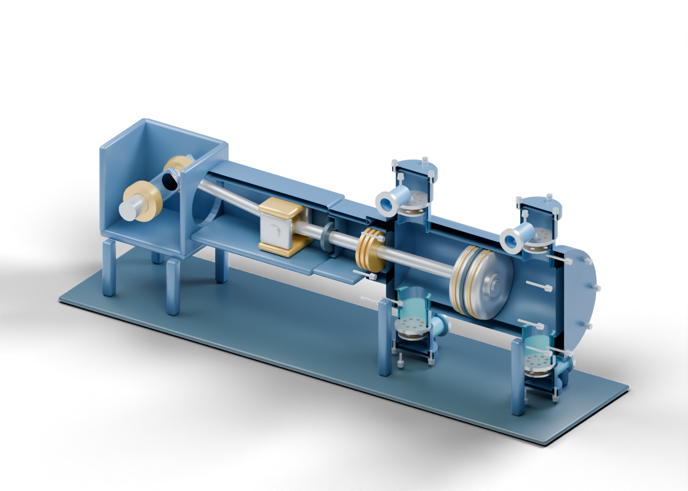
Compressor support frame
Invented support frame. No foundation, structural, vibration or load calculation.
Support leg 1
Illustrative support meeting the enclosure/cylinder region. Attachments and loads are not designed.
Support leg 2
Illustrative support meeting the enclosure/cylinder region. Attachments and loads are not designed.
Support leg 3
Illustrative support meeting the enclosure/cylinder region. Attachments and loads are not designed.
Support leg 4
Illustrative support meeting the enclosure/cylinder region. Attachments and loads are not designed.
Support leg 5
Illustrative support meeting the enclosure/cylinder region. Attachments and loads are not designed.
Support leg 6
Illustrative support meeting the enclosure/cylinder region. Attachments and loads are not designed.
Support leg 7
Illustrative support meeting the enclosure/cylinder region. Attachments and loads are not designed.
Support leg 8
Illustrative support meeting the enclosure/cylinder region. Attachments and loads are not designed.
Crankcase floor
Static enclosure floor. Oil level, pump and lubrication circuit are omitted.
Crankcase top cover
Separate enclosure cover, removed only by presentation controls.
Crankcase end wall
Illustrative frame end wall, without qualified casting or ventilation details.
Crankcase guide wall
Frame wall with an actual opening toward the crosshead guide.
Front crankcase wall
Separate frame wall with a bored crankshaft opening. No pressure or casting specification.
Front main bearing
Separate annular bearing marker around the main journal. No oil-film, load or bearing fit qualification.
Rear crankcase wall
Separate frame wall with a bored crankshaft opening. No pressure or casting specification.
Rear main bearing
Separate annular bearing marker around the main journal. No oil-film, load or bearing fit qualification.
Front main journal
Smooth main journal on the crank axis; no speed, balance or bearing duty.
Rear main journal
Second main journal coaxial with the first. Static geometry only.
Front crank web
Original web marker joining a main journal region to the offset crank pin. No balance or stress qualification.
Rear crank web
Original web marker joining a main journal region to the offset crank pin. No balance or stress qualification.
Offset crank pin
Separate crank-pin axis offset from the main journals. One invented static pose; no cycle or rod-load calculation.
Connecting rod big end
Annular connecting-rod end around the crank pin. Split cap, bolts and qualified bearing fit are omitted.
Connecting rod small end
Annular rod end on the crosshead pin axis. No qualified bearing or force transfer.
Crosshead pin bushing
Separate thin bushing marker between the crosshead pin and rod eye. Clearance is invented.
Connecting rod shank
Original straight shank joining the two rod-eye regions. Its shape and section are teaching choices.
Front crosshead cheek
Crosshead side cheek with a real pin bore. Guide and pin relationships are static.
Rear crosshead cheek
Crosshead side cheek with a real pin bore. Guide and pin relationships are static.
Crosshead pin
Smooth crosshead pin coaxial with the small rod eye. No retention or cyclic load calculation.
Upper crosshead shoe
Separate guide-shoe marker. No wear, running-clearance or side-load qualification.
Upper crosshead guide
Fixed guide surface around the crosshead shoes. No dynamic travel is supplied.
Lower crosshead shoe
Separate guide-shoe marker. No wear, running-clearance or side-load qualification.
Lower crosshead guide
Fixed guide surface around the crosshead shoes. No dynamic travel is supplied.
Front guide wall
Separate side enclosure around the crosshead/rod region.
Rear guide wall
Separate side enclosure around the crosshead/rod region.
Piston rod
Smooth rod from the crosshead region through packing to the piston. No thread form, rod load or dynamic motion.
Front distance-piece wall
Open-ended distance-piece enclosure marker. Purge, ventilation, drains and service requirements are unspecified.
Rear distance-piece wall
Open-ended distance-piece enclosure marker. Purge, ventilation, drains and service requirements are unspecified.
Upper distance-piece wall
Separate distance-piece wall; no qualified gas/oil separation or enclosure classification.
Lower distance-piece wall
Separate distance-piece wall; no qualified gas/oil separation or enclosure classification.
Rod wiper housing
Separate hollow wiper location marker. Drain and sealing details are omitted.
Rod wiper marker
Annular wiper marker around the rod; no lip profile, material or sealing result.
Rod packing housing
Hollow housing around separate rod-packing markers. No packing pressure, cooling or vent plan.
Rod packing ring 1
Separate annular packing marker. Real segmentation, spring loading, leakage and material behaviour are omitted.
Rod packing ring 2
Separate annular packing marker. Real segmentation, spring loading, leakage and material behaviour are omitted.
Rod packing ring 3
Separate annular packing marker. Real segmentation, spring loading, leakage and material behaviour are omitted.
Crank-end head
Cylinder closure around the piston rod, with actual central bore. No pressure rating or qualified packing joint.
Crank-end cylinder flange
Hollow cylinder-end flange with separate drilled fastener bores.
Compression cylinder wall
Actual hollow cylindrical wall with four geometric valve-pocket openings. Invented wall thickness, no gas or pressure simulation.
Head-end cylinder flange
Hollow head-end flange with actual fastener bores. No rated facing or joint.
Head-end head
Solid geometric end closure. No head stress, pressure or manufacturing specification.
Crank-end joint stud 1
Smooth stud marker through an actual geometric bore. Threads and qualified bolt load are omitted.
Crank-end joint washer 1
Separate washer with an open centre. Not a qualified fastener joint.
Crank-end joint nut 1
Bored nut marker. Its circular bore is unthreaded and does not establish retention or torque.
Crank-end joint stud 2
Smooth stud marker through an actual geometric bore. Threads and qualified bolt load are omitted.
Crank-end joint washer 2
Separate washer with an open centre. Not a qualified fastener joint.
Crank-end joint nut 2
Bored nut marker. Its circular bore is unthreaded and does not establish retention or torque.
Crank-end joint stud 3
Smooth stud marker through an actual geometric bore. Threads and qualified bolt load are omitted.
Crank-end joint washer 3
Separate washer with an open centre. Not a qualified fastener joint.
Crank-end joint nut 3
Bored nut marker. Its circular bore is unthreaded and does not establish retention or torque.
Crank-end joint stud 4
Smooth stud marker through an actual geometric bore. Threads and qualified bolt load are omitted.
Crank-end joint washer 4
Separate washer with an open centre. Not a qualified fastener joint.
Crank-end joint nut 4
Bored nut marker. Its circular bore is unthreaded and does not establish retention or torque.
Crank-end joint stud 5
Smooth stud marker through an actual geometric bore. Threads and qualified bolt load are omitted.
Crank-end joint washer 5
Separate washer with an open centre. Not a qualified fastener joint.
Crank-end joint nut 5
Bored nut marker. Its circular bore is unthreaded and does not establish retention or torque.
Crank-end joint stud 6
Smooth stud marker through an actual geometric bore. Threads and qualified bolt load are omitted.
Crank-end joint washer 6
Separate washer with an open centre. Not a qualified fastener joint.
Crank-end joint nut 6
Bored nut marker. Its circular bore is unthreaded and does not establish retention or torque.
Crank-end joint stud 7
Smooth stud marker through an actual geometric bore. Threads and qualified bolt load are omitted.
Crank-end joint washer 7
Separate washer with an open centre. Not a qualified fastener joint.
Crank-end joint nut 7
Bored nut marker. Its circular bore is unthreaded and does not establish retention or torque.
Crank-end joint stud 8
Smooth stud marker through an actual geometric bore. Threads and qualified bolt load are omitted.
Crank-end joint washer 8
Separate washer with an open centre. Not a qualified fastener joint.
Crank-end joint nut 8
Bored nut marker. Its circular bore is unthreaded and does not establish retention or torque.
Head-end joint stud 1
Smooth stud marker through an actual geometric bore. Threads and qualified bolt load are omitted.
Head-end joint washer 1
Separate washer with an open centre. Not a qualified fastener joint.
Head-end joint nut 1
Bored nut marker. Its circular bore is unthreaded and does not establish retention or torque.
Head-end joint stud 2
Smooth stud marker through an actual geometric bore. Threads and qualified bolt load are omitted.
Head-end joint washer 2
Separate washer with an open centre. Not a qualified fastener joint.
Head-end joint nut 2
Bored nut marker. Its circular bore is unthreaded and does not establish retention or torque.
Head-end joint stud 3
Smooth stud marker through an actual geometric bore. Threads and qualified bolt load are omitted.
Head-end joint washer 3
Separate washer with an open centre. Not a qualified fastener joint.
Head-end joint nut 3
Bored nut marker. Its circular bore is unthreaded and does not establish retention or torque.
Head-end joint stud 4
Smooth stud marker through an actual geometric bore. Threads and qualified bolt load are omitted.
Head-end joint washer 4
Separate washer with an open centre. Not a qualified fastener joint.
Head-end joint nut 4
Bored nut marker. Its circular bore is unthreaded and does not establish retention or torque.
Head-end joint stud 5
Smooth stud marker through an actual geometric bore. Threads and qualified bolt load are omitted.
Head-end joint washer 5
Separate washer with an open centre. Not a qualified fastener joint.
Head-end joint nut 5
Bored nut marker. Its circular bore is unthreaded and does not establish retention or torque.
Head-end joint stud 6
Smooth stud marker through an actual geometric bore. Threads and qualified bolt load are omitted.
Head-end joint washer 6
Separate washer with an open centre. Not a qualified fastener joint.
Head-end joint nut 6
Bored nut marker. Its circular bore is unthreaded and does not establish retention or torque.
Head-end joint stud 7
Smooth stud marker through an actual geometric bore. Threads and qualified bolt load are omitted.
Head-end joint washer 7
Separate washer with an open centre. Not a qualified fastener joint.
Head-end joint nut 7
Bored nut marker. Its circular bore is unthreaded and does not establish retention or torque.
Head-end joint stud 8
Smooth stud marker through an actual geometric bore. Threads and qualified bolt load are omitted.
Head-end joint washer 8
Separate washer with an open centre. Not a qualified fastener joint.
Head-end joint nut 8
Bored nut marker. Its circular bore is unthreaded and does not establish retention or torque.
Grooved piston
Original hollow piston marker with two ring recesses and a central rider-band recess. Geometry does not establish a piston material, running clearance or gas performance.
Split piston ring 1
Separate split-ring geometry in a piston recess. Split gap, loading, material and leakage are invented.
Split piston ring 2
Separate split-ring geometry in a piston recess. Split gap, loading, material and leakage are invented.
Piston rider band
Separate closed rider-band marker. Its role differs from the two split-ring markers; no wear or loading result.
Piston retaining marker
Annular retaining marker around the rod. No qualified nut thread, locking or axial retention.
Crank end suction pocket neck
Hollow connection through a drilled cylinder-wall opening toward a separate valve stack. No rated port or simulated flow.
Crank end suction perforated seat
Fixed valve-seat marker with eight actual geometric holes. Not a manufacturer valve or a flow/leakage calculation.
Crank end suction plate marker
Separate annular plate at a fixed illustrated seat relationship. There is no automatic valve event, measured lift, pressure response or leakage result.
Crank end suction guard
Separate bored guard/support marker below the plate in this static concept. Retention and valve lift are unspecified.
Crank end suction spring marker
Original three-turn closed coil marker. Static pose; no valve spring rate, preload, fatigue or event timing.
Crank end suction centre pin
Smooth central guide/attachment marker, without threads or rated valve retention.
Crank end suction outer pocket
Hollow outer pocket above the suction seat or below the discharge seat. Separate boundary necks are illustrative, not a complete manifold.
Crank end suction boundary neck
Hollow boundary connection for the indicated inlet/outlet role. No manifold, support system, gas quantity or process direction simulation.
Crank end suction boundary flange
Open flange marker on the boundary neck; facing, pressure and attachment design omitted.
Crank end suction pocket cover
Separate solid presentation cover on the outer pocket. No qualified pressure or valve-retention joint.
Crank end suction cover flange
Annular pocket-cover flange with actual matching stud bores. No rated facing, preload or pressure-joint qualification.
Crank end suction cover stud 1
Smooth stud marker through an actual geometric bore. Threads and qualified bolt load are omitted.
Crank end suction cover washer 1
Separate washer with an open centre. Not a qualified fastener joint.
Crank end suction cover nut 1
Bored nut marker. Its circular bore is unthreaded and does not establish retention or torque.
Crank end suction cover stud 2
Smooth stud marker through an actual geometric bore. Threads and qualified bolt load are omitted.
Crank end suction cover washer 2
Separate washer with an open centre. Not a qualified fastener joint.
Crank end suction cover nut 2
Bored nut marker. Its circular bore is unthreaded and does not establish retention or torque.
Crank end suction cover stud 3
Smooth stud marker through an actual geometric bore. Threads and qualified bolt load are omitted.
Crank end suction cover washer 3
Separate washer with an open centre. Not a qualified fastener joint.
Crank end suction cover nut 3
Bored nut marker. Its circular bore is unthreaded and does not establish retention or torque.
Crank end suction cover stud 4
Smooth stud marker through an actual geometric bore. Threads and qualified bolt load are omitted.
Crank end suction cover washer 4
Separate washer with an open centre. Not a qualified fastener joint.
Crank end suction cover nut 4
Bored nut marker. Its circular bore is unthreaded and does not establish retention or torque.
Crank end discharge pocket neck
Hollow connection through a drilled cylinder-wall opening toward a separate valve stack. No rated port or simulated flow.
Crank end discharge perforated seat
Fixed valve-seat marker with eight actual geometric holes. Not a manufacturer valve or a flow/leakage calculation.
Crank end discharge plate marker
Separate annular plate at a fixed illustrated seat relationship. There is no automatic valve event, measured lift, pressure response or leakage result.
Crank end discharge guard
Separate bored guard/support marker below the plate in this static concept. Retention and valve lift are unspecified.
Crank end discharge spring marker
Original three-turn closed coil marker. Static pose; no valve spring rate, preload, fatigue or event timing.
Crank end discharge centre pin
Smooth central guide/attachment marker, without threads or rated valve retention.
Crank end discharge outer pocket
Hollow outer pocket above the suction seat or below the discharge seat. Separate boundary necks are illustrative, not a complete manifold.
Crank end discharge boundary neck
Hollow boundary connection for the indicated inlet/outlet role. No manifold, support system, gas quantity or process direction simulation.
Crank end discharge boundary flange
Open flange marker on the boundary neck; facing, pressure and attachment design omitted.
Crank end discharge pocket cover
Separate solid presentation cover on the outer pocket. No qualified pressure or valve-retention joint.
Crank end discharge cover flange
Annular pocket-cover flange with actual matching stud bores. No rated facing, preload or pressure-joint qualification.
Crank end discharge cover stud 1
Smooth stud marker through an actual geometric bore. Threads and qualified bolt load are omitted.
Crank end discharge cover washer 1
Separate washer with an open centre. Not a qualified fastener joint.
Crank end discharge cover nut 1
Bored nut marker. Its circular bore is unthreaded and does not establish retention or torque.
Crank end discharge cover stud 2
Smooth stud marker through an actual geometric bore. Threads and qualified bolt load are omitted.
Crank end discharge cover washer 2
Separate washer with an open centre. Not a qualified fastener joint.
Crank end discharge cover nut 2
Bored nut marker. Its circular bore is unthreaded and does not establish retention or torque.
Crank end discharge cover stud 3
Smooth stud marker through an actual geometric bore. Threads and qualified bolt load are omitted.
Crank end discharge cover washer 3
Separate washer with an open centre. Not a qualified fastener joint.
Crank end discharge cover nut 3
Bored nut marker. Its circular bore is unthreaded and does not establish retention or torque.
Crank end discharge cover stud 4
Smooth stud marker through an actual geometric bore. Threads and qualified bolt load are omitted.
Crank end discharge cover washer 4
Separate washer with an open centre. Not a qualified fastener joint.
Crank end discharge cover nut 4
Bored nut marker. Its circular bore is unthreaded and does not establish retention or torque.
Head end suction pocket neck
Hollow connection through a drilled cylinder-wall opening toward a separate valve stack. No rated port or simulated flow.
Head end suction perforated seat
Fixed valve-seat marker with eight actual geometric holes. Not a manufacturer valve or a flow/leakage calculation.
Head end suction plate marker
Separate annular plate at a fixed illustrated seat relationship. There is no automatic valve event, measured lift, pressure response or leakage result.
Head end suction guard
Separate bored guard/support marker below the plate in this static concept. Retention and valve lift are unspecified.
Head end suction spring marker
Original three-turn closed coil marker. Static pose; no valve spring rate, preload, fatigue or event timing.
Head end suction centre pin
Smooth central guide/attachment marker, without threads or rated valve retention.
Head end suction outer pocket
Hollow outer pocket above the suction seat or below the discharge seat. Separate boundary necks are illustrative, not a complete manifold.
Head end suction boundary neck
Hollow boundary connection for the indicated inlet/outlet role. No manifold, support system, gas quantity or process direction simulation.
Head end suction boundary flange
Open flange marker on the boundary neck; facing, pressure and attachment design omitted.
Head end suction pocket cover
Separate solid presentation cover on the outer pocket. No qualified pressure or valve-retention joint.
Head end suction cover flange
Annular pocket-cover flange with actual matching stud bores. No rated facing, preload or pressure-joint qualification.
Head end suction cover stud 1
Smooth stud marker through an actual geometric bore. Threads and qualified bolt load are omitted.
Head end suction cover washer 1
Separate washer with an open centre. Not a qualified fastener joint.
Head end suction cover nut 1
Bored nut marker. Its circular bore is unthreaded and does not establish retention or torque.
Head end suction cover stud 2
Smooth stud marker through an actual geometric bore. Threads and qualified bolt load are omitted.
Head end suction cover washer 2
Separate washer with an open centre. Not a qualified fastener joint.
Head end suction cover nut 2
Bored nut marker. Its circular bore is unthreaded and does not establish retention or torque.
Head end suction cover stud 3
Smooth stud marker through an actual geometric bore. Threads and qualified bolt load are omitted.
Head end suction cover washer 3
Separate washer with an open centre. Not a qualified fastener joint.
Head end suction cover nut 3
Bored nut marker. Its circular bore is unthreaded and does not establish retention or torque.
Head end suction cover stud 4
Smooth stud marker through an actual geometric bore. Threads and qualified bolt load are omitted.
Head end suction cover washer 4
Separate washer with an open centre. Not a qualified fastener joint.
Head end suction cover nut 4
Bored nut marker. Its circular bore is unthreaded and does not establish retention or torque.
Head end discharge pocket neck
Hollow connection through a drilled cylinder-wall opening toward a separate valve stack. No rated port or simulated flow.
Head end discharge perforated seat
Fixed valve-seat marker with eight actual geometric holes. Not a manufacturer valve or a flow/leakage calculation.
Head end discharge plate marker
Separate annular plate at a fixed illustrated seat relationship. There is no automatic valve event, measured lift, pressure response or leakage result.
Head end discharge guard
Separate bored guard/support marker below the plate in this static concept. Retention and valve lift are unspecified.
Head end discharge spring marker
Original three-turn closed coil marker. Static pose; no valve spring rate, preload, fatigue or event timing.
Head end discharge centre pin
Smooth central guide/attachment marker, without threads or rated valve retention.
Head end discharge outer pocket
Hollow outer pocket above the suction seat or below the discharge seat. Separate boundary necks are illustrative, not a complete manifold.
Head end discharge boundary neck
Hollow boundary connection for the indicated inlet/outlet role. No manifold, support system, gas quantity or process direction simulation.
Head end discharge boundary flange
Open flange marker on the boundary neck; facing, pressure and attachment design omitted.
Head end discharge pocket cover
Separate solid presentation cover on the outer pocket. No qualified pressure or valve-retention joint.
Head end discharge cover flange
Annular pocket-cover flange with actual matching stud bores. No rated facing, preload or pressure-joint qualification.
Head end discharge cover stud 1
Smooth stud marker through an actual geometric bore. Threads and qualified bolt load are omitted.
Head end discharge cover washer 1
Separate washer with an open centre. Not a qualified fastener joint.
Head end discharge cover nut 1
Bored nut marker. Its circular bore is unthreaded and does not establish retention or torque.
Head end discharge cover stud 2
Smooth stud marker through an actual geometric bore. Threads and qualified bolt load are omitted.
Head end discharge cover washer 2
Separate washer with an open centre. Not a qualified fastener joint.
Head end discharge cover nut 2
Bored nut marker. Its circular bore is unthreaded and does not establish retention or torque.
Head end discharge cover stud 3
Smooth stud marker through an actual geometric bore. Threads and qualified bolt load are omitted.
Head end discharge cover washer 3
Separate washer with an open centre. Not a qualified fastener joint.
Head end discharge cover nut 3
Bored nut marker. Its circular bore is unthreaded and does not establish retention or torque.
Head end discharge cover stud 4
Smooth stud marker through an actual geometric bore. Threads and qualified bolt load are omitted.
Head end discharge cover washer 4
Separate washer with an open centre. Not a qualified fastener joint.
Head end discharge cover nut 4
Bored nut marker. Its circular bore is unthreaded and does not establish retention or torque.