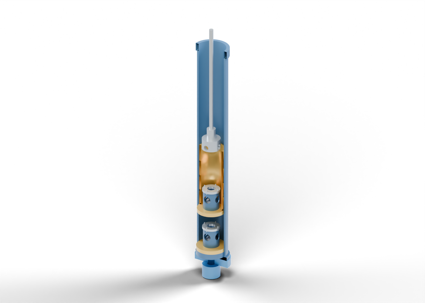
Pump barrel wall
Hollow stationary barrel surrounds the moving plunger. Reveal internals removes this enclosure. Original teaching proportions; no pressure rating, verified fit or material specification.
Barrel lower coupling
Annular lower connection toward the fixed intake assembly. Original teaching proportions; no pressure rating, verified fit or material specification.
Barrel upper coupling
Open upper connection toward production tubing. Tubing, anchor and well geometry are outside this model. Original teaching proportions; no pressure rating, verified fit or material specification.
Seating shoe concept
Lower mounting boundary of an insert-style teaching pump. Retrieval/hold-down details and seating performance are omitted. Original teaching proportions; no pressure rating, verified fit or material specification.
Intake neck
Open geometric passage toward the lower pump intake. Screen, gas anchor and formation boundary are not included. Original teaching proportions; no pressure rating, verified fit or material specification.
Standing valve carrier
Stationary bored carrier below the standing seat. This annulus meets the barrel bore geometrically. Original teaching proportions; no pressure rating, verified fit or material specification.
Standing seat retainer
Annular carrier around a separate standing-valve seat. Joint sealing and retention are unqualified. Original teaching proportions; no pressure rating, verified fit or material specification.
Standing valve seat
Annular seat beneath a ball. The circular edge marks a neutral seated geometry. Original teaching proportions; no pressure rating, verified fit or material specification.
Standing valve ball
Ball in an initial seated teaching pose, with an independent illustrative lift control. This is not a measured valve position, leakage calculation or pressure-responsive simulation.
Standing valve cage
Hollow cage around the ball, with four geometric side windows. Ball motion/contact and flow capacity are not qualified. Original teaching proportions; no pressure rating, verified fit or material specification.
Standing valve cage crown
Annular upper stop concept with an open centre. The stop opening is smaller than the ball diameter. Original teaching proportions; no pressure rating, verified fit or material specification.
Standing valve crown fastener 1
Separate generic fastener position without thread, preload or adjustment instruction.
Standing valve crown fastener 2
Separate generic fastener position without thread, preload or adjustment instruction.
Standing valve crown fastener 3
Separate generic fastener position without thread, preload or adjustment instruction.
Standing valve crown fastener 4
Separate generic fastener position without thread, preload or adjustment instruction.
Travelling seat retainer
Carrier at the lower end of the moving hollow plunger. Original teaching proportions; no pressure rating, verified fit or material specification.
Travelling valve seat
Annular seat beneath a ball. The circular edge marks a neutral seated geometry. Original teaching proportions; no pressure rating, verified fit or material specification.
Travelling valve ball
Ball in an initial seated teaching pose, with an independent illustrative lift control. This is not a measured valve position, leakage calculation or pressure-responsive simulation.
Travelling valve cage
Hollow cage around the ball, with four geometric side windows. Ball motion/contact and flow capacity are not qualified. Original teaching proportions; no pressure rating, verified fit or material specification.
Travelling valve cage crown
Annular upper stop concept with an open centre. The stop opening is smaller than the ball diameter. Original teaching proportions; no pressure rating, verified fit or material specification.
Travelling valve crown fastener 1
Separate generic fastener position without thread, preload or adjustment instruction.
Travelling valve crown fastener 2
Separate generic fastener position without thread, preload or adjustment instruction.
Travelling valve crown fastener 3
Separate generic fastener position without thread, preload or adjustment instruction.
Travelling valve crown fastener 4
Separate generic fastener position without thread, preload or adjustment instruction.
Hollow grooved plunger
One continuous hollow sleeve with three shallow outside grooves. These are teaching features, not separate sleeve segments, a verified clearance design or a wear specification.
Plunger discharge neck
Hollow neck with four side ports connects the plunger bore to space above the plunger. Original teaching proportions; no pressure rating, verified fit or material specification.
Rod adapter closure
Solid top adapter above the side-discharge ports. Threads and load capacity are not specified.
Rod coupling
Annular coupling marker around the drive-rod connection. Mating threads and rod-string specification are omitted. Original teaching proportions; no pressure rating, verified fit or material specification.
Drive rod
Shortened connection toward a sucker-rod string. The complete string, rod stress and the surface drive are outside this model.