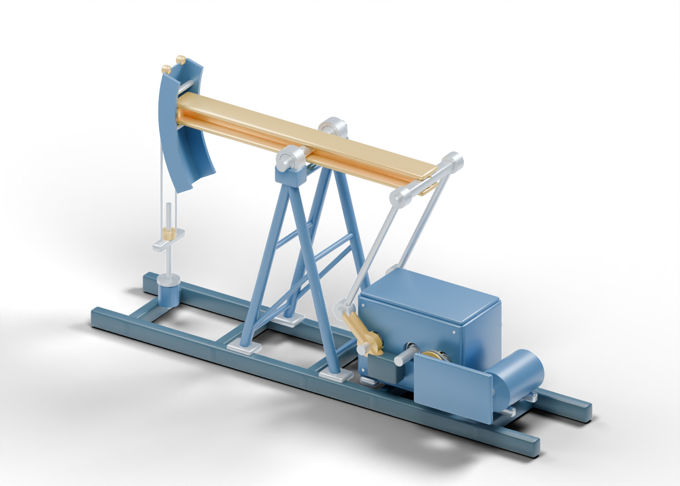
Base rail -0.72
Longitudinal support rail. Invented proportions; not a rated component, manufacturing drawing or operating instruction.
Base rail 0.72
Longitudinal support rail. Invented proportions; not a rated component, manufacturing drawing or operating instruction.
Base crossmember -2.9
Crossmember joins the support rails. Invented proportions; not a rated component, manufacturing drawing or operating instruction.
Base crossmember -1.3
Crossmember joins the support rails. Invented proportions; not a rated component, manufacturing drawing or operating instruction.
Base crossmember 0.4
Crossmember joins the support rails. Invented proportions; not a rated component, manufacturing drawing or operating instruction.
Base crossmember 1.7
Crossmember joins the support rails. Invented proportions; not a rated component, manufacturing drawing or operating instruction.
Base crossmember 3.6
Crossmember joins the support rails. Invented proportions; not a rated component, manufacturing drawing or operating instruction.
Samson leg -0.85 / -0.6
Inclined support carries the central beam-bearing assembly. Invented proportions; not a rated component, manufacturing drawing or operating instruction.
Samson foot -0.85 / -0.6
Separate foot at the structural support base. Invented proportions; not a rated component, manufacturing drawing or operating instruction.
Samson leg 0.85 / -0.6
Inclined support carries the central beam-bearing assembly. Invented proportions; not a rated component, manufacturing drawing or operating instruction.
Samson foot 0.85 / -0.6
Separate foot at the structural support base. Invented proportions; not a rated component, manufacturing drawing or operating instruction.
Samson diagonal -0.6
Diagonal brace meets the two leg centerlines in its support plane. Invented proportions; not a rated component, manufacturing drawing or operating instruction.
Samson leg -0.85 / 0.6
Inclined support carries the central beam-bearing assembly. Invented proportions; not a rated component, manufacturing drawing or operating instruction.
Samson foot -0.85 / 0.6
Separate foot at the structural support base. Invented proportions; not a rated component, manufacturing drawing or operating instruction.
Samson leg 0.85 / 0.6
Inclined support carries the central beam-bearing assembly. Invented proportions; not a rated component, manufacturing drawing or operating instruction.
Samson foot 0.85 / 0.6
Separate foot at the structural support base. Invented proportions; not a rated component, manufacturing drawing or operating instruction.
Samson diagonal 0.6
Diagonal brace meets the two leg centerlines in its support plane. Invented proportions; not a rated component, manufacturing drawing or operating instruction.
Samson cross tie 0.65 / -1
Cross tie meets the leg centerline in both support planes. Invented proportions; not a rated component, manufacturing drawing or operating instruction.
Samson cross tie 0.65 / 1
Cross tie meets the leg centerline in both support planes. Invented proportions; not a rated component, manufacturing drawing or operating instruction.
Samson cross tie 2.15 / -1
Cross tie meets the leg centerline in both support planes. Invented proportions; not a rated component, manufacturing drawing or operating instruction.
Samson cross tie 2.15 / 1
Cross tie meets the leg centerline in both support planes. Invented proportions; not a rated component, manufacturing drawing or operating instruction.
Samson cross tie 3.42 / -1
Cross tie meets the leg centerline in both support planes. Invented proportions; not a rated component, manufacturing drawing or operating instruction.
Samson cross tie 3.42 / 1
Cross tie meets the leg centerline in both support planes. Invented proportions; not a rated component, manufacturing drawing or operating instruction.
Center bearing shaft
Common pivot axis of the walking beam. Invented proportions; not a rated component, manufacturing drawing or operating instruction.
Center bearing pedestal -0.58
Supports the annular beam-bearing concept. Invented proportions; not a rated component, manufacturing drawing or operating instruction.
Center bearing outer race -0.58
Stationary outer race of the central bearing. Invented proportions; not a rated component, manufacturing drawing or operating instruction.
Center bearing inner race -0.58
Inner race surrounding the pivot shaft. Invented proportions; not a rated component, manufacturing drawing or operating instruction.
Center bearing pedestal 0.58
Supports the annular beam-bearing concept. Invented proportions; not a rated component, manufacturing drawing or operating instruction.
Center bearing outer race 0.58
Stationary outer race of the central bearing. Invented proportions; not a rated component, manufacturing drawing or operating instruction.
Center bearing inner race 0.58
Inner race surrounding the pivot shaft. Invented proportions; not a rated component, manufacturing drawing or operating instruction.
Walking beam flange 3.66
Flange of the illustrative I-section walking beam. Invented proportions; not a rated component, manufacturing drawing or operating instruction.
Walking beam flange 3.94
Flange of the illustrative I-section walking beam. Invented proportions; not a rated component, manufacturing drawing or operating instruction.
Walking beam web
Web joins the upper and lower beam flanges. Invented proportions; not a rated component, manufacturing drawing or operating instruction.
Beam stiffener -2.35
Local plate stiffens the schematic beam section. Invented proportions; not a rated component, manufacturing drawing or operating instruction.
Beam stiffener 0
Local plate stiffens the schematic beam section. Invented proportions; not a rated component, manufacturing drawing or operating instruction.
Beam stiffener 2.12
Local plate stiffens the schematic beam section. Invented proportions; not a rated component, manufacturing drawing or operating instruction.
Horsehead cheek -0.32
Curved side plate concentric with the beam pivot in the neutral teaching pose. Invented proportions; not a rated component, manufacturing drawing or operating instruction.
Horsehead cheek 0.32
Curved side plate concentric with the beam pivot in the neutral teaching pose. Invented proportions; not a rated component, manufacturing drawing or operating instruction.
Curved horsehead face
Curved outer surface carries the bridle; radius is a teaching choice. Invented proportions; not a rated component, manufacturing drawing or operating instruction.
Horsehead cross tie 3.5
Cross tie joins the horsehead cheeks. Invented proportions; not a rated component, manufacturing drawing or operating instruction.
Horsehead cross tie 3.8
Cross tie joins the horsehead cheeks. Invented proportions; not a rated component, manufacturing drawing or operating instruction.
Horsehead cross tie 4.1
Cross tie joins the horsehead cheeks. Invented proportions; not a rated component, manufacturing drawing or operating instruction.
Bridle -0.2
Original curved-to-vertical cable concept; no cable construction, load rating or stroke simulation.
Bridle attachment -0.2
Conceptual cable attachment; retention and fatigue are not qualified. Invented proportions; not a rated component, manufacturing drawing or operating instruction.
Bridle 0.2
Original curved-to-vertical cable concept; no cable construction, load rating or stroke simulation.
Bridle attachment 0.2
Conceptual cable attachment; retention and fatigue are not qualified. Invented proportions; not a rated component, manufacturing drawing or operating instruction.
Carrier bar
Connects the two bridle legs toward the polished rod. Invented proportions; not a rated component, manufacturing drawing or operating instruction.
Polished rod clamp
Annular clamp marker above the carrier; bolt loading is omitted. Invented proportions; not a rated component, manufacturing drawing or operating instruction.
Polished rod
Smooth rod continues below the illustrated surface boundary. Extra neutral length keeps it through the packing over the invented geometric cycle; no matched field stroke or downhole rod string is represented. Invented proportions; not a rated component, manufacturing drawing or operating instruction.
Stuffing box body
Hollow schematic housing around polished-rod packing. Invented proportions; not a rated component, manufacturing drawing or operating instruction.
Polished rod packing 1
Separate packing-ring concept around the smooth rod. Invented proportions; not a rated component, manufacturing drawing or operating instruction.
Polished rod packing 2
Separate packing-ring concept around the smooth rod. Invented proportions; not a rated component, manufacturing drawing or operating instruction.
Polished rod packing 3
Separate packing-ring concept around the smooth rod. Invented proportions; not a rated component, manufacturing drawing or operating instruction.
Stuffing box follower
Follower above the packing stack. Adjustment and sealing performance are not represented. Invented proportions; not a rated component, manufacturing drawing or operating instruction.
Stuffing box gland
Annular upper gland marker. Invented proportions; not a rated component, manufacturing drawing or operating instruction.
First stage pinion
Separate spur-gear teaching silhouette. Tooth flanks are trapezoidal markers, not involute manufacturing profiles. Invented proportions; not a rated component, manufacturing drawing or operating instruction.
First stage wheel
Separate spur-gear teaching silhouette. Tooth flanks are trapezoidal markers, not involute manufacturing profiles. Invented proportions; not a rated component, manufacturing drawing or operating instruction.
Second stage pinion
Separate spur-gear teaching silhouette. Tooth flanks are trapezoidal markers, not involute manufacturing profiles. Invented proportions; not a rated component, manufacturing drawing or operating instruction.
Second stage wheel
Separate spur-gear teaching silhouette. Tooth flanks are trapezoidal markers, not involute manufacturing profiles. Invented proportions; not a rated component, manufacturing drawing or operating instruction.
Input reducer shaft
Shaft shared by its gear and bearing concepts. Invented proportions; not a rated component, manufacturing drawing or operating instruction.
Input bearing outer -0.44
Stationary annular bearing race. Invented proportions; not a rated component, manufacturing drawing or operating instruction.
Input bearing inner -0.44
Annular shaft-side bearing race. Invented proportions; not a rated component, manufacturing drawing or operating instruction.
Input bearing element -0.44 / 1
Separate static rolling-element marker; cage, lubrication and loaded contacts are omitted.
Input bearing element -0.44 / 2
Separate static rolling-element marker; cage, lubrication and loaded contacts are omitted.
Input bearing element -0.44 / 3
Separate static rolling-element marker; cage, lubrication and loaded contacts are omitted.
Input bearing element -0.44 / 4
Separate static rolling-element marker; cage, lubrication and loaded contacts are omitted.
Input bearing element -0.44 / 5
Separate static rolling-element marker; cage, lubrication and loaded contacts are omitted.
Input bearing element -0.44 / 6
Separate static rolling-element marker; cage, lubrication and loaded contacts are omitted.
Input bearing element -0.44 / 7
Separate static rolling-element marker; cage, lubrication and loaded contacts are omitted.
Input bearing element -0.44 / 8
Separate static rolling-element marker; cage, lubrication and loaded contacts are omitted.
Input bearing outer 0.44
Stationary annular bearing race. Invented proportions; not a rated component, manufacturing drawing or operating instruction.
Input bearing inner 0.44
Annular shaft-side bearing race. Invented proportions; not a rated component, manufacturing drawing or operating instruction.
Input bearing element 0.44 / 1
Separate static rolling-element marker; cage, lubrication and loaded contacts are omitted.
Input bearing element 0.44 / 2
Separate static rolling-element marker; cage, lubrication and loaded contacts are omitted.
Input bearing element 0.44 / 3
Separate static rolling-element marker; cage, lubrication and loaded contacts are omitted.
Input bearing element 0.44 / 4
Separate static rolling-element marker; cage, lubrication and loaded contacts are omitted.
Input bearing element 0.44 / 5
Separate static rolling-element marker; cage, lubrication and loaded contacts are omitted.
Input bearing element 0.44 / 6
Separate static rolling-element marker; cage, lubrication and loaded contacts are omitted.
Input bearing element 0.44 / 7
Separate static rolling-element marker; cage, lubrication and loaded contacts are omitted.
Input bearing element 0.44 / 8
Separate static rolling-element marker; cage, lubrication and loaded contacts are omitted.
Intermediate reducer shaft
Shaft shared by its gear and bearing concepts. Invented proportions; not a rated component, manufacturing drawing or operating instruction.
Intermediate bearing outer -0.44
Stationary annular bearing race. Invented proportions; not a rated component, manufacturing drawing or operating instruction.
Intermediate bearing inner -0.44
Annular shaft-side bearing race. Invented proportions; not a rated component, manufacturing drawing or operating instruction.
Intermediate bearing element -0.44 / 1
Separate static rolling-element marker; cage, lubrication and loaded contacts are omitted.
Intermediate bearing element -0.44 / 2
Separate static rolling-element marker; cage, lubrication and loaded contacts are omitted.
Intermediate bearing element -0.44 / 3
Separate static rolling-element marker; cage, lubrication and loaded contacts are omitted.
Intermediate bearing element -0.44 / 4
Separate static rolling-element marker; cage, lubrication and loaded contacts are omitted.
Intermediate bearing element -0.44 / 5
Separate static rolling-element marker; cage, lubrication and loaded contacts are omitted.
Intermediate bearing element -0.44 / 6
Separate static rolling-element marker; cage, lubrication and loaded contacts are omitted.
Intermediate bearing element -0.44 / 7
Separate static rolling-element marker; cage, lubrication and loaded contacts are omitted.
Intermediate bearing element -0.44 / 8
Separate static rolling-element marker; cage, lubrication and loaded contacts are omitted.
Intermediate bearing outer 0.44
Stationary annular bearing race. Invented proportions; not a rated component, manufacturing drawing or operating instruction.
Intermediate bearing inner 0.44
Annular shaft-side bearing race. Invented proportions; not a rated component, manufacturing drawing or operating instruction.
Intermediate bearing element 0.44 / 1
Separate static rolling-element marker; cage, lubrication and loaded contacts are omitted.
Intermediate bearing element 0.44 / 2
Separate static rolling-element marker; cage, lubrication and loaded contacts are omitted.
Intermediate bearing element 0.44 / 3
Separate static rolling-element marker; cage, lubrication and loaded contacts are omitted.
Intermediate bearing element 0.44 / 4
Separate static rolling-element marker; cage, lubrication and loaded contacts are omitted.
Intermediate bearing element 0.44 / 5
Separate static rolling-element marker; cage, lubrication and loaded contacts are omitted.
Intermediate bearing element 0.44 / 6
Separate static rolling-element marker; cage, lubrication and loaded contacts are omitted.
Intermediate bearing element 0.44 / 7
Separate static rolling-element marker; cage, lubrication and loaded contacts are omitted.
Intermediate bearing element 0.44 / 8
Separate static rolling-element marker; cage, lubrication and loaded contacts are omitted.
Output reducer shaft
Shaft shared by its gear and bearing concepts. Invented proportions; not a rated component, manufacturing drawing or operating instruction.
Output bearing outer -0.44
Stationary annular bearing race. Invented proportions; not a rated component, manufacturing drawing or operating instruction.
Output bearing inner -0.44
Annular shaft-side bearing race. Invented proportions; not a rated component, manufacturing drawing or operating instruction.
Output bearing element -0.44 / 1
Separate static rolling-element marker; cage, lubrication and loaded contacts are omitted.
Output bearing element -0.44 / 2
Separate static rolling-element marker; cage, lubrication and loaded contacts are omitted.
Output bearing element -0.44 / 3
Separate static rolling-element marker; cage, lubrication and loaded contacts are omitted.
Output bearing element -0.44 / 4
Separate static rolling-element marker; cage, lubrication and loaded contacts are omitted.
Output bearing element -0.44 / 5
Separate static rolling-element marker; cage, lubrication and loaded contacts are omitted.
Output bearing element -0.44 / 6
Separate static rolling-element marker; cage, lubrication and loaded contacts are omitted.
Output bearing element -0.44 / 7
Separate static rolling-element marker; cage, lubrication and loaded contacts are omitted.
Output bearing element -0.44 / 8
Separate static rolling-element marker; cage, lubrication and loaded contacts are omitted.
Output bearing outer 0.44
Stationary annular bearing race. Invented proportions; not a rated component, manufacturing drawing or operating instruction.
Output bearing inner 0.44
Annular shaft-side bearing race. Invented proportions; not a rated component, manufacturing drawing or operating instruction.
Output bearing element 0.44 / 1
Separate static rolling-element marker; cage, lubrication and loaded contacts are omitted.
Output bearing element 0.44 / 2
Separate static rolling-element marker; cage, lubrication and loaded contacts are omitted.
Output bearing element 0.44 / 3
Separate static rolling-element marker; cage, lubrication and loaded contacts are omitted.
Output bearing element 0.44 / 4
Separate static rolling-element marker; cage, lubrication and loaded contacts are omitted.
Output bearing element 0.44 / 5
Separate static rolling-element marker; cage, lubrication and loaded contacts are omitted.
Output bearing element 0.44 / 6
Separate static rolling-element marker; cage, lubrication and loaded contacts are omitted.
Output bearing element 0.44 / 7
Separate static rolling-element marker; cage, lubrication and loaded contacts are omitted.
Output bearing element 0.44 / 8
Separate static rolling-element marker; cage, lubrication and loaded contacts are omitted.
Reducer side cover -0.53
Removable teaching side plate with aligned shaft bores. Invented proportions; not a rated component, manufacturing drawing or operating instruction.
Reducer cover fastener 1.34 / -0.53 / 0.57
Separate generic fastener marker; no thread, preload or torque specification.
Reducer cover fastener 1.34 / -0.53 / 1.68
Separate generic fastener marker; no thread, preload or torque specification.
Reducer cover fastener 3.02 / -0.53 / 0.57
Separate generic fastener marker; no thread, preload or torque specification.
Reducer cover fastener 3.02 / -0.53 / 1.68
Separate generic fastener marker; no thread, preload or torque specification.
Reducer side cover 0.53
Removable teaching side plate with aligned shaft bores. Invented proportions; not a rated component, manufacturing drawing or operating instruction.
Reducer cover fastener 1.34 / 0.53 / 0.57
Separate generic fastener marker; no thread, preload or torque specification.
Reducer cover fastener 1.34 / 0.53 / 1.68
Separate generic fastener marker; no thread, preload or torque specification.
Reducer cover fastener 3.02 / 0.53 / 0.57
Separate generic fastener marker; no thread, preload or torque specification.
Reducer cover fastener 3.02 / 0.53 / 1.68
Separate generic fastener marker; no thread, preload or torque specification.
Reducer horizontal wall 0.43
Hollow enclosure wall around the gear planes. Invented proportions; not a rated component, manufacturing drawing or operating instruction.
Reducer horizontal wall 1.82
Hollow enclosure wall around the gear planes. Invented proportions; not a rated component, manufacturing drawing or operating instruction.
Reducer end wall 1.23
Hollow enclosure end wall. Invented proportions; not a rated component, manufacturing drawing or operating instruction.
Reducer end wall 3.13
Hollow enclosure end wall. Invented proportions; not a rated component, manufacturing drawing or operating instruction.
Reducer foot 1.42
Separate support foot of the reducer housing. Invented proportions; not a rated component, manufacturing drawing or operating instruction.
Reducer foot 2.92
Separate support foot of the reducer housing. Invented proportions; not a rated component, manufacturing drawing or operating instruction.
Motor enclosure
Generic electric prime-mover enclosure; winding, electrical supply and controls are omitted. Invented proportions; not a rated component, manufacturing drawing or operating instruction.
Motor output shaft
Connects the motor-side pulley to the generic prime mover. Invented proportions; not a rated component, manufacturing drawing or operating instruction.
Motor foot -0.37
Separate motor support foot. Invented proportions; not a rated component, manufacturing drawing or operating instruction.
Motor foot 0.23
Separate motor support foot. Invented proportions; not a rated component, manufacturing drawing or operating instruction.
Motor pulley
Small annular motor-side pulley. Invented proportions; not a rated component, manufacturing drawing or operating instruction.
Reducer input pulley
Larger annular input pulley. Invented proportions; not a rated component, manufacturing drawing or operating instruction.
Belt tangent 1
Straight span tangent to the two illustrative pitch circles. Belt pitch, tension and transmission power are not qualified. Invented proportions; not a rated component, manufacturing drawing or operating instruction.
Belt tangent 2
Straight span tangent to the two illustrative pitch circles. Belt pitch, tension and transmission power are not qualified. Invented proportions; not a rated component, manufacturing drawing or operating instruction.
Motor belt wrap
Full-wrap belt marker; wrap-contact detail and belt construction are schematic.
Reducer belt wrap
Full-wrap belt marker; wrap-contact detail and belt construction are schematic.
Belt guard
Teaching guard panel hides the belt drive. It is not a complete or qualified machine guarding system. Invented proportions; not a rated component, manufacturing drawing or operating instruction.
Equalizer pivot shaft
Common upper linkage axis at the rear of the walking beam. Invented proportions; not a rated component, manufacturing drawing or operating instruction.
Equalizer crossmember
Joins the paired pitman connection planes. Invented proportions; not a rated component, manufacturing drawing or operating instruction.
Crank arm -0.72
Connects output-shaft axis to the crank-pin axis. Invented proportions; not a rated component, manufacturing drawing or operating instruction.
Crank hub -0.72
Annular hub around the reducer output shaft. Invented proportions; not a rated component, manufacturing drawing or operating instruction.
Counterweight arm -0.72
Extends opposite the pitman crank pin. Invented proportions; not a rated component, manufacturing drawing or operating instruction.
Crank counterweight -0.72
Separate crank-balanced mass concept; no balancing calculation. Invented proportions; not a rated component, manufacturing drawing or operating instruction.
Crank pin -0.72
Common axis shared by crank arm and pitman lower bearing. Invented proportions; not a rated component, manufacturing drawing or operating instruction.
Pitman lower bearing -0.72
Annular lower linkage eye around the crank pin. Invented proportions; not a rated component, manufacturing drawing or operating instruction.
Pitman link -0.72
Rigid link between the lower crank-pin and upper equalizer axes. Invented proportions; not a rated component, manufacturing drawing or operating instruction.
Pitman upper bearing -0.72
Annular upper linkage eye around the equalizer shaft. Invented proportions; not a rated component, manufacturing drawing or operating instruction.
Crank arm 0.72
Connects output-shaft axis to the crank-pin axis. Invented proportions; not a rated component, manufacturing drawing or operating instruction.
Crank hub 0.72
Annular hub around the reducer output shaft. Invented proportions; not a rated component, manufacturing drawing or operating instruction.
Counterweight arm 0.72
Extends opposite the pitman crank pin. Invented proportions; not a rated component, manufacturing drawing or operating instruction.
Crank counterweight 0.72
Separate crank-balanced mass concept; no balancing calculation. Invented proportions; not a rated component, manufacturing drawing or operating instruction.
Crank pin 0.72
Common axis shared by crank arm and pitman lower bearing. Invented proportions; not a rated component, manufacturing drawing or operating instruction.
Pitman lower bearing 0.72
Annular lower linkage eye around the crank pin. Invented proportions; not a rated component, manufacturing drawing or operating instruction.
Pitman link 0.72
Rigid link between the lower crank-pin and upper equalizer axes. Invented proportions; not a rated component, manufacturing drawing or operating instruction.
Pitman upper bearing 0.72
Annular upper linkage eye around the equalizer shaft. Invented proportions; not a rated component, manufacturing drawing or operating instruction.