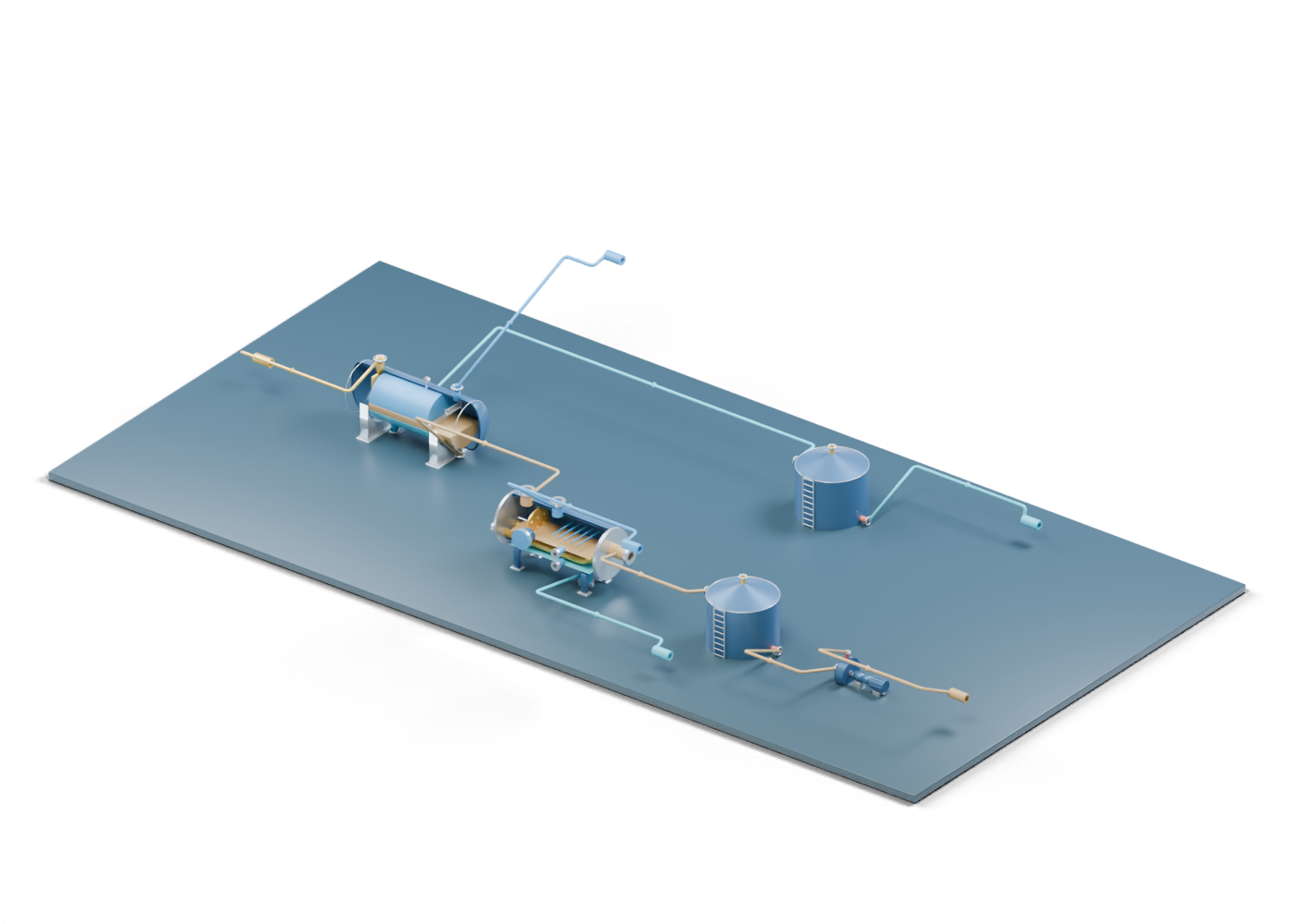
Base frame
Illustrative support frame; foundations and structural design vary.
Three-phase separator / Base frame
Illustrative support frame; foundations and structural design vary. Reused at an invented scale and location; no matching, selection or qualification is implied.
Three-phase separator / Circumferential seam 1
Illustrates a shell-to-head seam location, without weld detail. Reused at an invented scale and location; no matching, selection or qualification is implied.
Three-phase separator / Circumferential seam -1
Illustrates a shell-to-head seam location, without weld detail. Reused at an invented scale and location; no matching, selection or qualification is implied.
Three-phase separator / Demister frame 0.48
Supports a conceptual mist-removal pack. Reused at an invented scale and location; no matching, selection or qualification is implied.
Three-phase separator / Demister frame -0.48
Supports a conceptual mist-removal pack. Reused at an invented scale and location; no matching, selection or qualification is implied.
Three-phase separator / Dished head 1
Generic double-surface dished closure. Shape and thickness are illustrative, with no code qualification. Reused at an invented scale and location; no matching, selection or qualification is implied.
Three-phase separator / Dished head -1
Generic double-surface dished closure. Shape and thickness are illustrative, with no code qualification. Reused at an invented scale and location; no matching, selection or qualification is implied.
Three-phase separator / Feed nozzle
Hollow generic connection with illustrative wall thickness. Welds, facing and pressure ratings are not specified. Reused at an invented scale and location; no matching, selection or qualification is implied.
Three-phase separator / Feed nozzle fastener 1
Generic fastener position. Quantity and size do not specify a rated connection. Reused at an invented scale and location; no matching, selection or qualification is implied.
Three-phase separator / Feed nozzle fastener 2
Generic fastener position. Quantity and size do not specify a rated connection. Reused at an invented scale and location; no matching, selection or qualification is implied.
Three-phase separator / Feed nozzle fastener 3
Generic fastener position. Quantity and size do not specify a rated connection. Reused at an invented scale and location; no matching, selection or qualification is implied.
Three-phase separator / Feed nozzle fastener 4
Generic fastener position. Quantity and size do not specify a rated connection. Reused at an invented scale and location; no matching, selection or qualification is implied.
Three-phase separator / Feed nozzle fastener 5
Generic fastener position. Quantity and size do not specify a rated connection. Reused at an invented scale and location; no matching, selection or qualification is implied.
Three-phase separator / Feed nozzle fastener 6
Generic fastener position. Quantity and size do not specify a rated connection. Reused at an invented scale and location; no matching, selection or qualification is implied.
Three-phase separator / Feed nozzle fastener 7
Generic fastener position. Quantity and size do not specify a rated connection. Reused at an invented scale and location; no matching, selection or qualification is implied.
Three-phase separator / Feed nozzle fastener 8
Generic fastener position. Quantity and size do not specify a rated connection. Reused at an invented scale and location; no matching, selection or qualification is implied.
Three-phase separator / Feed nozzle flange
Illustrative flange ring, with no rated facing or bolt specification. Reused at an invented scale and location; no matching, selection or qualification is implied.
Three-phase separator / Gas outlet
Hollow generic connection with illustrative wall thickness. Welds, facing and pressure ratings are not specified. Reused at an invented scale and location; no matching, selection or qualification is implied.
Three-phase separator / Gas outlet fastener 1
Generic fastener position. Quantity and size do not specify a rated connection. Reused at an invented scale and location; no matching, selection or qualification is implied.
Three-phase separator / Gas outlet fastener 2
Generic fastener position. Quantity and size do not specify a rated connection. Reused at an invented scale and location; no matching, selection or qualification is implied.
Three-phase separator / Gas outlet fastener 3
Generic fastener position. Quantity and size do not specify a rated connection. Reused at an invented scale and location; no matching, selection or qualification is implied.
Three-phase separator / Gas outlet fastener 4
Generic fastener position. Quantity and size do not specify a rated connection. Reused at an invented scale and location; no matching, selection or qualification is implied.
Three-phase separator / Gas outlet fastener 5
Generic fastener position. Quantity and size do not specify a rated connection. Reused at an invented scale and location; no matching, selection or qualification is implied.
Three-phase separator / Gas outlet fastener 6
Generic fastener position. Quantity and size do not specify a rated connection. Reused at an invented scale and location; no matching, selection or qualification is implied.
Three-phase separator / Gas outlet fastener 7
Generic fastener position. Quantity and size do not specify a rated connection. Reused at an invented scale and location; no matching, selection or qualification is implied.
Three-phase separator / Gas outlet fastener 8
Generic fastener position. Quantity and size do not specify a rated connection. Reused at an invented scale and location; no matching, selection or qualification is implied.
Three-phase separator / Gas outlet flange
Illustrative flange ring, with no rated facing or bolt specification. Reused at an invented scale and location; no matching, selection or qualification is implied.
Three-phase separator / Gas space
Illustrative phase volume following the vessel cross-section. Interfaces are static teaching positions, not measured levels or a flow simulation. Reused at an invented scale and location; no matching, selection or qualification is implied.
Three-phase separator / Inlet diverter
Redirects incoming flow toward the separation zone; this plate is a conceptual arrangement. Reused at an invented scale and location; no matching, selection or qualification is implied.
Three-phase separator / Liquid weir
Conceptual overflow weir separates the upstream settling zone from an oil collection compartment. Real arrangements vary. Reused at an invented scale and location; no matching, selection or qualification is implied.
Three-phase separator / Mist vane 0 segment 0
Zigzag teaching representation of a vane pack that helps collect entrained droplets. Performance and production geometry are not reproduced. Reused at an invented scale and location; no matching, selection or qualification is implied.
Three-phase separator / Mist vane 0 segment 1
Zigzag teaching representation of a vane pack that helps collect entrained droplets. Performance and production geometry are not reproduced. Reused at an invented scale and location; no matching, selection or qualification is implied.
Three-phase separator / Mist vane 0 segment 2
Zigzag teaching representation of a vane pack that helps collect entrained droplets. Performance and production geometry are not reproduced. Reused at an invented scale and location; no matching, selection or qualification is implied.
Three-phase separator / Mist vane 1 segment 0
Zigzag teaching representation of a vane pack that helps collect entrained droplets. Performance and production geometry are not reproduced. Reused at an invented scale and location; no matching, selection or qualification is implied.
Three-phase separator / Mist vane 1 segment 1
Zigzag teaching representation of a vane pack that helps collect entrained droplets. Performance and production geometry are not reproduced. Reused at an invented scale and location; no matching, selection or qualification is implied.
Three-phase separator / Mist vane 1 segment 2
Zigzag teaching representation of a vane pack that helps collect entrained droplets. Performance and production geometry are not reproduced. Reused at an invented scale and location; no matching, selection or qualification is implied.
Three-phase separator / Mist vane 2 segment 0
Zigzag teaching representation of a vane pack that helps collect entrained droplets. Performance and production geometry are not reproduced. Reused at an invented scale and location; no matching, selection or qualification is implied.
Three-phase separator / Mist vane 2 segment 1
Zigzag teaching representation of a vane pack that helps collect entrained droplets. Performance and production geometry are not reproduced. Reused at an invented scale and location; no matching, selection or qualification is implied.
Three-phase separator / Mist vane 2 segment 2
Zigzag teaching representation of a vane pack that helps collect entrained droplets. Performance and production geometry are not reproduced. Reused at an invented scale and location; no matching, selection or qualification is implied.
Three-phase separator / Mist vane 3 segment 0
Zigzag teaching representation of a vane pack that helps collect entrained droplets. Performance and production geometry are not reproduced. Reused at an invented scale and location; no matching, selection or qualification is implied.
Three-phase separator / Mist vane 3 segment 1
Zigzag teaching representation of a vane pack that helps collect entrained droplets. Performance and production geometry are not reproduced. Reused at an invented scale and location; no matching, selection or qualification is implied.
Three-phase separator / Mist vane 3 segment 2
Zigzag teaching representation of a vane pack that helps collect entrained droplets. Performance and production geometry are not reproduced. Reused at an invented scale and location; no matching, selection or qualification is implied.
Three-phase separator / Mist vane 4 segment 0
Zigzag teaching representation of a vane pack that helps collect entrained droplets. Performance and production geometry are not reproduced. Reused at an invented scale and location; no matching, selection or qualification is implied.
Three-phase separator / Mist vane 4 segment 1
Zigzag teaching representation of a vane pack that helps collect entrained droplets. Performance and production geometry are not reproduced. Reused at an invented scale and location; no matching, selection or qualification is implied.
Three-phase separator / Mist vane 4 segment 2
Zigzag teaching representation of a vane pack that helps collect entrained droplets. Performance and production geometry are not reproduced. Reused at an invented scale and location; no matching, selection or qualification is implied.
Three-phase separator / Mist vane 5 segment 0
Zigzag teaching representation of a vane pack that helps collect entrained droplets. Performance and production geometry are not reproduced. Reused at an invented scale and location; no matching, selection or qualification is implied.
Three-phase separator / Mist vane 5 segment 1
Zigzag teaching representation of a vane pack that helps collect entrained droplets. Performance and production geometry are not reproduced. Reused at an invented scale and location; no matching, selection or qualification is implied.
Three-phase separator / Mist vane 5 segment 2
Zigzag teaching representation of a vane pack that helps collect entrained droplets. Performance and production geometry are not reproduced. Reused at an invented scale and location; no matching, selection or qualification is implied.
Three-phase separator / Mist vane 6 segment 0
Zigzag teaching representation of a vane pack that helps collect entrained droplets. Performance and production geometry are not reproduced. Reused at an invented scale and location; no matching, selection or qualification is implied.
Three-phase separator / Mist vane 6 segment 1
Zigzag teaching representation of a vane pack that helps collect entrained droplets. Performance and production geometry are not reproduced. Reused at an invented scale and location; no matching, selection or qualification is implied.
Three-phase separator / Mist vane 6 segment 2
Zigzag teaching representation of a vane pack that helps collect entrained droplets. Performance and production geometry are not reproduced. Reused at an invented scale and location; no matching, selection or qualification is implied.
Three-phase separator / Mist vane 7 segment 0
Zigzag teaching representation of a vane pack that helps collect entrained droplets. Performance and production geometry are not reproduced. Reused at an invented scale and location; no matching, selection or qualification is implied.
Three-phase separator / Mist vane 7 segment 1
Zigzag teaching representation of a vane pack that helps collect entrained droplets. Performance and production geometry are not reproduced. Reused at an invented scale and location; no matching, selection or qualification is implied.
Three-phase separator / Mist vane 7 segment 2
Zigzag teaching representation of a vane pack that helps collect entrained droplets. Performance and production geometry are not reproduced. Reused at an invented scale and location; no matching, selection or qualification is implied.
Three-phase separator / Mist vane 8 segment 0
Zigzag teaching representation of a vane pack that helps collect entrained droplets. Performance and production geometry are not reproduced. Reused at an invented scale and location; no matching, selection or qualification is implied.
Three-phase separator / Mist vane 8 segment 1
Zigzag teaching representation of a vane pack that helps collect entrained droplets. Performance and production geometry are not reproduced. Reused at an invented scale and location; no matching, selection or qualification is implied.
Three-phase separator / Mist vane 8 segment 2
Zigzag teaching representation of a vane pack that helps collect entrained droplets. Performance and production geometry are not reproduced. Reused at an invented scale and location; no matching, selection or qualification is implied.
Three-phase separator / Oil collection compartment
Illustrates oil collected beyond the weir; no operating level is specified. Reused at an invented scale and location; no matching, selection or qualification is implied.
Three-phase separator / Oil outlet
Hollow generic connection with illustrative wall thickness. Welds, facing and pressure ratings are not specified. Reused at an invented scale and location; no matching, selection or qualification is implied.
Three-phase separator / Oil outlet fastener 1
Generic fastener position. Quantity and size do not specify a rated connection. Reused at an invented scale and location; no matching, selection or qualification is implied.
Three-phase separator / Oil outlet fastener 2
Generic fastener position. Quantity and size do not specify a rated connection. Reused at an invented scale and location; no matching, selection or qualification is implied.
Three-phase separator / Oil outlet fastener 3
Generic fastener position. Quantity and size do not specify a rated connection. Reused at an invented scale and location; no matching, selection or qualification is implied.
Three-phase separator / Oil outlet fastener 4
Generic fastener position. Quantity and size do not specify a rated connection. Reused at an invented scale and location; no matching, selection or qualification is implied.
Three-phase separator / Oil outlet fastener 5
Generic fastener position. Quantity and size do not specify a rated connection. Reused at an invented scale and location; no matching, selection or qualification is implied.
Three-phase separator / Oil outlet fastener 6
Generic fastener position. Quantity and size do not specify a rated connection. Reused at an invented scale and location; no matching, selection or qualification is implied.
Three-phase separator / Oil outlet fastener 7
Generic fastener position. Quantity and size do not specify a rated connection. Reused at an invented scale and location; no matching, selection or qualification is implied.
Three-phase separator / Oil outlet fastener 8
Generic fastener position. Quantity and size do not specify a rated connection. Reused at an invented scale and location; no matching, selection or qualification is implied.
Three-phase separator / Oil outlet flange
Illustrative flange ring, with no rated facing or bolt specification. Reused at an invented scale and location; no matching, selection or qualification is implied.
Three-phase separator / Oil outlet vortex breaker
A schematic plate over a liquid draw-off; real vortex-breaker design and clearance depend on duty. Reused at an invented scale and location; no matching, selection or qualification is implied.
Three-phase separator / Oil region
Illustrative phase volume following the vessel cross-section. Interfaces are static teaching positions, not measured levels or a flow simulation. Reused at an invented scale and location; no matching, selection or qualification is implied.
Three-phase separator / Pressure indicator
Illustrative gauge location with no numerical reading. Reused at an invented scale and location; no matching, selection or qualification is implied.
Three-phase separator / Pressure instrument connection
Hollow conceptual instrument tapping through the vessel wall; no measurement, calibration or control loop is provided. Reused at an invented scale and location; no matching, selection or qualification is implied.
Three-phase separator / Saddle foot 1.6
Illustrative attachment to a support frame. Reused at an invented scale and location; no matching, selection or qualification is implied.
Three-phase separator / Saddle foot -1.6
Illustrative attachment to a support frame. Reused at an invented scale and location; no matching, selection or qualification is implied.
Three-phase separator / Saddle support 1.6
Curved saddle supports the cylindrical wall; structural design is not specified. Reused at an invented scale and location; no matching, selection or qualification is implied.
Three-phase separator / Saddle support -1.6
Curved saddle supports the cylindrical wall; structural design is not specified. Reused at an invented scale and location; no matching, selection or qualification is implied.
Three-phase separator / Vessel shell
Hollow cylindrical enclosure with five geometric connection openings. Wall thickness, proportions and junctions are illustrative; no reinforcement, weld or pressure qualification. Reused at an invented scale and location; no matching, selection or qualification is implied.
Three-phase separator / Water outlet
Hollow generic connection with illustrative wall thickness. Welds, facing and pressure ratings are not specified. Reused at an invented scale and location; no matching, selection or qualification is implied.
Three-phase separator / Water outlet fastener 1
Generic fastener position. Quantity and size do not specify a rated connection. Reused at an invented scale and location; no matching, selection or qualification is implied.
Three-phase separator / Water outlet fastener 2
Generic fastener position. Quantity and size do not specify a rated connection. Reused at an invented scale and location; no matching, selection or qualification is implied.
Three-phase separator / Water outlet fastener 3
Generic fastener position. Quantity and size do not specify a rated connection. Reused at an invented scale and location; no matching, selection or qualification is implied.
Three-phase separator / Water outlet fastener 4
Generic fastener position. Quantity and size do not specify a rated connection. Reused at an invented scale and location; no matching, selection or qualification is implied.
Three-phase separator / Water outlet fastener 5
Generic fastener position. Quantity and size do not specify a rated connection. Reused at an invented scale and location; no matching, selection or qualification is implied.
Three-phase separator / Water outlet fastener 6
Generic fastener position. Quantity and size do not specify a rated connection. Reused at an invented scale and location; no matching, selection or qualification is implied.
Three-phase separator / Water outlet fastener 7
Generic fastener position. Quantity and size do not specify a rated connection. Reused at an invented scale and location; no matching, selection or qualification is implied.
Three-phase separator / Water outlet fastener 8
Generic fastener position. Quantity and size do not specify a rated connection. Reused at an invented scale and location; no matching, selection or qualification is implied.
Three-phase separator / Water outlet flange
Illustrative flange ring, with no rated facing or bolt specification. Reused at an invented scale and location; no matching, selection or qualification is implied.
Three-phase separator / Water outlet vortex breaker
A schematic plate over a liquid draw-off; real vortex-breaker design and clearance depend on duty. Reused at an invented scale and location; no matching, selection or qualification is implied.
Three-phase separator / Water region
Illustrative phase volume following the vessel cross-section. Interfaces are static teaching positions, not measured levels or a flow simulation. Reused at an invented scale and location; no matching, selection or qualification is implied.
Heater treater / Closed heater-treater inspection cover
Separate static closed cover, no maintenance procedure. Invented static role geometry. No selected emulsion, heat duty, fire, fuel, draft, burner management, pressure, temperature, controls, liquid level, separation result or safe service. Reused at an invented scale and location; no matching, selection or qualification is implied.
Heater treater / Closed heater-treater inspection neck
Side opening with separate closed cover; no vessel-entry guidance. Invented static role geometry. No selected emulsion, heat duty, fire, fuel, draft, burner management, pressure, temperature, controls, liquid level, separation result or safe service. Reused at an invented scale and location; no matching, selection or qualification is implied.
Heater treater / Complete heater-treater vessel wall
Complete double-surface horizontal shell with six side openings. Invented static role geometry. No selected emulsion, heat duty, fire, fuel, draft, burner management, pressure, temperature, controls, liquid level, separation result or safe service. Reused at an invented scale and location; no matching, selection or qualification is implied.
Heater treater / Dual-bore heating-side end closure
End closure with two actual passages for the illustrative open U-tube; no rated heater penetration. Invented static role geometry. No selected emulsion, heat duty, fire, fuel, draft, burner management, pressure, temperature, controls, liquid level, separation result or safe service. Reused at an invented scale and location; no matching, selection or qualification is implied.
Heater treater / Emulsion feed hollow neck
Produced oil/water emulsion arrival at a real wall bore. Invented static role geometry. No selected emulsion, heat duty, fire, fuel, draft, burner management, pressure, temperature, controls, liquid level, separation result or safe service. Reused at an invented scale and location; no matching, selection or qualification is implied.
Heater treater / Emulsion feed open collar
Open location marker without a rated connection. Invented static role geometry. No selected emulsion, heat duty, fire, fuel, draft, burner management, pressure, temperature, controls, liquid level, separation result or safe service. Reused at an invented scale and location; no matching, selection or qualification is implied.
Heater treater / Gas boundary open collar
Open location marker without a rated connection. Invented static role geometry. No selected emulsion, heat duty, fire, fuel, draft, burner management, pressure, temperature, controls, liquid level, separation result or safe service. Reused at an invented scale and location; no matching, selection or qualification is implied.
Heater treater / Heater-treater bored support foot 1
Independent foot with a real anchor-location bore. Invented static role geometry. No selected emulsion, heat duty, fire, fuel, draft, burner management, pressure, temperature, controls, liquid level, separation result or safe service. Reused at an invented scale and location; no matching, selection or qualification is implied.
Heater treater / Heater-treater bored support foot 2
Independent foot with a real anchor-location bore. Invented static role geometry. No selected emulsion, heat duty, fire, fuel, draft, burner management, pressure, temperature, controls, liquid level, separation result or safe service. Reused at an invented scale and location; no matching, selection or qualification is implied.
Heater treater / Heater-treater bored support foot 3
Independent foot with a real anchor-location bore. Invented static role geometry. No selected emulsion, heat duty, fire, fuel, draft, burner management, pressure, temperature, controls, liquid level, separation result or safe service. Reused at an invented scale and location; no matching, selection or qualification is implied.
Heater treater / Heater-treater bored support foot 4
Independent foot with a real anchor-location bore. Invented static role geometry. No selected emulsion, heat duty, fire, fuel, draft, burner management, pressure, temperature, controls, liquid level, separation result or safe service. Reused at an invented scale and location; no matching, selection or qualification is implied.
Heater treater / Heater-treater inspection seat
Annular location marker, not a gasket specification. Invented static role geometry. No selected emulsion, heat duty, fire, fuel, draft, burner management, pressure, temperature, controls, liquid level, separation result or safe service. Reused at an invented scale and location; no matching, selection or qualification is implied.
Heater treater / Heater-treater presentation plinth
Display base, not a foundation. Invented static role geometry. No selected emulsion, heat duty, fire, fuel, draft, burner management, pressure, temperature, controls, liquid level, separation result or safe service. Reused at an invented scale and location; no matching, selection or qualification is implied.
Heater treater / Heater-treater support stand 1
Visual support only, not a load/foundation design. Invented static role geometry. No selected emulsion, heat duty, fire, fuel, draft, burner management, pressure, temperature, controls, liquid level, separation result or safe service. Reused at an invented scale and location; no matching, selection or qualification is implied.
Heater treater / Heater-treater support stand 2
Visual support only, not a load/foundation design. Invented static role geometry. No selected emulsion, heat duty, fire, fuel, draft, burner management, pressure, temperature, controls, liquid level, separation result or safe service. Reused at an invented scale and location; no matching, selection or qualification is implied.
Heater treater / Heater-treater support stand 3
Visual support only, not a load/foundation design. Invented static role geometry. No selected emulsion, heat duty, fire, fuel, draft, burner management, pressure, temperature, controls, liquid level, separation result or safe service. Reused at an invented scale and location; no matching, selection or qualification is implied.
Heater treater / Heater-treater support stand 4
Visual support only, not a load/foundation design. Invented static role geometry. No selected emulsion, heat duty, fire, fuel, draft, burner management, pressure, temperature, controls, liquid level, separation result or safe service. Reused at an invented scale and location; no matching, selection or qualification is implied.
Heater treater / Heating-side seam marker
Visible enclosure junction, not a weld. Invented static role geometry. No selected emulsion, heat duty, fire, fuel, draft, burner management, pressure, temperature, controls, liquid level, separation result or safe service. Reused at an invented scale and location; no matching, selection or qualification is implied.
Heater treater / Higher oil exit hollow neck
Open oil destination through the separately bored end closure. Invented static role geometry. No selected emulsion, heat duty, fire, fuel, draft, burner management, pressure, temperature, controls, liquid level, separation result or safe service. Reused at an invented scale and location; no matching, selection or qualification is implied.
Heater treater / Illustrative heat-region marker 1
Static colour cue only; no temperature, energy or fire. Invented static role geometry. No selected emulsion, heat duty, fire, fuel, draft, burner management, pressure, temperature, controls, liquid level, separation result or safe service. Reused at an invented scale and location; no matching, selection or qualification is implied.
Heater treater / Illustrative heat-region marker 2
Static colour cue only; no temperature, energy or fire. Invented static role geometry. No selected emulsion, heat duty, fire, fuel, draft, burner management, pressure, temperature, controls, liquid level, separation result or safe service. Reused at an invented scale and location; no matching, selection or qualification is implied.
Heater treater / Illustrative heat-region marker 3
Static colour cue only; no temperature, energy or fire. Invented static role geometry. No selected emulsion, heat duty, fire, fuel, draft, burner management, pressure, temperature, controls, liquid level, separation result or safe service. Reused at an invented scale and location; no matching, selection or qualification is implied.
Heater treater / Illustrative heat-region marker 4
Static colour cue only; no temperature, energy or fire. Invented static role geometry. No selected emulsion, heat duty, fire, fuel, draft, burner management, pressure, temperature, controls, liquid level, separation result or safe service. Reused at an invented scale and location; no matching, selection or qualification is implied.
Heater treater / Inlet marker stand-off 1
Static plate-location tie without attachment design. Invented static role geometry. No selected emulsion, heat duty, fire, fuel, draft, burner management, pressure, temperature, controls, liquid level, separation result or safe service. Reused at an invented scale and location; no matching, selection or qualification is implied.
Heater treater / Inlet marker stand-off 2
Static plate-location tie without attachment design. Invented static role geometry. No selected emulsion, heat duty, fire, fuel, draft, burner management, pressure, temperature, controls, liquid level, separation result or safe service. Reused at an invented scale and location; no matching, selection or qualification is implied.
Heater treater / Lower observation hollow neck
Uninstrumented opening, without gauge, alarm or level control. Invented static role geometry. No selected emulsion, heat duty, fire, fuel, draft, burner management, pressure, temperature, controls, liquid level, separation result or safe service. Reused at an invented scale and location; no matching, selection or qualification is implied.
Heater treater / Lower observation open collar
Open location marker only. Invented static role geometry. No selected emulsion, heat duty, fire, fuel, draft, burner management, pressure, temperature, controls, liquid level, separation result or safe service. Reused at an invented scale and location; no matching, selection or qualification is implied.
Heater treater / Lower produced-water draw hollow neck
Separate lower produced-water destination. Invented static role geometry. No selected emulsion, heat duty, fire, fuel, draft, burner management, pressure, temperature, controls, liquid level, separation result or safe service. Reused at an invented scale and location; no matching, selection or qualification is implied.
Heater treater / Nine-hole inlet deflection marker
Independent entry-region marker with nine geometric openings; no impingement or separation result. Invented static role geometry. No selected emulsion, heat duty, fire, fuel, draft, burner management, pressure, temperature, controls, liquid level, separation result or safe service. Reused at an invented scale and location; no matching, selection or qualification is implied.
Heater treater / Oil exit open collar
Open location marker without a rated connection. Invented static role geometry. No selected emulsion, heat duty, fire, fuel, draft, burner management, pressure, temperature, controls, liquid level, separation result or safe service. Reused at an invented scale and location; no matching, selection or qualification is implied.
Heater treater / Oil-side end closure with bore
End closure with a distinct higher oil passage. Invented static role geometry. No selected emulsion, heat duty, fire, fuel, draft, burner management, pressure, temperature, controls, liquid level, separation result or safe service. Reused at an invented scale and location; no matching, selection or qualification is implied.
Heater treater / Oil-side seam marker
Visible enclosure junction, not a weld. Invented static role geometry. No selected emulsion, heat duty, fire, fuel, draft, burner management, pressure, temperature, controls, liquid level, separation result or safe service. Reused at an invented scale and location; no matching, selection or qualification is implied.
Heater treater / Open firetube-end collar 1
External open endpoint; firing and exhaust systems are outside this scene. Invented static role geometry. No selected emulsion, heat duty, fire, fuel, draft, burner management, pressure, temperature, controls, liquid level, separation result or safe service. Reused at an invented scale and location; no matching, selection or qualification is implied.
Heater treater / Open firetube-end collar 2
External open endpoint; firing and exhaust systems are outside this scene. Invented static role geometry. No selected emulsion, heat duty, fire, fuel, draft, burner management, pressure, temperature, controls, liquid level, separation result or safe service. Reused at an invented scale and location; no matching, selection or qualification is implied.
Heater treater / Open settling-region rail 1
Separate open-space teaching marker; not a selected coalescer, baffle or residence-time design. Invented static role geometry. No selected emulsion, heat duty, fire, fuel, draft, burner management, pressure, temperature, controls, liquid level, separation result or safe service. Reused at an invented scale and location; no matching, selection or qualification is implied.
Heater treater / Open settling-region rail 2
Separate open-space teaching marker; not a selected coalescer, baffle or residence-time design. Invented static role geometry. No selected emulsion, heat duty, fire, fuel, draft, burner management, pressure, temperature, controls, liquid level, separation result or safe service. Reused at an invented scale and location; no matching, selection or qualification is implied.
Heater treater / Open settling-region rail 3
Separate open-space teaching marker; not a selected coalescer, baffle or residence-time design. Invented static role geometry. No selected emulsion, heat duty, fire, fuel, draft, burner management, pressure, temperature, controls, liquid level, separation result or safe service. Reused at an invented scale and location; no matching, selection or qualification is implied.
Heater treater / Open settling-region rail 4
Separate open-space teaching marker; not a selected coalescer, baffle or residence-time design. Invented static role geometry. No selected emulsion, heat duty, fire, fuel, draft, burner management, pressure, temperature, controls, liquid level, separation result or safe service. Reused at an invented scale and location; no matching, selection or qualification is implied.
Heater treater / Open settling-region rail 5
Separate open-space teaching marker; not a selected coalescer, baffle or residence-time design. Invented static role geometry. No selected emulsion, heat duty, fire, fuel, draft, burner management, pressure, temperature, controls, liquid level, separation result or safe service. Reused at an invented scale and location; no matching, selection or qualification is implied.
Heater treater / Open U-shaped heat-transfer-region tube
Single open hollow U-shaped location cue through two separate end-closure bores; no burner, exhaust design or heat simulation. Invented static role geometry. No selected emulsion, heat duty, fire, fuel, draft, burner management, pressure, temperature, controls, liquid level, separation result or safe service. Reused at an invented scale and location; no matching, selection or qualification is implied.
Heater treater / Produced-water draw open collar
Open location marker without a rated connection. Invented static role geometry. No selected emulsion, heat duty, fire, fuel, draft, burner management, pressure, temperature, controls, liquid level, separation result or safe service. Reused at an invented scale and location; no matching, selection or qualification is implied.
Heater treater / Static oil-emulsion region plane
Arbitrary visual region, not a measured interface or actual inventory. Invented static role geometry. No selected emulsion, heat duty, fire, fuel, draft, burner management, pressure, temperature, controls, liquid level, separation result or safe service. Reused at an invented scale and location; no matching, selection or qualification is implied.
Heater treater / Static produced-water region plane
Arbitrary visual region, not a measured interface or actual inventory. Invented static role geometry. No selected emulsion, heat duty, fire, fuel, draft, burner management, pressure, temperature, controls, liquid level, separation result or safe service. Reused at an invented scale and location; no matching, selection or qualification is implied.
Heater treater / Upper gas boundary hollow neck
Independent upper gas destination, with no handling train. Invented static role geometry. No selected emulsion, heat duty, fire, fuel, draft, burner management, pressure, temperature, controls, liquid level, separation result or safe service. Reused at an invented scale and location; no matching, selection or qualification is implied.
Heater treater / Upper observation hollow neck
Uninstrumented opening, without gauge, alarm or level control. Invented static role geometry. No selected emulsion, heat duty, fire, fuel, draft, burner management, pressure, temperature, controls, liquid level, separation result or safe service. Reused at an invented scale and location; no matching, selection or qualification is implied.
Heater treater / Upper observation open collar
Open location marker only. Invented static role geometry. No selected emulsion, heat duty, fire, fuel, draft, burner management, pressure, temperature, controls, liquid level, separation result or safe service. Reused at an invented scale and location; no matching, selection or qualification is implied.
Oil storage / Base frame
Illustrative support frame; foundations and structural design vary. Reused at an invented scale and location; no matching, selection or qualification is implied.
Oil storage / Bottom-to-wall joint
Illustrative joint location; no weld design or inspection acceptance criteria. Reused at an invented scale and location; no matching, selection or qualification is implied.
Oil storage / Fill connection
Hollow generic connection with illustrative wall thickness. Welds, facing and pressure ratings are not specified. Reused at an invented scale and location; no matching, selection or qualification is implied.
Oil storage / Fill connection fastener 1
Generic fastener position. Quantity and size do not specify a rated connection. Reused at an invented scale and location; no matching, selection or qualification is implied.
Oil storage / Fill connection fastener 2
Generic fastener position. Quantity and size do not specify a rated connection. Reused at an invented scale and location; no matching, selection or qualification is implied.
Oil storage / Fill connection fastener 3
Generic fastener position. Quantity and size do not specify a rated connection. Reused at an invented scale and location; no matching, selection or qualification is implied.
Oil storage / Fill connection fastener 4
Generic fastener position. Quantity and size do not specify a rated connection. Reused at an invented scale and location; no matching, selection or qualification is implied.
Oil storage / Fill connection fastener 5
Generic fastener position. Quantity and size do not specify a rated connection. Reused at an invented scale and location; no matching, selection or qualification is implied.
Oil storage / Fill connection fastener 6
Generic fastener position. Quantity and size do not specify a rated connection. Reused at an invented scale and location; no matching, selection or qualification is implied.
Oil storage / Fill connection fastener 7
Generic fastener position. Quantity and size do not specify a rated connection. Reused at an invented scale and location; no matching, selection or qualification is implied.
Oil storage / Fill connection fastener 8
Generic fastener position. Quantity and size do not specify a rated connection. Reused at an invented scale and location; no matching, selection or qualification is implied.
Oil storage / Fill connection flange
Illustrative flange ring, with no rated facing or bolt specification. Reused at an invented scale and location; no matching, selection or qualification is implied.
Oil storage / Fixed roof
Double-surface fixed cone roof with an open vent penetration. Framing, weld design, loads and emergency venting are outside this model. Reused at an invented scale and location; no matching, selection or qualification is implied.
Oil storage / Illustrative liquid
Static teaching inventory; not a measured level, capacity or product specification. Reused at an invented scale and location; no matching, selection or qualification is implied.
Oil storage / Ladder rail 0.3
Illustrative access ladder; safety systems and required dimensions omitted. Reused at an invented scale and location; no matching, selection or qualification is implied.
Oil storage / Ladder rail -0.3
Illustrative access ladder; safety systems and required dimensions omitted. Reused at an invented scale and location; no matching, selection or qualification is implied.
Oil storage / Ladder rung 0.5
Schematic ladder rung. Reused at an invented scale and location; no matching, selection or qualification is implied.
Oil storage / Ladder rung 0.8
Schematic ladder rung. Reused at an invented scale and location; no matching, selection or qualification is implied.
Oil storage / Ladder rung 1.1
Schematic ladder rung. Reused at an invented scale and location; no matching, selection or qualification is implied.
Oil storage / Ladder rung 1.4
Schematic ladder rung. Reused at an invented scale and location; no matching, selection or qualification is implied.
Oil storage / Ladder rung 1.7
Schematic ladder rung. Reused at an invented scale and location; no matching, selection or qualification is implied.
Oil storage / Ladder rung 2
Schematic ladder rung. Reused at an invented scale and location; no matching, selection or qualification is implied.
Oil storage / Ladder rung 2.3
Schematic ladder rung. Reused at an invented scale and location; no matching, selection or qualification is implied.
Oil storage / Ladder rung 2.6
Schematic ladder rung. Reused at an invented scale and location; no matching, selection or qualification is implied.
Oil storage / Ladder rung 2.9
Schematic ladder rung. Reused at an invented scale and location; no matching, selection or qualification is implied.
Oil storage / Manway cover
Closed removable-cover concept. Reveal internals hides this cover for learning; the explorer is not an entry or opening procedure. Reused at an invented scale and location; no matching, selection or qualification is implied.
Oil storage / Manway gasket
Conceptual gasket location between neck flange and cover; material, compression and leakage performance are unspecified. Reused at an invented scale and location; no matching, selection or qualification is implied.
Oil storage / Manway neck
Hollow generic connection with illustrative wall thickness. Welds, facing and pressure ratings are not specified. Reused at an invented scale and location; no matching, selection or qualification is implied.
Oil storage / Manway neck fastener 1
Generic fastener position. Quantity and size do not specify a rated connection. Reused at an invented scale and location; no matching, selection or qualification is implied.
Oil storage / Manway neck fastener 2
Generic fastener position. Quantity and size do not specify a rated connection. Reused at an invented scale and location; no matching, selection or qualification is implied.
Oil storage / Manway neck fastener 3
Generic fastener position. Quantity and size do not specify a rated connection. Reused at an invented scale and location; no matching, selection or qualification is implied.
Oil storage / Manway neck fastener 4
Generic fastener position. Quantity and size do not specify a rated connection. Reused at an invented scale and location; no matching, selection or qualification is implied.
Oil storage / Manway neck fastener 5
Generic fastener position. Quantity and size do not specify a rated connection. Reused at an invented scale and location; no matching, selection or qualification is implied.
Oil storage / Manway neck fastener 6
Generic fastener position. Quantity and size do not specify a rated connection. Reused at an invented scale and location; no matching, selection or qualification is implied.
Oil storage / Manway neck fastener 7
Generic fastener position. Quantity and size do not specify a rated connection. Reused at an invented scale and location; no matching, selection or qualification is implied.
Oil storage / Manway neck fastener 8
Generic fastener position. Quantity and size do not specify a rated connection. Reused at an invented scale and location; no matching, selection or qualification is implied.
Oil storage / Manway neck flange
Illustrative flange ring, with no rated facing or bolt specification. Reused at an invented scale and location; no matching, selection or qualification is implied.
Oil storage / Roof-to-wall joint
Illustrative joint location; no weld section or qualified connection. Reused at an invented scale and location; no matching, selection or qualification is implied.
Oil storage / Tank floor
Generic bottom plate. Reused at an invented scale and location; no matching, selection or qualification is implied.
Oil storage / Tank wall
Generic atmospheric tank wall with geometric fill, withdrawal and manway openings. Thickness and dimensions are illustrative. Reused at an invented scale and location; no matching, selection or qualification is implied.
Oil storage / Vent connection
Open geometric vent connection only. Normal and emergency vent devices, vapour handling, sizing and discharge destinations are omitted; this opening is not a complete venting system. Reused at an invented scale and location; no matching, selection or qualification is implied.
Oil storage / Vent connection fastener 1
Generic fastener position. Quantity and size do not specify a rated connection. Reused at an invented scale and location; no matching, selection or qualification is implied.
Oil storage / Vent connection fastener 2
Generic fastener position. Quantity and size do not specify a rated connection. Reused at an invented scale and location; no matching, selection or qualification is implied.
Oil storage / Vent connection fastener 3
Generic fastener position. Quantity and size do not specify a rated connection. Reused at an invented scale and location; no matching, selection or qualification is implied.
Oil storage / Vent connection fastener 4
Generic fastener position. Quantity and size do not specify a rated connection. Reused at an invented scale and location; no matching, selection or qualification is implied.
Oil storage / Vent connection fastener 5
Generic fastener position. Quantity and size do not specify a rated connection. Reused at an invented scale and location; no matching, selection or qualification is implied.
Oil storage / Vent connection fastener 6
Generic fastener position. Quantity and size do not specify a rated connection. Reused at an invented scale and location; no matching, selection or qualification is implied.
Oil storage / Vent connection fastener 7
Generic fastener position. Quantity and size do not specify a rated connection. Reused at an invented scale and location; no matching, selection or qualification is implied.
Oil storage / Vent connection fastener 8
Generic fastener position. Quantity and size do not specify a rated connection. Reused at an invented scale and location; no matching, selection or qualification is implied.
Oil storage / Vent connection flange
Illustrative flange ring, with no rated facing or bolt specification. Reused at an invented scale and location; no matching, selection or qualification is implied.
Oil storage / Withdrawal connection
Hollow generic connection with illustrative wall thickness. Welds, facing and pressure ratings are not specified. Reused at an invented scale and location; no matching, selection or qualification is implied.
Oil storage / Withdrawal connection fastener 1
Generic fastener position. Quantity and size do not specify a rated connection. Reused at an invented scale and location; no matching, selection or qualification is implied.
Oil storage / Withdrawal connection fastener 2
Generic fastener position. Quantity and size do not specify a rated connection. Reused at an invented scale and location; no matching, selection or qualification is implied.
Oil storage / Withdrawal connection fastener 3
Generic fastener position. Quantity and size do not specify a rated connection. Reused at an invented scale and location; no matching, selection or qualification is implied.
Oil storage / Withdrawal connection fastener 4
Generic fastener position. Quantity and size do not specify a rated connection. Reused at an invented scale and location; no matching, selection or qualification is implied.
Oil storage / Withdrawal connection fastener 5
Generic fastener position. Quantity and size do not specify a rated connection. Reused at an invented scale and location; no matching, selection or qualification is implied.
Oil storage / Withdrawal connection fastener 6
Generic fastener position. Quantity and size do not specify a rated connection. Reused at an invented scale and location; no matching, selection or qualification is implied.
Oil storage / Withdrawal connection fastener 7
Generic fastener position. Quantity and size do not specify a rated connection. Reused at an invented scale and location; no matching, selection or qualification is implied.
Oil storage / Withdrawal connection fastener 8
Generic fastener position. Quantity and size do not specify a rated connection. Reused at an invented scale and location; no matching, selection or qualification is implied.
Oil storage / Withdrawal connection flange
Illustrative flange ring, with no rated facing or bolt specification. Reused at an invented scale and location; no matching, selection or qualification is implied.
Oil transfer pump / Base frame
Illustrative support frame; foundations and structural design vary. Reused at an invented scale and location; no matching, selection or qualification is implied.
Oil transfer pump / Bearing ball 0.35 / 1
Schematic rolling element; this static bearing does not simulate cage or rolling kinematics. Reused at an invented scale and location; no matching, selection or qualification is implied.
Oil transfer pump / Bearing ball 0.35 / 2
Schematic rolling element; this static bearing does not simulate cage or rolling kinematics. Reused at an invented scale and location; no matching, selection or qualification is implied.
Oil transfer pump / Bearing ball 0.35 / 3
Schematic rolling element; this static bearing does not simulate cage or rolling kinematics. Reused at an invented scale and location; no matching, selection or qualification is implied.
Oil transfer pump / Bearing ball 0.35 / 4
Schematic rolling element; this static bearing does not simulate cage or rolling kinematics. Reused at an invented scale and location; no matching, selection or qualification is implied.
Oil transfer pump / Bearing ball 0.35 / 5
Schematic rolling element; this static bearing does not simulate cage or rolling kinematics. Reused at an invented scale and location; no matching, selection or qualification is implied.
Oil transfer pump / Bearing ball 0.35 / 6
Schematic rolling element; this static bearing does not simulate cage or rolling kinematics. Reused at an invented scale and location; no matching, selection or qualification is implied.
Oil transfer pump / Bearing ball 0.35 / 7
Schematic rolling element; this static bearing does not simulate cage or rolling kinematics. Reused at an invented scale and location; no matching, selection or qualification is implied.
Oil transfer pump / Bearing ball 0.35 / 8
Schematic rolling element; this static bearing does not simulate cage or rolling kinematics. Reused at an invented scale and location; no matching, selection or qualification is implied.
Oil transfer pump / Bearing ball 0.35 / 9
Schematic rolling element; this static bearing does not simulate cage or rolling kinematics. Reused at an invented scale and location; no matching, selection or qualification is implied.
Oil transfer pump / Bearing ball 0.35 / 10
Schematic rolling element; this static bearing does not simulate cage or rolling kinematics. Reused at an invented scale and location; no matching, selection or qualification is implied.
Oil transfer pump / Bearing ball -0.15 / 1
Schematic rolling element; this static bearing does not simulate cage or rolling kinematics. Reused at an invented scale and location; no matching, selection or qualification is implied.
Oil transfer pump / Bearing ball -0.15 / 2
Schematic rolling element; this static bearing does not simulate cage or rolling kinematics. Reused at an invented scale and location; no matching, selection or qualification is implied.
Oil transfer pump / Bearing ball -0.15 / 3
Schematic rolling element; this static bearing does not simulate cage or rolling kinematics. Reused at an invented scale and location; no matching, selection or qualification is implied.
Oil transfer pump / Bearing ball -0.15 / 4
Schematic rolling element; this static bearing does not simulate cage or rolling kinematics. Reused at an invented scale and location; no matching, selection or qualification is implied.
Oil transfer pump / Bearing ball -0.15 / 5
Schematic rolling element; this static bearing does not simulate cage or rolling kinematics. Reused at an invented scale and location; no matching, selection or qualification is implied.
Oil transfer pump / Bearing ball -0.15 / 6
Schematic rolling element; this static bearing does not simulate cage or rolling kinematics. Reused at an invented scale and location; no matching, selection or qualification is implied.
Oil transfer pump / Bearing ball -0.15 / 7
Schematic rolling element; this static bearing does not simulate cage or rolling kinematics. Reused at an invented scale and location; no matching, selection or qualification is implied.
Oil transfer pump / Bearing ball -0.15 / 8
Schematic rolling element; this static bearing does not simulate cage or rolling kinematics. Reused at an invented scale and location; no matching, selection or qualification is implied.
Oil transfer pump / Bearing ball -0.15 / 9
Schematic rolling element; this static bearing does not simulate cage or rolling kinematics. Reused at an invented scale and location; no matching, selection or qualification is implied.
Oil transfer pump / Bearing ball -0.15 / 10
Schematic rolling element; this static bearing does not simulate cage or rolling kinematics. Reused at an invented scale and location; no matching, selection or qualification is implied.
Oil transfer pump / Bearing housing
Generic bearing enclosure; lubrication passages are omitted. Reused at an invented scale and location; no matching, selection or qualification is implied.
Oil transfer pump / Bearing outer race 0.35
Generic stationary outer bearing race, without load rating or lubrication design. Reused at an invented scale and location; no matching, selection or qualification is implied.
Oil transfer pump / Bearing outer race -0.15
Generic stationary outer bearing race, without load rating or lubrication design. Reused at an invented scale and location; no matching, selection or qualification is implied.
Oil transfer pump / Bearing pedestal
Supports the bearing housing beneath the shaft line. Foundation and alignment details are not specified. Reused at an invented scale and location; no matching, selection or qualification is implied.
Oil transfer pump / Casing foot
Illustrative low attachment beneath the casing. This foot stays clear of the impeller envelope; foundation loads are not designed. Reused at an invented scale and location; no matching, selection or qualification is implied.
Oil transfer pump / Casing wear ring
Conceptual stationary clearance ring at the suction eye. No clearance or wear limit is specified. Reused at an invented scale and location; no matching, selection or qualification is implied.
Oil transfer pump / Coupling guard
Simplified removable guard around the coupling; not a certified guarding design. Reused at an invented scale and location; no matching, selection or qualification is implied.
Oil transfer pump / Discharge outlet
Hollow generic connection with illustrative wall thickness. Welds, facing and pressure ratings are not specified. Reused at an invented scale and location; no matching, selection or qualification is implied.
Oil transfer pump / Discharge outlet fastener 1
Generic fastener position. Quantity and size do not specify a rated connection. Reused at an invented scale and location; no matching, selection or qualification is implied.
Oil transfer pump / Discharge outlet fastener 2
Generic fastener position. Quantity and size do not specify a rated connection. Reused at an invented scale and location; no matching, selection or qualification is implied.
Oil transfer pump / Discharge outlet fastener 3
Generic fastener position. Quantity and size do not specify a rated connection. Reused at an invented scale and location; no matching, selection or qualification is implied.
Oil transfer pump / Discharge outlet fastener 4
Generic fastener position. Quantity and size do not specify a rated connection. Reused at an invented scale and location; no matching, selection or qualification is implied.
Oil transfer pump / Discharge outlet fastener 5
Generic fastener position. Quantity and size do not specify a rated connection. Reused at an invented scale and location; no matching, selection or qualification is implied.
Oil transfer pump / Discharge outlet fastener 6
Generic fastener position. Quantity and size do not specify a rated connection. Reused at an invented scale and location; no matching, selection or qualification is implied.
Oil transfer pump / Discharge outlet fastener 7
Generic fastener position. Quantity and size do not specify a rated connection. Reused at an invented scale and location; no matching, selection or qualification is implied.
Oil transfer pump / Discharge outlet fastener 8
Generic fastener position. Quantity and size do not specify a rated connection. Reused at an invented scale and location; no matching, selection or qualification is implied.
Oil transfer pump / Discharge outlet flange
Illustrative flange ring, with no rated facing or bolt specification. Reused at an invented scale and location; no matching, selection or qualification is implied.
Oil transfer pump / Drive-side casing cover
Encloses a side of the volute; this generic cover has a geometric central bore. Reused at an invented scale and location; no matching, selection or qualification is implied.
Oil transfer pump / Bearing inner race 0.35
Generic shaft-side race. Bearing performance and fits are not specified. Reused at an invented scale and location; no matching, selection or qualification is implied.
Oil transfer pump / Bearing inner race -0.15
Generic shaft-side race. Bearing performance and fits are not specified. Reused at an invented scale and location; no matching, selection or qualification is implied.
Oil transfer pump / Curved impeller vane 1
Curved teaching vane forms a passage between the shrouds. Shape, count and clearances are illustrative, without a pump curve. Reused at an invented scale and location; no matching, selection or qualification is implied.
Oil transfer pump / Curved impeller vane 2
Curved teaching vane forms a passage between the shrouds. Shape, count and clearances are illustrative, without a pump curve. Reused at an invented scale and location; no matching, selection or qualification is implied.
Oil transfer pump / Curved impeller vane 3
Curved teaching vane forms a passage between the shrouds. Shape, count and clearances are illustrative, without a pump curve. Reused at an invented scale and location; no matching, selection or qualification is implied.
Oil transfer pump / Curved impeller vane 4
Curved teaching vane forms a passage between the shrouds. Shape, count and clearances are illustrative, without a pump curve. Reused at an invented scale and location; no matching, selection or qualification is implied.
Oil transfer pump / Curved impeller vane 5
Curved teaching vane forms a passage between the shrouds. Shape, count and clearances are illustrative, without a pump curve. Reused at an invented scale and location; no matching, selection or qualification is implied.
Oil transfer pump / Curved impeller vane 6
Curved teaching vane forms a passage between the shrouds. Shape, count and clearances are illustrative, without a pump curve. Reused at an invented scale and location; no matching, selection or qualification is implied.
Oil transfer pump / Curved impeller vane 7
Curved teaching vane forms a passage between the shrouds. Shape, count and clearances are illustrative, without a pump curve. Reused at an invented scale and location; no matching, selection or qualification is implied.
Oil transfer pump / Flexible coupling element
Generic flexible-element position between coupling halves. No elastomer specification or torque capacity. Reused at an invented scale and location; no matching, selection or qualification is implied.
Oil transfer pump / Impeller back shroud
Back plate bounds the impeller flow passages. Thickness and contour are illustrative. Reused at an invented scale and location; no matching, selection or qualification is implied.
Oil transfer pump / Impeller front shroud
Front plate of this closed-impeller concept. Reveal internals hides it to expose the vanes. Reused at an invented scale and location; no matching, selection or qualification is implied.
Oil transfer pump / Impeller hub
Connects the impeller assembly around the shaft. Keying and fit are illustrative. Reused at an invented scale and location; no matching, selection or qualification is implied.
Oil transfer pump / Motor coupling half
Conceptual motor-side coupling half. No alignment procedure is supplied. Reused at an invented scale and location; no matching, selection or qualification is implied.
Oil transfer pump / Motor rotor marker
Simple drive rotor marker; windings, magnetic fields and speed are not modeled. Reused at an invented scale and location; no matching, selection or qualification is implied.
Oil transfer pump / Pump coupling half
Conceptual shaft coupling half; alignment tolerances and guard design are omitted. Reused at an invented scale and location; no matching, selection or qualification is implied.
Oil transfer pump / Rotating seal face
Conceptual rotating face adjacent to the stationary face. No leakage or temperature performance is implied. Reused at an invented scale and location; no matching, selection or qualification is implied.
Oil transfer pump / Seal spring 1
Schematic spring-position marker, not a helical spring or verified face-loading design. Reused at an invented scale and location; no matching, selection or qualification is implied.
Oil transfer pump / Seal spring 2
Schematic spring-position marker, not a helical spring or verified face-loading design. Reused at an invented scale and location; no matching, selection or qualification is implied.
Oil transfer pump / Seal spring 3
Schematic spring-position marker, not a helical spring or verified face-loading design. Reused at an invented scale and location; no matching, selection or qualification is implied.
Oil transfer pump / Seal spring 4
Schematic spring-position marker, not a helical spring or verified face-loading design. Reused at an invented scale and location; no matching, selection or qualification is implied.
Oil transfer pump / Shaft
Transfers drive rotation to the impeller. This schematic omits verified fits, fatigue and torque calculations. Reused at an invented scale and location; no matching, selection or qualification is implied.
Oil transfer pump / Shaft key
Illustrates a keyed connection; key dimensions and stresses are not specified. Reused at an invented scale and location; no matching, selection or qualification is implied.
Oil transfer pump / Motor body
A generic electric drive enclosure; electrical internals are omitted. Reused at an invented scale and location; no matching, selection or qualification is implied.
Oil transfer pump / Motor cooling fin 1
Illustrative external cooling fin. No motor thermal rating is implied. Reused at an invented scale and location; no matching, selection or qualification is implied.
Oil transfer pump / Motor cooling fin 2
Illustrative external cooling fin. No motor thermal rating is implied. Reused at an invented scale and location; no matching, selection or qualification is implied.
Oil transfer pump / Motor cooling fin 3
Illustrative external cooling fin. No motor thermal rating is implied. Reused at an invented scale and location; no matching, selection or qualification is implied.
Oil transfer pump / Motor cooling fin 4
Illustrative external cooling fin. No motor thermal rating is implied. Reused at an invented scale and location; no matching, selection or qualification is implied.
Oil transfer pump / Motor cooling fin 5
Illustrative external cooling fin. No motor thermal rating is implied. Reused at an invented scale and location; no matching, selection or qualification is implied.
Oil transfer pump / Motor cooling fin 6
Illustrative external cooling fin. No motor thermal rating is implied. Reused at an invented scale and location; no matching, selection or qualification is implied.
Oil transfer pump / Motor cooling fin 7
Illustrative external cooling fin. No motor thermal rating is implied. Reused at an invented scale and location; no matching, selection or qualification is implied.
Oil transfer pump / Motor cooling fin 8
Illustrative external cooling fin. No motor thermal rating is implied. Reused at an invented scale and location; no matching, selection or qualification is implied.
Oil transfer pump / Motor cooling fin 9
Illustrative external cooling fin. No motor thermal rating is implied. Reused at an invented scale and location; no matching, selection or qualification is implied.
Oil transfer pump / Motor cooling fin 10
Illustrative external cooling fin. No motor thermal rating is implied. Reused at an invented scale and location; no matching, selection or qualification is implied.
Oil transfer pump / Motor cooling fin 11
Illustrative external cooling fin. No motor thermal rating is implied. Reused at an invented scale and location; no matching, selection or qualification is implied.
Oil transfer pump / Motor cooling fin 12
Illustrative external cooling fin. No motor thermal rating is implied. Reused at an invented scale and location; no matching, selection or qualification is implied.
Oil transfer pump / Motor pedestal
Supports the generic motor enclosure. Mounting feet and foundation loads are illustrative. Reused at an invented scale and location; no matching, selection or qualification is implied.
Oil transfer pump / Seal gland
Generic gland around the shaft; seal-flush piping and cartridge design are omitted. Reused at an invented scale and location; no matching, selection or qualification is implied.
Oil transfer pump / Stationary seal face
Conceptual stationary annular face in a mechanical seal. Materials and seal balance are not specified. Reused at an invented scale and location; no matching, selection or qualification is implied.
Oil transfer pump / Suction inlet
Hollow generic connection with illustrative wall thickness. Welds, facing and pressure ratings are not specified. Reused at an invented scale and location; no matching, selection or qualification is implied.
Oil transfer pump / Suction inlet fastener 1
Generic fastener position. Quantity and size do not specify a rated connection. Reused at an invented scale and location; no matching, selection or qualification is implied.
Oil transfer pump / Suction inlet fastener 2
Generic fastener position. Quantity and size do not specify a rated connection. Reused at an invented scale and location; no matching, selection or qualification is implied.
Oil transfer pump / Suction inlet fastener 3
Generic fastener position. Quantity and size do not specify a rated connection. Reused at an invented scale and location; no matching, selection or qualification is implied.
Oil transfer pump / Suction inlet fastener 4
Generic fastener position. Quantity and size do not specify a rated connection. Reused at an invented scale and location; no matching, selection or qualification is implied.
Oil transfer pump / Suction inlet fastener 5
Generic fastener position. Quantity and size do not specify a rated connection. Reused at an invented scale and location; no matching, selection or qualification is implied.
Oil transfer pump / Suction inlet fastener 6
Generic fastener position. Quantity and size do not specify a rated connection. Reused at an invented scale and location; no matching, selection or qualification is implied.
Oil transfer pump / Suction inlet fastener 7
Generic fastener position. Quantity and size do not specify a rated connection. Reused at an invented scale and location; no matching, selection or qualification is implied.
Oil transfer pump / Suction inlet fastener 8
Generic fastener position. Quantity and size do not specify a rated connection. Reused at an invented scale and location; no matching, selection or qualification is implied.
Oil transfer pump / Suction inlet flange
Illustrative flange ring, with no rated facing or bolt specification. Reused at an invented scale and location; no matching, selection or qualification is implied.
Oil transfer pump / Suction-side casing cover
Encloses a side of the volute; this generic cover has a geometric central bore. Reused at an invented scale and location; no matching, selection or qualification is implied.
Oil transfer pump / Volute casing wall
A generic widening spiral surrounds the impeller, with a geometric discharge opening. This teaching contour is not hydraulically designed. Reused at an invented scale and location; no matching, selection or qualification is implied.
Produced-water storage / Base frame
Illustrative support frame; foundations and structural design vary. Reused at an invented scale and location; no matching, selection or qualification is implied.
Produced-water storage / Bottom-to-wall joint
Illustrative joint location; no weld design or inspection acceptance criteria. Reused at an invented scale and location; no matching, selection or qualification is implied.
Produced-water storage / Fill connection
Hollow generic connection with illustrative wall thickness. Welds, facing and pressure ratings are not specified. Reused at an invented scale and location; no matching, selection or qualification is implied.
Produced-water storage / Fill connection fastener 1
Generic fastener position. Quantity and size do not specify a rated connection. Reused at an invented scale and location; no matching, selection or qualification is implied.
Produced-water storage / Fill connection fastener 2
Generic fastener position. Quantity and size do not specify a rated connection. Reused at an invented scale and location; no matching, selection or qualification is implied.
Produced-water storage / Fill connection fastener 3
Generic fastener position. Quantity and size do not specify a rated connection. Reused at an invented scale and location; no matching, selection or qualification is implied.
Produced-water storage / Fill connection fastener 4
Generic fastener position. Quantity and size do not specify a rated connection. Reused at an invented scale and location; no matching, selection or qualification is implied.
Produced-water storage / Fill connection fastener 5
Generic fastener position. Quantity and size do not specify a rated connection. Reused at an invented scale and location; no matching, selection or qualification is implied.
Produced-water storage / Fill connection fastener 6
Generic fastener position. Quantity and size do not specify a rated connection. Reused at an invented scale and location; no matching, selection or qualification is implied.
Produced-water storage / Fill connection fastener 7
Generic fastener position. Quantity and size do not specify a rated connection. Reused at an invented scale and location; no matching, selection or qualification is implied.
Produced-water storage / Fill connection fastener 8
Generic fastener position. Quantity and size do not specify a rated connection. Reused at an invented scale and location; no matching, selection or qualification is implied.
Produced-water storage / Fill connection flange
Illustrative flange ring, with no rated facing or bolt specification. Reused at an invented scale and location; no matching, selection or qualification is implied.
Produced-water storage / Fixed roof
Double-surface fixed cone roof with an open vent penetration. Framing, weld design, loads and emergency venting are outside this model. Reused at an invented scale and location; no matching, selection or qualification is implied.
Produced-water storage / Illustrative liquid
Static teaching inventory; not a measured level, capacity or product specification. Reused at an invented scale and location; no matching, selection or qualification is implied.
Produced-water storage / Ladder rail 0.3
Illustrative access ladder; safety systems and required dimensions omitted. Reused at an invented scale and location; no matching, selection or qualification is implied.
Produced-water storage / Ladder rail -0.3
Illustrative access ladder; safety systems and required dimensions omitted. Reused at an invented scale and location; no matching, selection or qualification is implied.
Produced-water storage / Ladder rung 0.5
Schematic ladder rung. Reused at an invented scale and location; no matching, selection or qualification is implied.
Produced-water storage / Ladder rung 0.8
Schematic ladder rung. Reused at an invented scale and location; no matching, selection or qualification is implied.
Produced-water storage / Ladder rung 1.1
Schematic ladder rung. Reused at an invented scale and location; no matching, selection or qualification is implied.
Produced-water storage / Ladder rung 1.4
Schematic ladder rung. Reused at an invented scale and location; no matching, selection or qualification is implied.
Produced-water storage / Ladder rung 1.7
Schematic ladder rung. Reused at an invented scale and location; no matching, selection or qualification is implied.
Produced-water storage / Ladder rung 2
Schematic ladder rung. Reused at an invented scale and location; no matching, selection or qualification is implied.
Produced-water storage / Ladder rung 2.3
Schematic ladder rung. Reused at an invented scale and location; no matching, selection or qualification is implied.
Produced-water storage / Ladder rung 2.6
Schematic ladder rung. Reused at an invented scale and location; no matching, selection or qualification is implied.
Produced-water storage / Ladder rung 2.9
Schematic ladder rung. Reused at an invented scale and location; no matching, selection or qualification is implied.
Produced-water storage / Manway cover
Closed removable-cover concept. Reveal internals hides this cover for learning; the explorer is not an entry or opening procedure. Reused at an invented scale and location; no matching, selection or qualification is implied.
Produced-water storage / Manway gasket
Conceptual gasket location between neck flange and cover; material, compression and leakage performance are unspecified. Reused at an invented scale and location; no matching, selection or qualification is implied.
Produced-water storage / Manway neck
Hollow generic connection with illustrative wall thickness. Welds, facing and pressure ratings are not specified. Reused at an invented scale and location; no matching, selection or qualification is implied.
Produced-water storage / Manway neck fastener 1
Generic fastener position. Quantity and size do not specify a rated connection. Reused at an invented scale and location; no matching, selection or qualification is implied.
Produced-water storage / Manway neck fastener 2
Generic fastener position. Quantity and size do not specify a rated connection. Reused at an invented scale and location; no matching, selection or qualification is implied.
Produced-water storage / Manway neck fastener 3
Generic fastener position. Quantity and size do not specify a rated connection. Reused at an invented scale and location; no matching, selection or qualification is implied.
Produced-water storage / Manway neck fastener 4
Generic fastener position. Quantity and size do not specify a rated connection. Reused at an invented scale and location; no matching, selection or qualification is implied.
Produced-water storage / Manway neck fastener 5
Generic fastener position. Quantity and size do not specify a rated connection. Reused at an invented scale and location; no matching, selection or qualification is implied.
Produced-water storage / Manway neck fastener 6
Generic fastener position. Quantity and size do not specify a rated connection. Reused at an invented scale and location; no matching, selection or qualification is implied.
Produced-water storage / Manway neck fastener 7
Generic fastener position. Quantity and size do not specify a rated connection. Reused at an invented scale and location; no matching, selection or qualification is implied.
Produced-water storage / Manway neck fastener 8
Generic fastener position. Quantity and size do not specify a rated connection. Reused at an invented scale and location; no matching, selection or qualification is implied.
Produced-water storage / Manway neck flange
Illustrative flange ring, with no rated facing or bolt specification. Reused at an invented scale and location; no matching, selection or qualification is implied.
Produced-water storage / Roof-to-wall joint
Illustrative joint location; no weld section or qualified connection. Reused at an invented scale and location; no matching, selection or qualification is implied.
Produced-water storage / Tank floor
Generic bottom plate. Reused at an invented scale and location; no matching, selection or qualification is implied.
Produced-water storage / Tank wall
Generic atmospheric tank wall with geometric fill, withdrawal and manway openings. Thickness and dimensions are illustrative. Reused at an invented scale and location; no matching, selection or qualification is implied.
Produced-water storage / Vent connection
Open geometric vent connection only. Normal and emergency vent devices, vapour handling, sizing and discharge destinations are omitted; this opening is not a complete venting system. Reused at an invented scale and location; no matching, selection or qualification is implied.
Produced-water storage / Vent connection fastener 1
Generic fastener position. Quantity and size do not specify a rated connection. Reused at an invented scale and location; no matching, selection or qualification is implied.
Produced-water storage / Vent connection fastener 2
Generic fastener position. Quantity and size do not specify a rated connection. Reused at an invented scale and location; no matching, selection or qualification is implied.
Produced-water storage / Vent connection fastener 3
Generic fastener position. Quantity and size do not specify a rated connection. Reused at an invented scale and location; no matching, selection or qualification is implied.
Produced-water storage / Vent connection fastener 4
Generic fastener position. Quantity and size do not specify a rated connection. Reused at an invented scale and location; no matching, selection or qualification is implied.
Produced-water storage / Vent connection fastener 5
Generic fastener position. Quantity and size do not specify a rated connection. Reused at an invented scale and location; no matching, selection or qualification is implied.
Produced-water storage / Vent connection fastener 6
Generic fastener position. Quantity and size do not specify a rated connection. Reused at an invented scale and location; no matching, selection or qualification is implied.
Produced-water storage / Vent connection fastener 7
Generic fastener position. Quantity and size do not specify a rated connection. Reused at an invented scale and location; no matching, selection or qualification is implied.
Produced-water storage / Vent connection fastener 8
Generic fastener position. Quantity and size do not specify a rated connection. Reused at an invented scale and location; no matching, selection or qualification is implied.
Produced-water storage / Vent connection flange
Illustrative flange ring, with no rated facing or bolt specification. Reused at an invented scale and location; no matching, selection or qualification is implied.
Produced-water storage / Withdrawal connection
Hollow generic connection with illustrative wall thickness. Welds, facing and pressure ratings are not specified. Reused at an invented scale and location; no matching, selection or qualification is implied.
Produced-water storage / Withdrawal connection fastener 1
Generic fastener position. Quantity and size do not specify a rated connection. Reused at an invented scale and location; no matching, selection or qualification is implied.
Produced-water storage / Withdrawal connection fastener 2
Generic fastener position. Quantity and size do not specify a rated connection. Reused at an invented scale and location; no matching, selection or qualification is implied.
Produced-water storage / Withdrawal connection fastener 3
Generic fastener position. Quantity and size do not specify a rated connection. Reused at an invented scale and location; no matching, selection or qualification is implied.
Produced-water storage / Withdrawal connection fastener 4
Generic fastener position. Quantity and size do not specify a rated connection. Reused at an invented scale and location; no matching, selection or qualification is implied.
Produced-water storage / Withdrawal connection fastener 5
Generic fastener position. Quantity and size do not specify a rated connection. Reused at an invented scale and location; no matching, selection or qualification is implied.
Produced-water storage / Withdrawal connection fastener 6
Generic fastener position. Quantity and size do not specify a rated connection. Reused at an invented scale and location; no matching, selection or qualification is implied.
Produced-water storage / Withdrawal connection fastener 7
Generic fastener position. Quantity and size do not specify a rated connection. Reused at an invented scale and location; no matching, selection or qualification is implied.
Produced-water storage / Withdrawal connection fastener 8
Generic fastener position. Quantity and size do not specify a rated connection. Reused at an invented scale and location; no matching, selection or qualification is implied.
Produced-water storage / Withdrawal connection flange
Illustrative flange ring, with no rated facing or bolt specification. Reused at an invented scale and location; no matching, selection or qualification is implied.
Incoming production / open boundary
Wells, gathering, inlet protection and composition are outside this scene. Open scene edge only; no selected connection or operating condition.
Separator gas / open boundary
No compression, sweetening, dehydration, sales specification or emissions destination is shown. Open scene edge only; no selected connection or operating condition.
Treater gas / open boundary
A separate gas branch ends before any collection or control system. Open scene edge only; no selected connection or operating condition.
Treater water / open boundary
This draw is kept separate from the tank route to avoid implying an unshown tee or water design. Open scene edge only; no selected connection or operating condition.
Stored water / open boundary
No reuse, injection, treatment, discharge or disposal permission is represented. Open scene edge only; no selected connection or operating condition.
Oil transfer / open boundary
No custody measurement, pipeline quality, vapour control or export specification is represented. Open scene edge only; no selected connection or operating condition.
Route / Production arrives at separation
Original static feed relationship. Not fabricated piping, a P&ID, simulated flow or an operating procedure.
Direction / Production arrives at separation
Static teaching arrow. No velocity, quantity, pressure or live flow.
Route / Separated oil reaches the treatment role
Original static oil relationship. Not fabricated piping, a P&ID, simulated flow or an operating procedure.
Direction / Separated oil reaches the treatment role
Static teaching arrow. No velocity, quantity, pressure or live flow.
Route / Oil leaves treatment toward storage
Original static oil relationship. Not fabricated piping, a P&ID, simulated flow or an operating procedure.
Direction / Oil leaves treatment toward storage
Static teaching arrow. No velocity, quantity, pressure or live flow.
Route / Stored oil reaches transfer pump
Original static oil relationship. Not fabricated piping, a P&ID, simulated flow or an operating procedure.
Direction / Stored oil reaches transfer pump
Static teaching arrow. No velocity, quantity, pressure or live flow.
Route / Pump reaches open oil-handling boundary
Original static oil relationship. Not fabricated piping, a P&ID, simulated flow or an operating procedure.
Direction / Pump reaches open oil-handling boundary
Static teaching arrow. No velocity, quantity, pressure or live flow.
Route / Separator water reaches storage concept
Original static water relationship. Not fabricated piping, a P&ID, simulated flow or an operating procedure.
Direction / Separator water reaches storage concept
Static teaching arrow. No velocity, quantity, pressure or live flow.
Route / Stored water reaches open handling boundary
Original static water relationship. Not fabricated piping, a P&ID, simulated flow or an operating procedure.
Direction / Stored water reaches open handling boundary
Static teaching arrow. No velocity, quantity, pressure or live flow.
Route / Treater water reaches separate handling boundary
Original static water relationship. Not fabricated piping, a P&ID, simulated flow or an operating procedure.
Direction / Treater water reaches separate handling boundary
Static teaching arrow. No velocity, quantity, pressure or live flow.
Route / Separator gas reaches open handling boundary
Original static gas relationship. Not fabricated piping, a P&ID, simulated flow or an operating procedure.
Direction / Separator gas reaches open handling boundary
Static teaching arrow. No velocity, quantity, pressure or live flow.
Route / Treater gas reaches separate handling boundary
Original static gas relationship. Not fabricated piping, a P&ID, simulated flow or an operating procedure.
Direction / Treater gas reaches separate handling boundary
Static teaching arrow. No velocity, quantity, pressure or live flow.