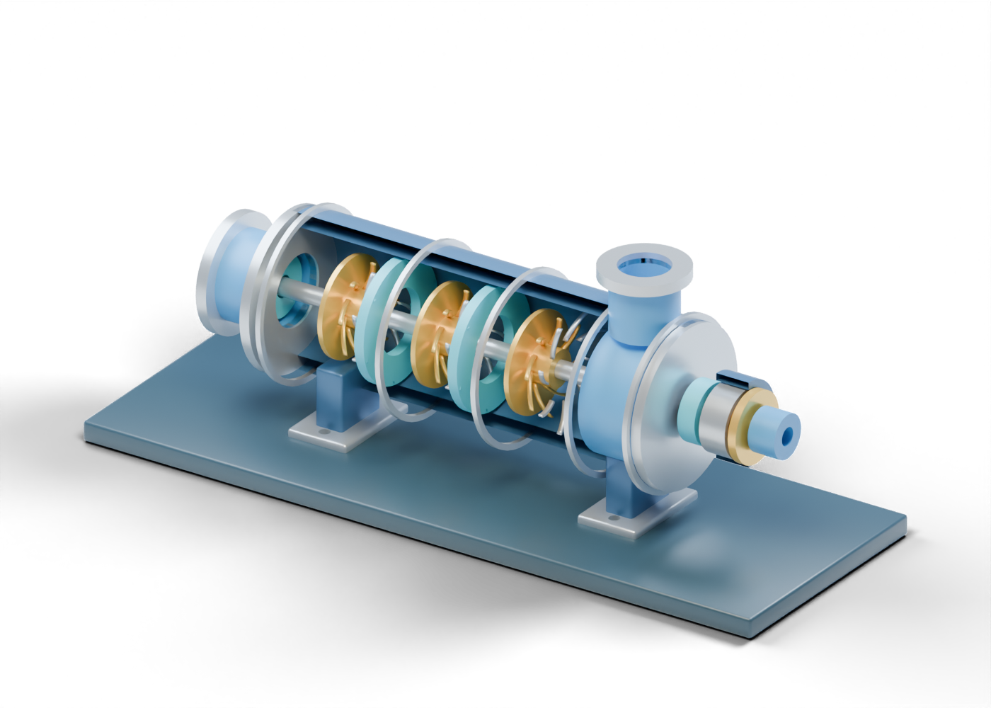
Compressor presentation baseplate
Studio support only, without foundation, alignment or guarding. Invented proportions; no selected machine, dimensions, gas, speed, pressure, performance map, surge line, rotor dynamics, seal-gas system, bearing load or service qualification.
Complete hollow compressor casing wall
Full invented barrel enclosure with one upper discharge bore. The inner space is not a verified gas passage. Invented proportions; no selected machine, dimensions, gas, speed, pressure, performance map, surge line, rotor dynamics, seal-gas system, bearing load or service qualification.
Suction end closure annulus
Open axial suction boundary at one end of the barrel. Invented proportions; no selected machine, dimensions, gas, speed, pressure, performance map, surge line, rotor dynamics, seal-gas system, bearing load or service qualification.
Drive end closure annulus
Separate end-boundary marker around the shaft. Invented proportions; no selected machine, dimensions, gas, speed, pressure, performance map, surge line, rotor dynamics, seal-gas system, bearing load or service qualification.
Open axial suction neck
Bored inlet neck; the selected gas and inlet conditions are unknown. Invented proportions; no selected machine, dimensions, gas, speed, pressure, performance map, surge line, rotor dynamics, seal-gas system, bearing load or service qualification.
Suction bored flange
Unrated open inlet flange marker. Invented proportions; no selected machine, dimensions, gas, speed, pressure, performance map, surge line, rotor dynamics, seal-gas system, bearing load or service qualification.
Open upper discharge neck
Bored discharge boundary over the real casing opening; no continuous interstage path or discharge condition is proved. Invented proportions; no selected machine, dimensions, gas, speed, pressure, performance map, surge line, rotor dynamics, seal-gas system, bearing load or service qualification.
Discharge bored flange
Unrated open outlet flange marker. Invented proportions; no selected machine, dimensions, gas, speed, pressure, performance map, surge line, rotor dynamics, seal-gas system, bearing load or service qualification.
Casing ring-joint location 1
External joint cue only; no casing split design or pressure integrity. Invented proportions; no selected machine, dimensions, gas, speed, pressure, performance map, surge line, rotor dynamics, seal-gas system, bearing load or service qualification.
Casing ring-joint location 2
External joint cue only; no casing split design or pressure integrity. Invented proportions; no selected machine, dimensions, gas, speed, pressure, performance map, surge line, rotor dynamics, seal-gas system, bearing load or service qualification.
Casing ring-joint location 3
External joint cue only; no casing split design or pressure integrity. Invented proportions; no selected machine, dimensions, gas, speed, pressure, performance map, surge line, rotor dynamics, seal-gas system, bearing load or service qualification.
Casing ring-joint location 4
External joint cue only; no casing split design or pressure integrity. Invented proportions; no selected machine, dimensions, gas, speed, pressure, performance map, surge line, rotor dynamics, seal-gas system, bearing load or service qualification.
Casing ring-joint location 5
External joint cue only; no casing split design or pressure integrity. Invented proportions; no selected machine, dimensions, gas, speed, pressure, performance map, surge line, rotor dynamics, seal-gas system, bearing load or service qualification.
Stage 1 rotor hub
Rotating-region hub marker on the common shaft. Invented proportions; no selected machine, dimensions, gas, speed, pressure, performance map, surge line, rotor dynamics, seal-gas system, bearing load or service qualification.
Stage 1 front impeller shroud
Separate annular impeller boundary; clearance is not selected. Invented proportions; no selected machine, dimensions, gas, speed, pressure, performance map, surge line, rotor dynamics, seal-gas system, bearing load or service qualification.
Stage 1 back impeller shroud
Separate annular impeller boundary; no stress or containment calculation. Invented proportions; no selected machine, dimensions, gas, speed, pressure, performance map, surge line, rotor dynamics, seal-gas system, bearing load or service qualification.
Stage 1 curved impeller vane 1
One invented static rotating-region vane; this profile has no aerodynamic or speed result. Invented proportions; no selected machine, dimensions, gas, speed, pressure, performance map, surge line, rotor dynamics, seal-gas system, bearing load or service qualification.
Stage 1 curved impeller vane 2
One invented static rotating-region vane; this profile has no aerodynamic or speed result. Invented proportions; no selected machine, dimensions, gas, speed, pressure, performance map, surge line, rotor dynamics, seal-gas system, bearing load or service qualification.
Stage 1 curved impeller vane 3
One invented static rotating-region vane; this profile has no aerodynamic or speed result. Invented proportions; no selected machine, dimensions, gas, speed, pressure, performance map, surge line, rotor dynamics, seal-gas system, bearing load or service qualification.
Stage 1 curved impeller vane 4
One invented static rotating-region vane; this profile has no aerodynamic or speed result. Invented proportions; no selected machine, dimensions, gas, speed, pressure, performance map, surge line, rotor dynamics, seal-gas system, bearing load or service qualification.
Stage 1 curved impeller vane 5
One invented static rotating-region vane; this profile has no aerodynamic or speed result. Invented proportions; no selected machine, dimensions, gas, speed, pressure, performance map, surge line, rotor dynamics, seal-gas system, bearing load or service qualification.
Stage 1 curved impeller vane 6
One invented static rotating-region vane; this profile has no aerodynamic or speed result. Invented proportions; no selected machine, dimensions, gas, speed, pressure, performance map, surge line, rotor dynamics, seal-gas system, bearing load or service qualification.
Stage 1 curved impeller vane 7
One invented static rotating-region vane; this profile has no aerodynamic or speed result. Invented proportions; no selected machine, dimensions, gas, speed, pressure, performance map, surge line, rotor dynamics, seal-gas system, bearing load or service qualification.
Stage 1 curved impeller vane 8
One invented static rotating-region vane; this profile has no aerodynamic or speed result. Invented proportions; no selected machine, dimensions, gas, speed, pressure, performance map, surge line, rotor dynamics, seal-gas system, bearing load or service qualification.
Stage 1 diffuser carrier
Stationary diffuser-region carrier, with a true centre opening. Invented proportions; no selected machine, dimensions, gas, speed, pressure, performance map, surge line, rotor dynamics, seal-gas system, bearing load or service qualification.
Stage 1 diffuser vane 1
Distinct stationary vane; kinetic-to-pressure conversion is a role, not a measured result. Invented proportions; no selected machine, dimensions, gas, speed, pressure, performance map, surge line, rotor dynamics, seal-gas system, bearing load or service qualification.
Stage 1 diffuser vane 2
Distinct stationary vane; kinetic-to-pressure conversion is a role, not a measured result. Invented proportions; no selected machine, dimensions, gas, speed, pressure, performance map, surge line, rotor dynamics, seal-gas system, bearing load or service qualification.
Stage 1 diffuser vane 3
Distinct stationary vane; kinetic-to-pressure conversion is a role, not a measured result. Invented proportions; no selected machine, dimensions, gas, speed, pressure, performance map, surge line, rotor dynamics, seal-gas system, bearing load or service qualification.
Stage 1 diffuser vane 4
Distinct stationary vane; kinetic-to-pressure conversion is a role, not a measured result. Invented proportions; no selected machine, dimensions, gas, speed, pressure, performance map, surge line, rotor dynamics, seal-gas system, bearing load or service qualification.
Stage 1 diffuser vane 5
Distinct stationary vane; kinetic-to-pressure conversion is a role, not a measured result. Invented proportions; no selected machine, dimensions, gas, speed, pressure, performance map, surge line, rotor dynamics, seal-gas system, bearing load or service qualification.
Stage 1 diffuser vane 6
Distinct stationary vane; kinetic-to-pressure conversion is a role, not a measured result. Invented proportions; no selected machine, dimensions, gas, speed, pressure, performance map, surge line, rotor dynamics, seal-gas system, bearing load or service qualification.
Stage 1 diffuser vane 7
Distinct stationary vane; kinetic-to-pressure conversion is a role, not a measured result. Invented proportions; no selected machine, dimensions, gas, speed, pressure, performance map, surge line, rotor dynamics, seal-gas system, bearing load or service qualification.
Stage 1 diffuser vane 8
Distinct stationary vane; kinetic-to-pressure conversion is a role, not a measured result. Invented proportions; no selected machine, dimensions, gas, speed, pressure, performance map, surge line, rotor dynamics, seal-gas system, bearing load or service qualification.
Stage 1 return-guide carrier
Separate interstage return-region cue; its passages are not an engineered gas path. Invented proportions; no selected machine, dimensions, gas, speed, pressure, performance map, surge line, rotor dynamics, seal-gas system, bearing load or service qualification.
Stage 1 return-guide vane 1
Static guide toward a following stage; no verified direction or loss result. Invented proportions; no selected machine, dimensions, gas, speed, pressure, performance map, surge line, rotor dynamics, seal-gas system, bearing load or service qualification.
Stage 1 return-guide vane 2
Static guide toward a following stage; no verified direction or loss result. Invented proportions; no selected machine, dimensions, gas, speed, pressure, performance map, surge line, rotor dynamics, seal-gas system, bearing load or service qualification.
Stage 1 return-guide vane 3
Static guide toward a following stage; no verified direction or loss result. Invented proportions; no selected machine, dimensions, gas, speed, pressure, performance map, surge line, rotor dynamics, seal-gas system, bearing load or service qualification.
Stage 1 return-guide vane 4
Static guide toward a following stage; no verified direction or loss result. Invented proportions; no selected machine, dimensions, gas, speed, pressure, performance map, surge line, rotor dynamics, seal-gas system, bearing load or service qualification.
Stage 1 return-guide vane 5
Static guide toward a following stage; no verified direction or loss result. Invented proportions; no selected machine, dimensions, gas, speed, pressure, performance map, surge line, rotor dynamics, seal-gas system, bearing load or service qualification.
Stage 1 return-guide vane 6
Static guide toward a following stage; no verified direction or loss result. Invented proportions; no selected machine, dimensions, gas, speed, pressure, performance map, surge line, rotor dynamics, seal-gas system, bearing load or service qualification.
Stage 2 rotor hub
Rotating-region hub marker on the common shaft. Invented proportions; no selected machine, dimensions, gas, speed, pressure, performance map, surge line, rotor dynamics, seal-gas system, bearing load or service qualification.
Stage 2 front impeller shroud
Separate annular impeller boundary; clearance is not selected. Invented proportions; no selected machine, dimensions, gas, speed, pressure, performance map, surge line, rotor dynamics, seal-gas system, bearing load or service qualification.
Stage 2 back impeller shroud
Separate annular impeller boundary; no stress or containment calculation. Invented proportions; no selected machine, dimensions, gas, speed, pressure, performance map, surge line, rotor dynamics, seal-gas system, bearing load or service qualification.
Stage 2 curved impeller vane 1
One invented static rotating-region vane; this profile has no aerodynamic or speed result. Invented proportions; no selected machine, dimensions, gas, speed, pressure, performance map, surge line, rotor dynamics, seal-gas system, bearing load or service qualification.
Stage 2 curved impeller vane 2
One invented static rotating-region vane; this profile has no aerodynamic or speed result. Invented proportions; no selected machine, dimensions, gas, speed, pressure, performance map, surge line, rotor dynamics, seal-gas system, bearing load or service qualification.
Stage 2 curved impeller vane 3
One invented static rotating-region vane; this profile has no aerodynamic or speed result. Invented proportions; no selected machine, dimensions, gas, speed, pressure, performance map, surge line, rotor dynamics, seal-gas system, bearing load or service qualification.
Stage 2 curved impeller vane 4
One invented static rotating-region vane; this profile has no aerodynamic or speed result. Invented proportions; no selected machine, dimensions, gas, speed, pressure, performance map, surge line, rotor dynamics, seal-gas system, bearing load or service qualification.
Stage 2 curved impeller vane 5
One invented static rotating-region vane; this profile has no aerodynamic or speed result. Invented proportions; no selected machine, dimensions, gas, speed, pressure, performance map, surge line, rotor dynamics, seal-gas system, bearing load or service qualification.
Stage 2 curved impeller vane 6
One invented static rotating-region vane; this profile has no aerodynamic or speed result. Invented proportions; no selected machine, dimensions, gas, speed, pressure, performance map, surge line, rotor dynamics, seal-gas system, bearing load or service qualification.
Stage 2 curved impeller vane 7
One invented static rotating-region vane; this profile has no aerodynamic or speed result. Invented proportions; no selected machine, dimensions, gas, speed, pressure, performance map, surge line, rotor dynamics, seal-gas system, bearing load or service qualification.
Stage 2 curved impeller vane 8
One invented static rotating-region vane; this profile has no aerodynamic or speed result. Invented proportions; no selected machine, dimensions, gas, speed, pressure, performance map, surge line, rotor dynamics, seal-gas system, bearing load or service qualification.
Stage 2 diffuser carrier
Stationary diffuser-region carrier, with a true centre opening. Invented proportions; no selected machine, dimensions, gas, speed, pressure, performance map, surge line, rotor dynamics, seal-gas system, bearing load or service qualification.
Stage 2 diffuser vane 1
Distinct stationary vane; kinetic-to-pressure conversion is a role, not a measured result. Invented proportions; no selected machine, dimensions, gas, speed, pressure, performance map, surge line, rotor dynamics, seal-gas system, bearing load or service qualification.
Stage 2 diffuser vane 2
Distinct stationary vane; kinetic-to-pressure conversion is a role, not a measured result. Invented proportions; no selected machine, dimensions, gas, speed, pressure, performance map, surge line, rotor dynamics, seal-gas system, bearing load or service qualification.
Stage 2 diffuser vane 3
Distinct stationary vane; kinetic-to-pressure conversion is a role, not a measured result. Invented proportions; no selected machine, dimensions, gas, speed, pressure, performance map, surge line, rotor dynamics, seal-gas system, bearing load or service qualification.
Stage 2 diffuser vane 4
Distinct stationary vane; kinetic-to-pressure conversion is a role, not a measured result. Invented proportions; no selected machine, dimensions, gas, speed, pressure, performance map, surge line, rotor dynamics, seal-gas system, bearing load or service qualification.
Stage 2 diffuser vane 5
Distinct stationary vane; kinetic-to-pressure conversion is a role, not a measured result. Invented proportions; no selected machine, dimensions, gas, speed, pressure, performance map, surge line, rotor dynamics, seal-gas system, bearing load or service qualification.
Stage 2 diffuser vane 6
Distinct stationary vane; kinetic-to-pressure conversion is a role, not a measured result. Invented proportions; no selected machine, dimensions, gas, speed, pressure, performance map, surge line, rotor dynamics, seal-gas system, bearing load or service qualification.
Stage 2 diffuser vane 7
Distinct stationary vane; kinetic-to-pressure conversion is a role, not a measured result. Invented proportions; no selected machine, dimensions, gas, speed, pressure, performance map, surge line, rotor dynamics, seal-gas system, bearing load or service qualification.
Stage 2 diffuser vane 8
Distinct stationary vane; kinetic-to-pressure conversion is a role, not a measured result. Invented proportions; no selected machine, dimensions, gas, speed, pressure, performance map, surge line, rotor dynamics, seal-gas system, bearing load or service qualification.
Stage 2 return-guide carrier
Separate interstage return-region cue; its passages are not an engineered gas path. Invented proportions; no selected machine, dimensions, gas, speed, pressure, performance map, surge line, rotor dynamics, seal-gas system, bearing load or service qualification.
Stage 2 return-guide vane 1
Static guide toward a following stage; no verified direction or loss result. Invented proportions; no selected machine, dimensions, gas, speed, pressure, performance map, surge line, rotor dynamics, seal-gas system, bearing load or service qualification.
Stage 2 return-guide vane 2
Static guide toward a following stage; no verified direction or loss result. Invented proportions; no selected machine, dimensions, gas, speed, pressure, performance map, surge line, rotor dynamics, seal-gas system, bearing load or service qualification.
Stage 2 return-guide vane 3
Static guide toward a following stage; no verified direction or loss result. Invented proportions; no selected machine, dimensions, gas, speed, pressure, performance map, surge line, rotor dynamics, seal-gas system, bearing load or service qualification.
Stage 2 return-guide vane 4
Static guide toward a following stage; no verified direction or loss result. Invented proportions; no selected machine, dimensions, gas, speed, pressure, performance map, surge line, rotor dynamics, seal-gas system, bearing load or service qualification.
Stage 2 return-guide vane 5
Static guide toward a following stage; no verified direction or loss result. Invented proportions; no selected machine, dimensions, gas, speed, pressure, performance map, surge line, rotor dynamics, seal-gas system, bearing load or service qualification.
Stage 2 return-guide vane 6
Static guide toward a following stage; no verified direction or loss result. Invented proportions; no selected machine, dimensions, gas, speed, pressure, performance map, surge line, rotor dynamics, seal-gas system, bearing load or service qualification.
Stage 3 rotor hub
Rotating-region hub marker on the common shaft. Invented proportions; no selected machine, dimensions, gas, speed, pressure, performance map, surge line, rotor dynamics, seal-gas system, bearing load or service qualification.
Stage 3 front impeller shroud
Separate annular impeller boundary; clearance is not selected. Invented proportions; no selected machine, dimensions, gas, speed, pressure, performance map, surge line, rotor dynamics, seal-gas system, bearing load or service qualification.
Stage 3 back impeller shroud
Separate annular impeller boundary; no stress or containment calculation. Invented proportions; no selected machine, dimensions, gas, speed, pressure, performance map, surge line, rotor dynamics, seal-gas system, bearing load or service qualification.
Stage 3 curved impeller vane 1
One invented static rotating-region vane; this profile has no aerodynamic or speed result. Invented proportions; no selected machine, dimensions, gas, speed, pressure, performance map, surge line, rotor dynamics, seal-gas system, bearing load or service qualification.
Stage 3 curved impeller vane 2
One invented static rotating-region vane; this profile has no aerodynamic or speed result. Invented proportions; no selected machine, dimensions, gas, speed, pressure, performance map, surge line, rotor dynamics, seal-gas system, bearing load or service qualification.
Stage 3 curved impeller vane 3
One invented static rotating-region vane; this profile has no aerodynamic or speed result. Invented proportions; no selected machine, dimensions, gas, speed, pressure, performance map, surge line, rotor dynamics, seal-gas system, bearing load or service qualification.
Stage 3 curved impeller vane 4
One invented static rotating-region vane; this profile has no aerodynamic or speed result. Invented proportions; no selected machine, dimensions, gas, speed, pressure, performance map, surge line, rotor dynamics, seal-gas system, bearing load or service qualification.
Stage 3 curved impeller vane 5
One invented static rotating-region vane; this profile has no aerodynamic or speed result. Invented proportions; no selected machine, dimensions, gas, speed, pressure, performance map, surge line, rotor dynamics, seal-gas system, bearing load or service qualification.
Stage 3 curved impeller vane 6
One invented static rotating-region vane; this profile has no aerodynamic or speed result. Invented proportions; no selected machine, dimensions, gas, speed, pressure, performance map, surge line, rotor dynamics, seal-gas system, bearing load or service qualification.
Stage 3 curved impeller vane 7
One invented static rotating-region vane; this profile has no aerodynamic or speed result. Invented proportions; no selected machine, dimensions, gas, speed, pressure, performance map, surge line, rotor dynamics, seal-gas system, bearing load or service qualification.
Stage 3 curved impeller vane 8
One invented static rotating-region vane; this profile has no aerodynamic or speed result. Invented proportions; no selected machine, dimensions, gas, speed, pressure, performance map, surge line, rotor dynamics, seal-gas system, bearing load or service qualification.
Stage 3 diffuser carrier
Stationary diffuser-region carrier, with a true centre opening. Invented proportions; no selected machine, dimensions, gas, speed, pressure, performance map, surge line, rotor dynamics, seal-gas system, bearing load or service qualification.
Stage 3 diffuser vane 1
Distinct stationary vane; kinetic-to-pressure conversion is a role, not a measured result. Invented proportions; no selected machine, dimensions, gas, speed, pressure, performance map, surge line, rotor dynamics, seal-gas system, bearing load or service qualification.
Stage 3 diffuser vane 2
Distinct stationary vane; kinetic-to-pressure conversion is a role, not a measured result. Invented proportions; no selected machine, dimensions, gas, speed, pressure, performance map, surge line, rotor dynamics, seal-gas system, bearing load or service qualification.
Stage 3 diffuser vane 3
Distinct stationary vane; kinetic-to-pressure conversion is a role, not a measured result. Invented proportions; no selected machine, dimensions, gas, speed, pressure, performance map, surge line, rotor dynamics, seal-gas system, bearing load or service qualification.
Stage 3 diffuser vane 4
Distinct stationary vane; kinetic-to-pressure conversion is a role, not a measured result. Invented proportions; no selected machine, dimensions, gas, speed, pressure, performance map, surge line, rotor dynamics, seal-gas system, bearing load or service qualification.
Stage 3 diffuser vane 5
Distinct stationary vane; kinetic-to-pressure conversion is a role, not a measured result. Invented proportions; no selected machine, dimensions, gas, speed, pressure, performance map, surge line, rotor dynamics, seal-gas system, bearing load or service qualification.
Stage 3 diffuser vane 6
Distinct stationary vane; kinetic-to-pressure conversion is a role, not a measured result. Invented proportions; no selected machine, dimensions, gas, speed, pressure, performance map, surge line, rotor dynamics, seal-gas system, bearing load or service qualification.
Stage 3 diffuser vane 7
Distinct stationary vane; kinetic-to-pressure conversion is a role, not a measured result. Invented proportions; no selected machine, dimensions, gas, speed, pressure, performance map, surge line, rotor dynamics, seal-gas system, bearing load or service qualification.
Stage 3 diffuser vane 8
Distinct stationary vane; kinetic-to-pressure conversion is a role, not a measured result. Invented proportions; no selected machine, dimensions, gas, speed, pressure, performance map, surge line, rotor dynamics, seal-gas system, bearing load or service qualification.
Final annular discharge collector location
Stationary final-stage collection region; this annulus is not a designed volute or continuous outlet passage. Invented proportions; no selected machine, dimensions, gas, speed, pressure, performance map, surge line, rotor dynamics, seal-gas system, bearing load or service qualification.
Common static compressor shaft
Common rotor-axis cue, without rotation, critical-speed or coupling analysis. Invented proportions; no selected machine, dimensions, gas, speed, pressure, performance map, surge line, rotor dynamics, seal-gas system, bearing load or service qualification.
Suction dry-gas-seal cartridge location
Seal location only: no faces, film, buffer-gas circuit, vent or emissions qualification. Invented proportions; no selected machine, dimensions, gas, speed, pressure, performance map, surge line, rotor dynamics, seal-gas system, bearing load or service qualification.
Suction separation-ring location
Boundary cue between process and bearing regions; no seal function demonstrated. Invented proportions; no selected machine, dimensions, gas, speed, pressure, performance map, surge line, rotor dynamics, seal-gas system, bearing load or service qualification.
Drive dry-gas-seal cartridge location
Seal location only: no faces, film, buffer-gas circuit, vent or emissions qualification. Invented proportions; no selected machine, dimensions, gas, speed, pressure, performance map, surge line, rotor dynamics, seal-gas system, bearing load or service qualification.
Drive separation-ring location
Boundary cue between process and bearing regions; no seal function demonstrated. Invented proportions; no selected machine, dimensions, gas, speed, pressure, performance map, surge line, rotor dynamics, seal-gas system, bearing load or service qualification.
Suction complete bearing housing wall
Separate full enclosure for an illustrative shaft-support region. Invented proportions; no selected machine, dimensions, gas, speed, pressure, performance map, surge line, rotor dynamics, seal-gas system, bearing load or service qualification.
Suction bearing journal sleeve marker
Unqualified journal-sleeve location. Invented proportions; no selected machine, dimensions, gas, speed, pressure, performance map, surge line, rotor dynamics, seal-gas system, bearing load or service qualification.
Suction bearing outer carrier
Carrier-location marker, not selected bearing technology or load capacity. Invented proportions; no selected machine, dimensions, gas, speed, pressure, performance map, surge line, rotor dynamics, seal-gas system, bearing load or service qualification.
Suction bearing pad cue 1
Static pad-location cue; no oil film, clearance or bearing performance. Invented proportions; no selected machine, dimensions, gas, speed, pressure, performance map, surge line, rotor dynamics, seal-gas system, bearing load or service qualification.
Suction bearing pad cue 2
Static pad-location cue; no oil film, clearance or bearing performance. Invented proportions; no selected machine, dimensions, gas, speed, pressure, performance map, surge line, rotor dynamics, seal-gas system, bearing load or service qualification.
Suction bearing pad cue 3
Static pad-location cue; no oil film, clearance or bearing performance. Invented proportions; no selected machine, dimensions, gas, speed, pressure, performance map, surge line, rotor dynamics, seal-gas system, bearing load or service qualification.
Suction bearing pad cue 4
Static pad-location cue; no oil film, clearance or bearing performance. Invented proportions; no selected machine, dimensions, gas, speed, pressure, performance map, surge line, rotor dynamics, seal-gas system, bearing load or service qualification.
Suction bearing pad cue 5
Static pad-location cue; no oil film, clearance or bearing performance. Invented proportions; no selected machine, dimensions, gas, speed, pressure, performance map, surge line, rotor dynamics, seal-gas system, bearing load or service qualification.
Suction bearing pad cue 6
Static pad-location cue; no oil film, clearance or bearing performance. Invented proportions; no selected machine, dimensions, gas, speed, pressure, performance map, surge line, rotor dynamics, seal-gas system, bearing load or service qualification.
Suction bearing pad cue 7
Static pad-location cue; no oil film, clearance or bearing performance. Invented proportions; no selected machine, dimensions, gas, speed, pressure, performance map, surge line, rotor dynamics, seal-gas system, bearing load or service qualification.
Suction bearing pad cue 8
Static pad-location cue; no oil film, clearance or bearing performance. Invented proportions; no selected machine, dimensions, gas, speed, pressure, performance map, surge line, rotor dynamics, seal-gas system, bearing load or service qualification.
Drive complete bearing housing wall
Separate full enclosure for an illustrative shaft-support region. Invented proportions; no selected machine, dimensions, gas, speed, pressure, performance map, surge line, rotor dynamics, seal-gas system, bearing load or service qualification.
Drive bearing journal sleeve marker
Unqualified journal-sleeve location. Invented proportions; no selected machine, dimensions, gas, speed, pressure, performance map, surge line, rotor dynamics, seal-gas system, bearing load or service qualification.
Drive bearing outer carrier
Carrier-location marker, not selected bearing technology or load capacity. Invented proportions; no selected machine, dimensions, gas, speed, pressure, performance map, surge line, rotor dynamics, seal-gas system, bearing load or service qualification.
Drive bearing pad cue 1
Static pad-location cue; no oil film, clearance or bearing performance. Invented proportions; no selected machine, dimensions, gas, speed, pressure, performance map, surge line, rotor dynamics, seal-gas system, bearing load or service qualification.
Drive bearing pad cue 2
Static pad-location cue; no oil film, clearance or bearing performance. Invented proportions; no selected machine, dimensions, gas, speed, pressure, performance map, surge line, rotor dynamics, seal-gas system, bearing load or service qualification.
Drive bearing pad cue 3
Static pad-location cue; no oil film, clearance or bearing performance. Invented proportions; no selected machine, dimensions, gas, speed, pressure, performance map, surge line, rotor dynamics, seal-gas system, bearing load or service qualification.
Drive bearing pad cue 4
Static pad-location cue; no oil film, clearance or bearing performance. Invented proportions; no selected machine, dimensions, gas, speed, pressure, performance map, surge line, rotor dynamics, seal-gas system, bearing load or service qualification.
Drive bearing pad cue 5
Static pad-location cue; no oil film, clearance or bearing performance. Invented proportions; no selected machine, dimensions, gas, speed, pressure, performance map, surge line, rotor dynamics, seal-gas system, bearing load or service qualification.
Drive bearing pad cue 6
Static pad-location cue; no oil film, clearance or bearing performance. Invented proportions; no selected machine, dimensions, gas, speed, pressure, performance map, surge line, rotor dynamics, seal-gas system, bearing load or service qualification.
Drive bearing pad cue 7
Static pad-location cue; no oil film, clearance or bearing performance. Invented proportions; no selected machine, dimensions, gas, speed, pressure, performance map, surge line, rotor dynamics, seal-gas system, bearing load or service qualification.
Drive bearing pad cue 8
Static pad-location cue; no oil film, clearance or bearing performance. Invented proportions; no selected machine, dimensions, gas, speed, pressure, performance map, surge line, rotor dynamics, seal-gas system, bearing load or service qualification.
Drive-end thrust-disc location
Axial-restraint role marker, without a thrust result. Invented proportions; no selected machine, dimensions, gas, speed, pressure, performance map, surge line, rotor dynamics, seal-gas system, bearing load or service qualification.
Drive coupling-hub location
Drive interface only; no motor, gearbox or guard is modeled. Invented proportions; no selected machine, dimensions, gas, speed, pressure, performance map, surge line, rotor dynamics, seal-gas system, bearing load or service qualification.
Compressor display pedestal 1
Display support, not a centreline mount. Invented proportions; no selected machine, dimensions, gas, speed, pressure, performance map, surge line, rotor dynamics, seal-gas system, bearing load or service qualification.
Bored compressor display foot 1
Drilled visual foot; no anchor, grout or skid design. Invented proportions; no selected machine, dimensions, gas, speed, pressure, performance map, surge line, rotor dynamics, seal-gas system, bearing load or service qualification.
Compressor display pedestal 2
Display support, not a centreline mount. Invented proportions; no selected machine, dimensions, gas, speed, pressure, performance map, surge line, rotor dynamics, seal-gas system, bearing load or service qualification.
Bored compressor display foot 2
Drilled visual foot; no anchor, grout or skid design. Invented proportions; no selected machine, dimensions, gas, speed, pressure, performance map, surge line, rotor dynamics, seal-gas system, bearing load or service qualification.