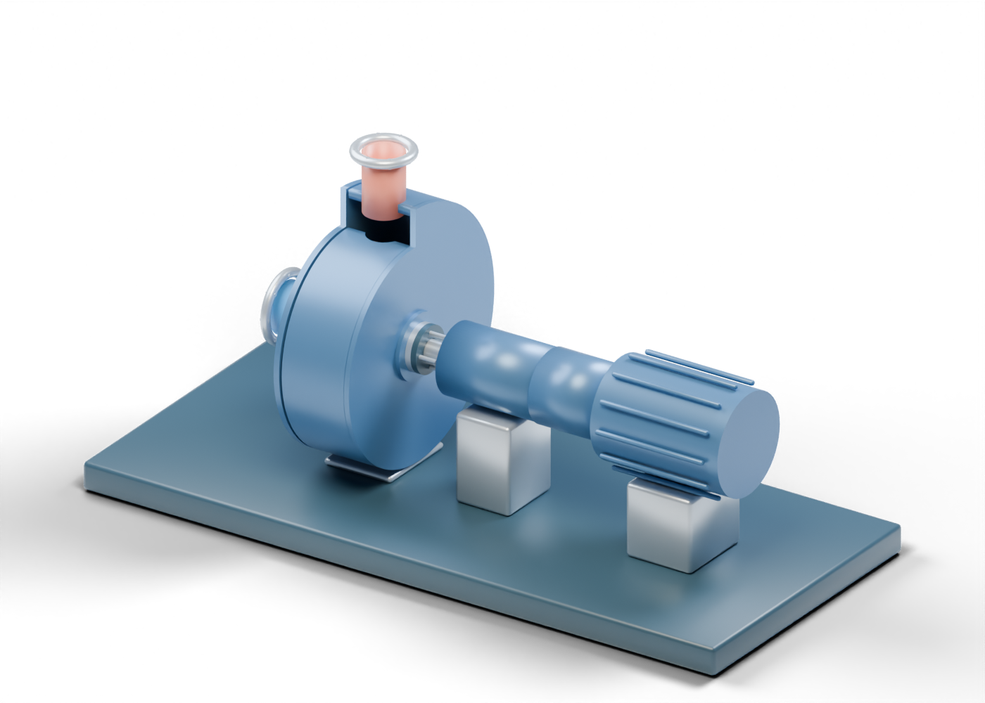
Base frame
Illustrative support frame; foundations and structural design vary.
Volute casing wall
A generic widening spiral surrounds the impeller, with a geometric discharge opening. This teaching contour is not hydraulically designed.
Suction-side casing cover
Encloses a side of the volute; this generic cover has a geometric central bore.
Drive-side casing cover
Encloses a side of the volute; this generic cover has a geometric central bore.
Suction inlet
Hollow generic connection with illustrative wall thickness. Welds, facing and pressure ratings are not specified.
Suction inlet flange
Illustrative flange ring, with no rated facing or bolt specification.
Suction inlet fastener 1
Generic fastener position. Quantity and size do not specify a rated connection.
Suction inlet fastener 2
Generic fastener position. Quantity and size do not specify a rated connection.
Suction inlet fastener 3
Generic fastener position. Quantity and size do not specify a rated connection.
Suction inlet fastener 4
Generic fastener position. Quantity and size do not specify a rated connection.
Suction inlet fastener 5
Generic fastener position. Quantity and size do not specify a rated connection.
Suction inlet fastener 6
Generic fastener position. Quantity and size do not specify a rated connection.
Suction inlet fastener 7
Generic fastener position. Quantity and size do not specify a rated connection.
Suction inlet fastener 8
Generic fastener position. Quantity and size do not specify a rated connection.
Discharge outlet
Hollow generic connection with illustrative wall thickness. Welds, facing and pressure ratings are not specified.
Discharge outlet flange
Illustrative flange ring, with no rated facing or bolt specification.
Discharge outlet fastener 1
Generic fastener position. Quantity and size do not specify a rated connection.
Discharge outlet fastener 2
Generic fastener position. Quantity and size do not specify a rated connection.
Discharge outlet fastener 3
Generic fastener position. Quantity and size do not specify a rated connection.
Discharge outlet fastener 4
Generic fastener position. Quantity and size do not specify a rated connection.
Discharge outlet fastener 5
Generic fastener position. Quantity and size do not specify a rated connection.
Discharge outlet fastener 6
Generic fastener position. Quantity and size do not specify a rated connection.
Discharge outlet fastener 7
Generic fastener position. Quantity and size do not specify a rated connection.
Discharge outlet fastener 8
Generic fastener position. Quantity and size do not specify a rated connection.
Impeller back shroud
Back plate bounds the impeller flow passages. Thickness and contour are illustrative.
Impeller front shroud
Front plate of this closed-impeller concept. Reveal internals hides it to expose the vanes.
Impeller hub
Connects the impeller assembly around the shaft. Keying and fit are illustrative.
Curved impeller vane 1
Curved teaching vane forms a passage between the shrouds. Shape, count and clearances are illustrative, without a pump curve.
Curved impeller vane 2
Curved teaching vane forms a passage between the shrouds. Shape, count and clearances are illustrative, without a pump curve.
Curved impeller vane 3
Curved teaching vane forms a passage between the shrouds. Shape, count and clearances are illustrative, without a pump curve.
Curved impeller vane 4
Curved teaching vane forms a passage between the shrouds. Shape, count and clearances are illustrative, without a pump curve.
Curved impeller vane 5
Curved teaching vane forms a passage between the shrouds. Shape, count and clearances are illustrative, without a pump curve.
Curved impeller vane 6
Curved teaching vane forms a passage between the shrouds. Shape, count and clearances are illustrative, without a pump curve.
Curved impeller vane 7
Curved teaching vane forms a passage between the shrouds. Shape, count and clearances are illustrative, without a pump curve.
Shaft
Transfers drive rotation to the impeller. This schematic omits verified fits, fatigue and torque calculations.
Shaft key
Illustrates a keyed connection; key dimensions and stresses are not specified.
Casing wear ring
Conceptual stationary clearance ring at the suction eye. No clearance or wear limit is specified.
Stationary seal face
Conceptual stationary annular face in a mechanical seal. Materials and seal balance are not specified.
Rotating seal face
Conceptual rotating face adjacent to the stationary face. No leakage or temperature performance is implied.
Seal gland
Generic gland around the shaft; seal-flush piping and cartridge design are omitted.
Seal spring 1
Schematic spring-position marker, not a helical spring or verified face-loading design.
Seal spring 2
Schematic spring-position marker, not a helical spring or verified face-loading design.
Seal spring 3
Schematic spring-position marker, not a helical spring or verified face-loading design.
Seal spring 4
Schematic spring-position marker, not a helical spring or verified face-loading design.
Bearing outer race -0.15
Generic stationary outer bearing race, without load rating or lubrication design.
Bearing inner race -0.15
Generic shaft-side race. Bearing performance and fits are not specified.
Bearing ball -0.15 / 1
Schematic rolling element; this static bearing does not simulate cage or rolling kinematics.
Bearing ball -0.15 / 2
Schematic rolling element; this static bearing does not simulate cage or rolling kinematics.
Bearing ball -0.15 / 3
Schematic rolling element; this static bearing does not simulate cage or rolling kinematics.
Bearing ball -0.15 / 4
Schematic rolling element; this static bearing does not simulate cage or rolling kinematics.
Bearing ball -0.15 / 5
Schematic rolling element; this static bearing does not simulate cage or rolling kinematics.
Bearing ball -0.15 / 6
Schematic rolling element; this static bearing does not simulate cage or rolling kinematics.
Bearing ball -0.15 / 7
Schematic rolling element; this static bearing does not simulate cage or rolling kinematics.
Bearing ball -0.15 / 8
Schematic rolling element; this static bearing does not simulate cage or rolling kinematics.
Bearing ball -0.15 / 9
Schematic rolling element; this static bearing does not simulate cage or rolling kinematics.
Bearing ball -0.15 / 10
Schematic rolling element; this static bearing does not simulate cage or rolling kinematics.
Bearing outer race 0.35
Generic stationary outer bearing race, without load rating or lubrication design.
Bearing inner race 0.35
Generic shaft-side race. Bearing performance and fits are not specified.
Bearing ball 0.35 / 1
Schematic rolling element; this static bearing does not simulate cage or rolling kinematics.
Bearing ball 0.35 / 2
Schematic rolling element; this static bearing does not simulate cage or rolling kinematics.
Bearing ball 0.35 / 3
Schematic rolling element; this static bearing does not simulate cage or rolling kinematics.
Bearing ball 0.35 / 4
Schematic rolling element; this static bearing does not simulate cage or rolling kinematics.
Bearing ball 0.35 / 5
Schematic rolling element; this static bearing does not simulate cage or rolling kinematics.
Bearing ball 0.35 / 6
Schematic rolling element; this static bearing does not simulate cage or rolling kinematics.
Bearing ball 0.35 / 7
Schematic rolling element; this static bearing does not simulate cage or rolling kinematics.
Bearing ball 0.35 / 8
Schematic rolling element; this static bearing does not simulate cage or rolling kinematics.
Bearing ball 0.35 / 9
Schematic rolling element; this static bearing does not simulate cage or rolling kinematics.
Bearing ball 0.35 / 10
Schematic rolling element; this static bearing does not simulate cage or rolling kinematics.
Bearing housing
Generic bearing enclosure; lubrication passages are omitted.
Pump coupling half
Conceptual shaft coupling half; alignment tolerances and guard design are omitted.
Flexible coupling element
Generic flexible-element position between coupling halves. No elastomer specification or torque capacity.
Motor coupling half
Conceptual motor-side coupling half. No alignment procedure is supplied.
Coupling guard
Simplified removable guard around the coupling; not a certified guarding design.
Motor body
A generic electric drive enclosure; electrical internals are omitted.
Motor cooling fin 1
Illustrative external cooling fin. No motor thermal rating is implied.
Motor cooling fin 2
Illustrative external cooling fin. No motor thermal rating is implied.
Motor cooling fin 3
Illustrative external cooling fin. No motor thermal rating is implied.
Motor cooling fin 4
Illustrative external cooling fin. No motor thermal rating is implied.
Motor cooling fin 5
Illustrative external cooling fin. No motor thermal rating is implied.
Motor cooling fin 6
Illustrative external cooling fin. No motor thermal rating is implied.
Motor cooling fin 7
Illustrative external cooling fin. No motor thermal rating is implied.
Motor cooling fin 8
Illustrative external cooling fin. No motor thermal rating is implied.
Motor cooling fin 9
Illustrative external cooling fin. No motor thermal rating is implied.
Motor cooling fin 10
Illustrative external cooling fin. No motor thermal rating is implied.
Motor cooling fin 11
Illustrative external cooling fin. No motor thermal rating is implied.
Motor cooling fin 12
Illustrative external cooling fin. No motor thermal rating is implied.
Motor rotor marker
Simple drive rotor marker; windings, magnetic fields and speed are not modeled.
Casing foot
Illustrative low attachment beneath the casing. This foot stays clear of the impeller envelope; foundation loads are not designed.
Bearing pedestal
Supports the bearing housing beneath the shaft line. Foundation and alignment details are not specified.
Motor pedestal
Supports the generic motor enclosure. Mounting feet and foundation loads are illustrative.