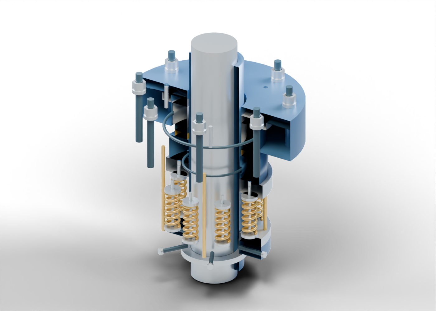
Shaft segment
Solid smooth shaft segment establishing the axis. No machine dimensions, surface finish or running clearance.
Hollow shaft sleeve
Separate hollow sleeve around the shaft with an internal secondary-seal recess. Clearance and axial position are invented.
Sleeve secondary seal
Original toroidal sleeve-to-shaft seal marker in a separate recess; compression and a rated joint are not established.
Sleeve shoulder marker
Annular stop concept; no qualified axial retention or installation setting.
Drive collar
Rotating-side drive collar concept with six radial smooth screw bores. No clamping or torque qualification.
Spring backing ring
Backing behind eight separate springs. This invented spring arrangement is static.
Spring pressure ring
Annular pressure-ring concept between springs and the rotating face carrier. Axial forces are not calculated.
Rotating face carrier
Hollow rotating-side carrier with an internal secondary-seal recess. Proportions and fits are original teaching choices.
Rotating secondary seal
Separate toroidal ring in an invented carrier recess. It depicts a secondary sealing location, not elastomer deformation or leakage performance.
Rotating seal face
Separate annular rotating face. Its upper planar boundary meets the stationary face in the static geometric pose; no film or lapping performance.
Stationary seal face
Separate annular stationary face with a matching face plane. Material, microscopic film and leakage are unspecified.
Stationary seat support
Hollow support behind the stationary face with an outer secondary-seal recess. It remains separate from the rotating carrier.
Stationary secondary seal
Separate toroidal seat-to-gland seal marker. Fit and compression remain unqualified.
Gland seat pocket
Bored stationary gland pocket surrounding the seat. Reveal removes it visually; no removal procedure.
Gland shoulder
Annular gland back shoulder with shaft clearance and eight real fastener bores. No pressure design or rated joint.
Stationary seat retainer
Annular retention marker behind the stationary support, with three bored anti-rotation-pin positions. No retention/load qualification.
Stationary locating pin 1
Stationary smooth locating-pin marker across the retainer and gland shoulder. No rated anti-rotation design.
Stationary locating pin 2
Stationary smooth locating-pin marker across the retainer and gland shoulder. No rated anti-rotation design.
Stationary locating pin 3
Stationary smooth locating-pin marker across the retainer and gland shoulder. No rated anti-rotation design.
Coil spring 1
Original closed six-turn coil marker. Static geometry; no spring force, preload, fatigue or deflection calculation.
Spring guide pin 1
Smooth guide inside the spring envelope. Geometric guiding concept only; buckling and rotating dynamics are not calculated.
Rear spring seat 1
Separate bored spring-seat marker. End seating is illustrative, not a qualified contact or preload.
Front spring seat 1
Separate bored seat between the coil and pressure ring; not a service or assembly sequence.
Coil spring 2
Original closed six-turn coil marker. Static geometry; no spring force, preload, fatigue or deflection calculation.
Spring guide pin 2
Smooth guide inside the spring envelope. Geometric guiding concept only; buckling and rotating dynamics are not calculated.
Rear spring seat 2
Separate bored spring-seat marker. End seating is illustrative, not a qualified contact or preload.
Front spring seat 2
Separate bored seat between the coil and pressure ring; not a service or assembly sequence.
Coil spring 3
Original closed six-turn coil marker. Static geometry; no spring force, preload, fatigue or deflection calculation.
Spring guide pin 3
Smooth guide inside the spring envelope. Geometric guiding concept only; buckling and rotating dynamics are not calculated.
Rear spring seat 3
Separate bored spring-seat marker. End seating is illustrative, not a qualified contact or preload.
Front spring seat 3
Separate bored seat between the coil and pressure ring; not a service or assembly sequence.
Coil spring 4
Original closed six-turn coil marker. Static geometry; no spring force, preload, fatigue or deflection calculation.
Spring guide pin 4
Smooth guide inside the spring envelope. Geometric guiding concept only; buckling and rotating dynamics are not calculated.
Rear spring seat 4
Separate bored spring-seat marker. End seating is illustrative, not a qualified contact or preload.
Front spring seat 4
Separate bored seat between the coil and pressure ring; not a service or assembly sequence.
Coil spring 5
Original closed six-turn coil marker. Static geometry; no spring force, preload, fatigue or deflection calculation.
Spring guide pin 5
Smooth guide inside the spring envelope. Geometric guiding concept only; buckling and rotating dynamics are not calculated.
Rear spring seat 5
Separate bored spring-seat marker. End seating is illustrative, not a qualified contact or preload.
Front spring seat 5
Separate bored seat between the coil and pressure ring; not a service or assembly sequence.
Coil spring 6
Original closed six-turn coil marker. Static geometry; no spring force, preload, fatigue or deflection calculation.
Spring guide pin 6
Smooth guide inside the spring envelope. Geometric guiding concept only; buckling and rotating dynamics are not calculated.
Rear spring seat 6
Separate bored spring-seat marker. End seating is illustrative, not a qualified contact or preload.
Front spring seat 6
Separate bored seat between the coil and pressure ring; not a service or assembly sequence.
Coil spring 7
Original closed six-turn coil marker. Static geometry; no spring force, preload, fatigue or deflection calculation.
Spring guide pin 7
Smooth guide inside the spring envelope. Geometric guiding concept only; buckling and rotating dynamics are not calculated.
Rear spring seat 7
Separate bored spring-seat marker. End seating is illustrative, not a qualified contact or preload.
Front spring seat 7
Separate bored seat between the coil and pressure ring; not a service or assembly sequence.
Coil spring 8
Original closed six-turn coil marker. Static geometry; no spring force, preload, fatigue or deflection calculation.
Spring guide pin 8
Smooth guide inside the spring envelope. Geometric guiding concept only; buckling and rotating dynamics are not calculated.
Rear spring seat 8
Separate bored spring-seat marker. End seating is illustrative, not a qualified contact or preload.
Front spring seat 8
Separate bored seat between the coil and pressure ring; not a service or assembly sequence.
Rotating drive pin 1
Smooth axial drive-pin concept joining backing and rotating carrier. Torque, wear and axial compliance are not qualified.
Rotating drive pin 2
Smooth axial drive-pin concept joining backing and rotating carrier. Torque, wear and axial compliance are not qualified.
Rotating drive pin 3
Smooth axial drive-pin concept joining backing and rotating carrier. Torque, wear and axial compliance are not qualified.
Rotating drive pin 4
Smooth axial drive-pin concept joining backing and rotating carrier. Torque, wear and axial compliance are not qualified.
Radial collar screw 1
Unthreaded smooth radial clamping-screw marker meeting the sleeve envelope. No qualified engagement, tightening instruction or clamping force.
Collar screw head 1
Original six-sided screw-head marker, without a drive recess or thread form.
Radial collar screw 2
Unthreaded smooth radial clamping-screw marker meeting the sleeve envelope. No qualified engagement, tightening instruction or clamping force.
Collar screw head 2
Original six-sided screw-head marker, without a drive recess or thread form.
Radial collar screw 3
Unthreaded smooth radial clamping-screw marker meeting the sleeve envelope. No qualified engagement, tightening instruction or clamping force.
Collar screw head 3
Original six-sided screw-head marker, without a drive recess or thread form.
Radial collar screw 4
Unthreaded smooth radial clamping-screw marker meeting the sleeve envelope. No qualified engagement, tightening instruction or clamping force.
Collar screw head 4
Original six-sided screw-head marker, without a drive recess or thread form.
Radial collar screw 5
Unthreaded smooth radial clamping-screw marker meeting the sleeve envelope. No qualified engagement, tightening instruction or clamping force.
Collar screw head 5
Original six-sided screw-head marker, without a drive recess or thread form.
Radial collar screw 6
Unthreaded smooth radial clamping-screw marker meeting the sleeve envelope. No qualified engagement, tightening instruction or clamping force.
Collar screw head 6
Original six-sided screw-head marker, without a drive recess or thread form.
Gland stud 1
Smooth fastening stud marker. Threads and the adjoining machine housing are omitted.
Gland washer 1
Separate annular washer with an actual stud opening. No bolt preload or torque.
Gland nut 1
Separate six-sided nut marker with a circular unthreaded stud bore.
Gland stud 2
Smooth fastening stud marker. Threads and the adjoining machine housing are omitted.
Gland washer 2
Separate annular washer with an actual stud opening. No bolt preload or torque.
Gland nut 2
Separate six-sided nut marker with a circular unthreaded stud bore.
Gland stud 3
Smooth fastening stud marker. Threads and the adjoining machine housing are omitted.
Gland washer 3
Separate annular washer with an actual stud opening. No bolt preload or torque.
Gland nut 3
Separate six-sided nut marker with a circular unthreaded stud bore.
Gland stud 4
Smooth fastening stud marker. Threads and the adjoining machine housing are omitted.
Gland washer 4
Separate annular washer with an actual stud opening. No bolt preload or torque.
Gland nut 4
Separate six-sided nut marker with a circular unthreaded stud bore.
Gland stud 5
Smooth fastening stud marker. Threads and the adjoining machine housing are omitted.
Gland washer 5
Separate annular washer with an actual stud opening. No bolt preload or torque.
Gland nut 5
Separate six-sided nut marker with a circular unthreaded stud bore.
Gland stud 6
Smooth fastening stud marker. Threads and the adjoining machine housing are omitted.
Gland washer 6
Separate annular washer with an actual stud opening. No bolt preload or torque.
Gland nut 6
Separate six-sided nut marker with a circular unthreaded stud bore.
Gland stud 7
Smooth fastening stud marker. Threads and the adjoining machine housing are omitted.
Gland washer 7
Separate annular washer with an actual stud opening. No bolt preload or torque.
Gland nut 7
Separate six-sided nut marker with a circular unthreaded stud bore.
Gland stud 8
Smooth fastening stud marker. Threads and the adjoining machine housing are omitted.
Gland washer 8
Separate annular washer with an actual stud opening. No bolt preload or torque.
Gland nut 8
Separate six-sided nut marker with a circular unthreaded stud bore.