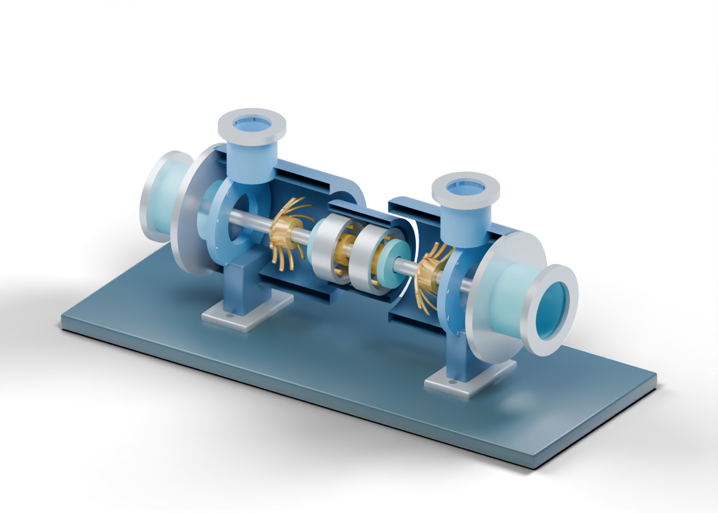
Turboexpander teaching display base
Studio support only; no skid, alignment or foundation design. Invented geometry and scale. No selected gas, inlet condition, expansion ratio, refrigeration duty, NGL yield, aerodynamic profile, speed, stress, bearing/seal design, pressure rating, control, protection, emissions or service qualification.
Complete expander casing wall
Hollow enclosure with one true upper entry opening. The internal path is not designed. Invented geometry and scale. No selected gas, inlet condition, expansion ratio, refrigeration duty, NGL yield, aerodynamic profile, speed, stress, bearing/seal design, pressure rating, control, protection, emissions or service qualification.
Complete loading-compressor casing wall
Hollow enclosure with one true upper exit opening. The internal path is not designed. Invented geometry and scale. No selected gas, inlet condition, expansion ratio, refrigeration duty, NGL yield, aerodynamic profile, speed, stress, bearing/seal design, pressure rating, control, protection, emissions or service qualification.
Open expander radial inlet neck
Gas entry boundary toward the expansion role. Invented geometry and scale. No selected gas, inlet condition, expansion ratio, refrigeration duty, NGL yield, aerodynamic profile, speed, stress, bearing/seal design, pressure rating, control, protection, emissions or service qualification.
Expander inlet open flange marker
Unrated entry joint location. Invented geometry and scale. No selected gas, inlet condition, expansion ratio, refrigeration duty, NGL yield, aerodynamic profile, speed, stress, bearing/seal design, pressure rating, control, protection, emissions or service qualification.
Open compressor radial discharge neck
Gas exit boundary from the loading-compressor role. Invented geometry and scale. No selected gas, inlet condition, expansion ratio, refrigeration duty, NGL yield, aerodynamic profile, speed, stress, bearing/seal design, pressure rating, control, protection, emissions or service qualification.
Compressor discharge open flange marker
Unrated exit joint location. Invented geometry and scale. No selected gas, inlet condition, expansion ratio, refrigeration duty, NGL yield, aerodynamic profile, speed, stress, bearing/seal design, pressure rating, control, protection, emissions or service qualification.
Expander outer end closure annulus
Axially open end marker; not a pressure-rated closure. Invented geometry and scale. No selected gas, inlet condition, expansion ratio, refrigeration duty, NGL yield, aerodynamic profile, speed, stress, bearing/seal design, pressure rating, control, protection, emissions or service qualification.
Open expander axial outlet neck
Separate open expander outlet boundary; no verified gas route. Invented geometry and scale. No selected gas, inlet condition, expansion ratio, refrigeration duty, NGL yield, aerodynamic profile, speed, stress, bearing/seal design, pressure rating, control, protection, emissions or service qualification.
Expander outlet open flange marker
Unrated open outlet joint marker. Invented geometry and scale. No selected gas, inlet condition, expansion ratio, refrigeration duty, NGL yield, aerodynamic profile, speed, stress, bearing/seal design, pressure rating, control, protection, emissions or service qualification.
Compressor outer end closure annulus
Axially open end marker; not a pressure-rated closure. Invented geometry and scale. No selected gas, inlet condition, expansion ratio, refrigeration duty, NGL yield, aerodynamic profile, speed, stress, bearing/seal design, pressure rating, control, protection, emissions or service qualification.
Open compressor axial suction neck
Separate open compressor-entry boundary; no verified gas route. Invented geometry and scale. No selected gas, inlet condition, expansion ratio, refrigeration duty, NGL yield, aerodynamic profile, speed, stress, bearing/seal design, pressure rating, control, protection, emissions or service qualification.
Compressor suction open flange marker
Unrated open suction joint marker. Invented geometry and scale. No selected gas, inlet condition, expansion ratio, refrigeration duty, NGL yield, aerodynamic profile, speed, stress, bearing/seal design, pressure rating, control, protection, emissions or service qualification.
Expander rotor hub
Rotating-region centre on the common shaft. Invented geometry and scale. No selected gas, inlet condition, expansion ratio, refrigeration duty, NGL yield, aerodynamic profile, speed, stress, bearing/seal design, pressure rating, control, protection, emissions or service qualification.
Expander inner wheel shroud
Independent annular wheel boundary, with invented clearance. Invented geometry and scale. No selected gas, inlet condition, expansion ratio, refrigeration duty, NGL yield, aerodynamic profile, speed, stress, bearing/seal design, pressure rating, control, protection, emissions or service qualification.
Expander outer wheel shroud
Independent annular wheel boundary, with invented clearance. Invented geometry and scale. No selected gas, inlet condition, expansion ratio, refrigeration duty, NGL yield, aerodynamic profile, speed, stress, bearing/seal design, pressure rating, control, protection, emissions or service qualification.
Expander swept wheel vane 1
Static wheel-vane cue; not a tested turbine or compressor aerodynamic profile. Invented geometry and scale. No selected gas, inlet condition, expansion ratio, refrigeration duty, NGL yield, aerodynamic profile, speed, stress, bearing/seal design, pressure rating, control, protection, emissions or service qualification.
Expander swept wheel vane 2
Static wheel-vane cue; not a tested turbine or compressor aerodynamic profile. Invented geometry and scale. No selected gas, inlet condition, expansion ratio, refrigeration duty, NGL yield, aerodynamic profile, speed, stress, bearing/seal design, pressure rating, control, protection, emissions or service qualification.
Expander swept wheel vane 3
Static wheel-vane cue; not a tested turbine or compressor aerodynamic profile. Invented geometry and scale. No selected gas, inlet condition, expansion ratio, refrigeration duty, NGL yield, aerodynamic profile, speed, stress, bearing/seal design, pressure rating, control, protection, emissions or service qualification.
Expander swept wheel vane 4
Static wheel-vane cue; not a tested turbine or compressor aerodynamic profile. Invented geometry and scale. No selected gas, inlet condition, expansion ratio, refrigeration duty, NGL yield, aerodynamic profile, speed, stress, bearing/seal design, pressure rating, control, protection, emissions or service qualification.
Expander swept wheel vane 5
Static wheel-vane cue; not a tested turbine or compressor aerodynamic profile. Invented geometry and scale. No selected gas, inlet condition, expansion ratio, refrigeration duty, NGL yield, aerodynamic profile, speed, stress, bearing/seal design, pressure rating, control, protection, emissions or service qualification.
Expander swept wheel vane 6
Static wheel-vane cue; not a tested turbine or compressor aerodynamic profile. Invented geometry and scale. No selected gas, inlet condition, expansion ratio, refrigeration duty, NGL yield, aerodynamic profile, speed, stress, bearing/seal design, pressure rating, control, protection, emissions or service qualification.
Expander swept wheel vane 7
Static wheel-vane cue; not a tested turbine or compressor aerodynamic profile. Invented geometry and scale. No selected gas, inlet condition, expansion ratio, refrigeration duty, NGL yield, aerodynamic profile, speed, stress, bearing/seal design, pressure rating, control, protection, emissions or service qualification.
Expander swept wheel vane 8
Static wheel-vane cue; not a tested turbine or compressor aerodynamic profile. Invented geometry and scale. No selected gas, inlet condition, expansion ratio, refrigeration duty, NGL yield, aerodynamic profile, speed, stress, bearing/seal design, pressure rating, control, protection, emissions or service qualification.
Expander swept wheel vane 9
Static wheel-vane cue; not a tested turbine or compressor aerodynamic profile. Invented geometry and scale. No selected gas, inlet condition, expansion ratio, refrigeration duty, NGL yield, aerodynamic profile, speed, stress, bearing/seal design, pressure rating, control, protection, emissions or service qualification.
Expander swept wheel vane 10
Static wheel-vane cue; not a tested turbine or compressor aerodynamic profile. Invented geometry and scale. No selected gas, inlet condition, expansion ratio, refrigeration duty, NGL yield, aerodynamic profile, speed, stress, bearing/seal design, pressure rating, control, protection, emissions or service qualification.
Expander swept wheel vane 11
Static wheel-vane cue; not a tested turbine or compressor aerodynamic profile. Invented geometry and scale. No selected gas, inlet condition, expansion ratio, refrigeration duty, NGL yield, aerodynamic profile, speed, stress, bearing/seal design, pressure rating, control, protection, emissions or service qualification.
Expander swept wheel vane 12
Static wheel-vane cue; not a tested turbine or compressor aerodynamic profile. Invented geometry and scale. No selected gas, inlet condition, expansion ratio, refrigeration duty, NGL yield, aerodynamic profile, speed, stress, bearing/seal design, pressure rating, control, protection, emissions or service qualification.
Loading compressor rotor hub
Rotating-region centre on the common shaft. Invented geometry and scale. No selected gas, inlet condition, expansion ratio, refrigeration duty, NGL yield, aerodynamic profile, speed, stress, bearing/seal design, pressure rating, control, protection, emissions or service qualification.
Loading compressor inner wheel shroud
Independent annular wheel boundary, with invented clearance. Invented geometry and scale. No selected gas, inlet condition, expansion ratio, refrigeration duty, NGL yield, aerodynamic profile, speed, stress, bearing/seal design, pressure rating, control, protection, emissions or service qualification.
Loading compressor outer wheel shroud
Independent annular wheel boundary, with invented clearance. Invented geometry and scale. No selected gas, inlet condition, expansion ratio, refrigeration duty, NGL yield, aerodynamic profile, speed, stress, bearing/seal design, pressure rating, control, protection, emissions or service qualification.
Loading compressor swept wheel vane 1
Static wheel-vane cue; not a tested turbine or compressor aerodynamic profile. Invented geometry and scale. No selected gas, inlet condition, expansion ratio, refrigeration duty, NGL yield, aerodynamic profile, speed, stress, bearing/seal design, pressure rating, control, protection, emissions or service qualification.
Loading compressor swept wheel vane 2
Static wheel-vane cue; not a tested turbine or compressor aerodynamic profile. Invented geometry and scale. No selected gas, inlet condition, expansion ratio, refrigeration duty, NGL yield, aerodynamic profile, speed, stress, bearing/seal design, pressure rating, control, protection, emissions or service qualification.
Loading compressor swept wheel vane 3
Static wheel-vane cue; not a tested turbine or compressor aerodynamic profile. Invented geometry and scale. No selected gas, inlet condition, expansion ratio, refrigeration duty, NGL yield, aerodynamic profile, speed, stress, bearing/seal design, pressure rating, control, protection, emissions or service qualification.
Loading compressor swept wheel vane 4
Static wheel-vane cue; not a tested turbine or compressor aerodynamic profile. Invented geometry and scale. No selected gas, inlet condition, expansion ratio, refrigeration duty, NGL yield, aerodynamic profile, speed, stress, bearing/seal design, pressure rating, control, protection, emissions or service qualification.
Loading compressor swept wheel vane 5
Static wheel-vane cue; not a tested turbine or compressor aerodynamic profile. Invented geometry and scale. No selected gas, inlet condition, expansion ratio, refrigeration duty, NGL yield, aerodynamic profile, speed, stress, bearing/seal design, pressure rating, control, protection, emissions or service qualification.
Loading compressor swept wheel vane 6
Static wheel-vane cue; not a tested turbine or compressor aerodynamic profile. Invented geometry and scale. No selected gas, inlet condition, expansion ratio, refrigeration duty, NGL yield, aerodynamic profile, speed, stress, bearing/seal design, pressure rating, control, protection, emissions or service qualification.
Loading compressor swept wheel vane 7
Static wheel-vane cue; not a tested turbine or compressor aerodynamic profile. Invented geometry and scale. No selected gas, inlet condition, expansion ratio, refrigeration duty, NGL yield, aerodynamic profile, speed, stress, bearing/seal design, pressure rating, control, protection, emissions or service qualification.
Loading compressor swept wheel vane 8
Static wheel-vane cue; not a tested turbine or compressor aerodynamic profile. Invented geometry and scale. No selected gas, inlet condition, expansion ratio, refrigeration duty, NGL yield, aerodynamic profile, speed, stress, bearing/seal design, pressure rating, control, protection, emissions or service qualification.
Loading compressor swept wheel vane 9
Static wheel-vane cue; not a tested turbine or compressor aerodynamic profile. Invented geometry and scale. No selected gas, inlet condition, expansion ratio, refrigeration duty, NGL yield, aerodynamic profile, speed, stress, bearing/seal design, pressure rating, control, protection, emissions or service qualification.
Loading compressor swept wheel vane 10
Static wheel-vane cue; not a tested turbine or compressor aerodynamic profile. Invented geometry and scale. No selected gas, inlet condition, expansion ratio, refrigeration duty, NGL yield, aerodynamic profile, speed, stress, bearing/seal design, pressure rating, control, protection, emissions or service qualification.
Loading compressor swept wheel vane 11
Static wheel-vane cue; not a tested turbine or compressor aerodynamic profile. Invented geometry and scale. No selected gas, inlet condition, expansion ratio, refrigeration duty, NGL yield, aerodynamic profile, speed, stress, bearing/seal design, pressure rating, control, protection, emissions or service qualification.
Loading compressor swept wheel vane 12
Static wheel-vane cue; not a tested turbine or compressor aerodynamic profile. Invented geometry and scale. No selected gas, inlet condition, expansion ratio, refrigeration duty, NGL yield, aerodynamic profile, speed, stress, bearing/seal design, pressure rating, control, protection, emissions or service qualification.
Expander stationary nozzle carrier
Distinct stationary inlet-guide region, without a designed nozzle throat or flow area. Invented geometry and scale. No selected gas, inlet condition, expansion ratio, refrigeration duty, NGL yield, aerodynamic profile, speed, stress, bearing/seal design, pressure rating, control, protection, emissions or service qualification.
Expander stationary guide vane 1
Stationary guide-region cue ahead of the expander wheel. Invented geometry and scale. No selected gas, inlet condition, expansion ratio, refrigeration duty, NGL yield, aerodynamic profile, speed, stress, bearing/seal design, pressure rating, control, protection, emissions or service qualification.
Expander stationary guide vane 2
Stationary guide-region cue ahead of the expander wheel. Invented geometry and scale. No selected gas, inlet condition, expansion ratio, refrigeration duty, NGL yield, aerodynamic profile, speed, stress, bearing/seal design, pressure rating, control, protection, emissions or service qualification.
Expander stationary guide vane 3
Stationary guide-region cue ahead of the expander wheel. Invented geometry and scale. No selected gas, inlet condition, expansion ratio, refrigeration duty, NGL yield, aerodynamic profile, speed, stress, bearing/seal design, pressure rating, control, protection, emissions or service qualification.
Expander stationary guide vane 4
Stationary guide-region cue ahead of the expander wheel. Invented geometry and scale. No selected gas, inlet condition, expansion ratio, refrigeration duty, NGL yield, aerodynamic profile, speed, stress, bearing/seal design, pressure rating, control, protection, emissions or service qualification.
Expander stationary guide vane 5
Stationary guide-region cue ahead of the expander wheel. Invented geometry and scale. No selected gas, inlet condition, expansion ratio, refrigeration duty, NGL yield, aerodynamic profile, speed, stress, bearing/seal design, pressure rating, control, protection, emissions or service qualification.
Expander stationary guide vane 6
Stationary guide-region cue ahead of the expander wheel. Invented geometry and scale. No selected gas, inlet condition, expansion ratio, refrigeration duty, NGL yield, aerodynamic profile, speed, stress, bearing/seal design, pressure rating, control, protection, emissions or service qualification.
Expander stationary guide vane 7
Stationary guide-region cue ahead of the expander wheel. Invented geometry and scale. No selected gas, inlet condition, expansion ratio, refrigeration duty, NGL yield, aerodynamic profile, speed, stress, bearing/seal design, pressure rating, control, protection, emissions or service qualification.
Expander stationary guide vane 8
Stationary guide-region cue ahead of the expander wheel. Invented geometry and scale. No selected gas, inlet condition, expansion ratio, refrigeration duty, NGL yield, aerodynamic profile, speed, stress, bearing/seal design, pressure rating, control, protection, emissions or service qualification.
Expander stationary guide vane 9
Stationary guide-region cue ahead of the expander wheel. Invented geometry and scale. No selected gas, inlet condition, expansion ratio, refrigeration duty, NGL yield, aerodynamic profile, speed, stress, bearing/seal design, pressure rating, control, protection, emissions or service qualification.
Expander stationary guide vane 10
Stationary guide-region cue ahead of the expander wheel. Invented geometry and scale. No selected gas, inlet condition, expansion ratio, refrigeration duty, NGL yield, aerodynamic profile, speed, stress, bearing/seal design, pressure rating, control, protection, emissions or service qualification.
Loading-compressor diffuser carrier
Separate stationary diffuser-region carrier, not a proven pressure-recovery passage. Invented geometry and scale. No selected gas, inlet condition, expansion ratio, refrigeration duty, NGL yield, aerodynamic profile, speed, stress, bearing/seal design, pressure rating, control, protection, emissions or service qualification.
Loading-compressor diffuser vane 1
Stationary diffuser-region cue after the wheel. Invented geometry and scale. No selected gas, inlet condition, expansion ratio, refrigeration duty, NGL yield, aerodynamic profile, speed, stress, bearing/seal design, pressure rating, control, protection, emissions or service qualification.
Loading-compressor diffuser vane 2
Stationary diffuser-region cue after the wheel. Invented geometry and scale. No selected gas, inlet condition, expansion ratio, refrigeration duty, NGL yield, aerodynamic profile, speed, stress, bearing/seal design, pressure rating, control, protection, emissions or service qualification.
Loading-compressor diffuser vane 3
Stationary diffuser-region cue after the wheel. Invented geometry and scale. No selected gas, inlet condition, expansion ratio, refrigeration duty, NGL yield, aerodynamic profile, speed, stress, bearing/seal design, pressure rating, control, protection, emissions or service qualification.
Loading-compressor diffuser vane 4
Stationary diffuser-region cue after the wheel. Invented geometry and scale. No selected gas, inlet condition, expansion ratio, refrigeration duty, NGL yield, aerodynamic profile, speed, stress, bearing/seal design, pressure rating, control, protection, emissions or service qualification.
Loading-compressor diffuser vane 5
Stationary diffuser-region cue after the wheel. Invented geometry and scale. No selected gas, inlet condition, expansion ratio, refrigeration duty, NGL yield, aerodynamic profile, speed, stress, bearing/seal design, pressure rating, control, protection, emissions or service qualification.
Loading-compressor diffuser vane 6
Stationary diffuser-region cue after the wheel. Invented geometry and scale. No selected gas, inlet condition, expansion ratio, refrigeration duty, NGL yield, aerodynamic profile, speed, stress, bearing/seal design, pressure rating, control, protection, emissions or service qualification.
Loading-compressor diffuser vane 7
Stationary diffuser-region cue after the wheel. Invented geometry and scale. No selected gas, inlet condition, expansion ratio, refrigeration duty, NGL yield, aerodynamic profile, speed, stress, bearing/seal design, pressure rating, control, protection, emissions or service qualification.
Loading-compressor diffuser vane 8
Stationary diffuser-region cue after the wheel. Invented geometry and scale. No selected gas, inlet condition, expansion ratio, refrigeration duty, NGL yield, aerodynamic profile, speed, stress, bearing/seal design, pressure rating, control, protection, emissions or service qualification.
Loading-compressor diffuser vane 9
Stationary diffuser-region cue after the wheel. Invented geometry and scale. No selected gas, inlet condition, expansion ratio, refrigeration duty, NGL yield, aerodynamic profile, speed, stress, bearing/seal design, pressure rating, control, protection, emissions or service qualification.
Loading-compressor diffuser vane 10
Stationary diffuser-region cue after the wheel. Invented geometry and scale. No selected gas, inlet condition, expansion ratio, refrigeration duty, NGL yield, aerodynamic profile, speed, stress, bearing/seal design, pressure rating, control, protection, emissions or service qualification.
Common static expander-compressor shaft
One shaft connects the two wheel roles; no speed, work transfer, critical-speed or stress result is established. Invented geometry and scale. No selected gas, inlet condition, expansion ratio, refrigeration duty, NGL yield, aerodynamic profile, speed, stress, bearing/seal design, pressure rating, control, protection, emissions or service qualification.
Complete central bearing enclosure wall
Distinct shaft-support enclosure, not a lubrication package. Invented geometry and scale. No selected gas, inlet condition, expansion ratio, refrigeration duty, NGL yield, aerodynamic profile, speed, stress, bearing/seal design, pressure rating, control, protection, emissions or service qualification.
Expander side journal sleeve location
Static journal location; no bearing selection or film. Invented geometry and scale. No selected gas, inlet condition, expansion ratio, refrigeration duty, NGL yield, aerodynamic profile, speed, stress, bearing/seal design, pressure rating, control, protection, emissions or service qualification.
Expander side bearing carrier
Support-region carrier, with a true central opening. Invented geometry and scale. No selected gas, inlet condition, expansion ratio, refrigeration duty, NGL yield, aerodynamic profile, speed, stress, bearing/seal design, pressure rating, control, protection, emissions or service qualification.
Expander side bearing pad cue 1
Static bearing-pad position; no selected technology, clearance, load or lubricant. Invented geometry and scale. No selected gas, inlet condition, expansion ratio, refrigeration duty, NGL yield, aerodynamic profile, speed, stress, bearing/seal design, pressure rating, control, protection, emissions or service qualification.
Expander side bearing pad cue 2
Static bearing-pad position; no selected technology, clearance, load or lubricant. Invented geometry and scale. No selected gas, inlet condition, expansion ratio, refrigeration duty, NGL yield, aerodynamic profile, speed, stress, bearing/seal design, pressure rating, control, protection, emissions or service qualification.
Expander side bearing pad cue 3
Static bearing-pad position; no selected technology, clearance, load or lubricant. Invented geometry and scale. No selected gas, inlet condition, expansion ratio, refrigeration duty, NGL yield, aerodynamic profile, speed, stress, bearing/seal design, pressure rating, control, protection, emissions or service qualification.
Expander side bearing pad cue 4
Static bearing-pad position; no selected technology, clearance, load or lubricant. Invented geometry and scale. No selected gas, inlet condition, expansion ratio, refrigeration duty, NGL yield, aerodynamic profile, speed, stress, bearing/seal design, pressure rating, control, protection, emissions or service qualification.
Expander side bearing pad cue 5
Static bearing-pad position; no selected technology, clearance, load or lubricant. Invented geometry and scale. No selected gas, inlet condition, expansion ratio, refrigeration duty, NGL yield, aerodynamic profile, speed, stress, bearing/seal design, pressure rating, control, protection, emissions or service qualification.
Expander side bearing pad cue 6
Static bearing-pad position; no selected technology, clearance, load or lubricant. Invented geometry and scale. No selected gas, inlet condition, expansion ratio, refrigeration duty, NGL yield, aerodynamic profile, speed, stress, bearing/seal design, pressure rating, control, protection, emissions or service qualification.
Compressor side journal sleeve location
Static journal location; no bearing selection or film. Invented geometry and scale. No selected gas, inlet condition, expansion ratio, refrigeration duty, NGL yield, aerodynamic profile, speed, stress, bearing/seal design, pressure rating, control, protection, emissions or service qualification.
Compressor side bearing carrier
Support-region carrier, with a true central opening. Invented geometry and scale. No selected gas, inlet condition, expansion ratio, refrigeration duty, NGL yield, aerodynamic profile, speed, stress, bearing/seal design, pressure rating, control, protection, emissions or service qualification.
Compressor side bearing pad cue 1
Static bearing-pad position; no selected technology, clearance, load or lubricant. Invented geometry and scale. No selected gas, inlet condition, expansion ratio, refrigeration duty, NGL yield, aerodynamic profile, speed, stress, bearing/seal design, pressure rating, control, protection, emissions or service qualification.
Compressor side bearing pad cue 2
Static bearing-pad position; no selected technology, clearance, load or lubricant. Invented geometry and scale. No selected gas, inlet condition, expansion ratio, refrigeration duty, NGL yield, aerodynamic profile, speed, stress, bearing/seal design, pressure rating, control, protection, emissions or service qualification.
Compressor side bearing pad cue 3
Static bearing-pad position; no selected technology, clearance, load or lubricant. Invented geometry and scale. No selected gas, inlet condition, expansion ratio, refrigeration duty, NGL yield, aerodynamic profile, speed, stress, bearing/seal design, pressure rating, control, protection, emissions or service qualification.
Compressor side bearing pad cue 4
Static bearing-pad position; no selected technology, clearance, load or lubricant. Invented geometry and scale. No selected gas, inlet condition, expansion ratio, refrigeration duty, NGL yield, aerodynamic profile, speed, stress, bearing/seal design, pressure rating, control, protection, emissions or service qualification.
Compressor side bearing pad cue 5
Static bearing-pad position; no selected technology, clearance, load or lubricant. Invented geometry and scale. No selected gas, inlet condition, expansion ratio, refrigeration duty, NGL yield, aerodynamic profile, speed, stress, bearing/seal design, pressure rating, control, protection, emissions or service qualification.
Compressor side bearing pad cue 6
Static bearing-pad position; no selected technology, clearance, load or lubricant. Invented geometry and scale. No selected gas, inlet condition, expansion ratio, refrigeration duty, NGL yield, aerodynamic profile, speed, stress, bearing/seal design, pressure rating, control, protection, emissions or service qualification.
Expander process seal location
Seal-region marker only; no seal faces, gas support, leakage or emissions result. Invented geometry and scale. No selected gas, inlet condition, expansion ratio, refrigeration duty, NGL yield, aerodynamic profile, speed, stress, bearing/seal design, pressure rating, control, protection, emissions or service qualification.
Compressor process seal location
Seal-region marker only; no seal faces, gas support, leakage or emissions result. Invented geometry and scale. No selected gas, inlet condition, expansion ratio, refrigeration duty, NGL yield, aerodynamic profile, speed, stress, bearing/seal design, pressure rating, control, protection, emissions or service qualification.
Turboexpander display pedestal 1
Studio support, not a casing mount. Invented geometry and scale. No selected gas, inlet condition, expansion ratio, refrigeration duty, NGL yield, aerodynamic profile, speed, stress, bearing/seal design, pressure rating, control, protection, emissions or service qualification.
Bored turboexpander display foot 1
Illustrative drilled foot; no anchor or structural design. Invented geometry and scale. No selected gas, inlet condition, expansion ratio, refrigeration duty, NGL yield, aerodynamic profile, speed, stress, bearing/seal design, pressure rating, control, protection, emissions or service qualification.
Turboexpander display pedestal 2
Studio support, not a casing mount. Invented geometry and scale. No selected gas, inlet condition, expansion ratio, refrigeration duty, NGL yield, aerodynamic profile, speed, stress, bearing/seal design, pressure rating, control, protection, emissions or service qualification.
Bored turboexpander display foot 2
Illustrative drilled foot; no anchor or structural design. Invented geometry and scale. No selected gas, inlet condition, expansion ratio, refrigeration duty, NGL yield, aerodynamic profile, speed, stress, bearing/seal design, pressure rating, control, protection, emissions or service qualification.