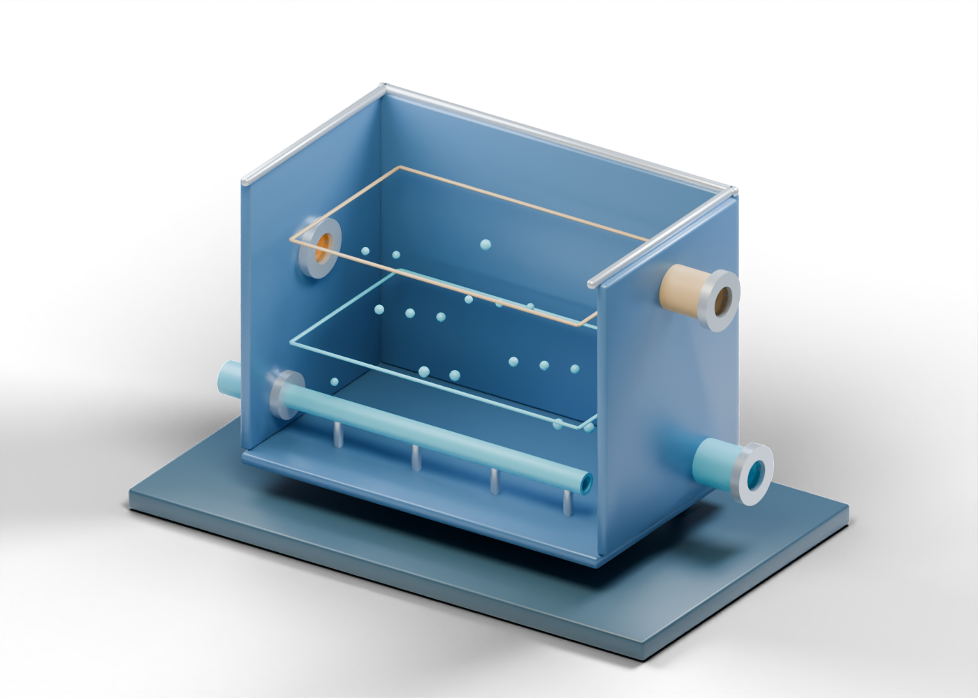
Base frame
Illustrative support frame; foundations and structural design vary.
Complete flotation-cell floor
Complete solid bottom separates the illustration from its display supports. Invented static teaching geometry; no operator configuration, air rate, recovery result, pressure rating, mass balance or operating instruction.
Complete front flotation-cell wall
Full outside and inside facing wall; the viewer initially hides it for reading and can restore it. Invented static teaching geometry; no operator configuration, air rate, recovery result, pressure rating, mass balance or operating instruction.
Complete back flotation-cell wall
Full rear wall; this rectangular form is an invented presentation choice. Invented static teaching geometry; no operator configuration, air rate, recovery result, pressure rating, mass balance or operating instruction.
Complete bored feed-and-air wall
Full side wall with two real, separate openings for middlings and air. Invented static teaching geometry; no operator configuration, air rate, recovery result, pressure rating, mass balance or operating instruction.
Complete bored product-and-residual wall
Full side wall with two real, separate openings for froth and remaining slurry. Invented static teaching geometry; no operator configuration, air rate, recovery result, pressure rating, mass balance or operating instruction.
Open middlings-feed connection
Hollow boundary for middlings arriving from a primary cell; upstream pumping is outside this lesson. Invented static teaching geometry; no operator configuration, air rate, recovery result, pressure rating, mass balance or operating instruction.
Open middlings-feed connection end collar
Unrated open-end connection marker. Invented static teaching geometry; no operator configuration, air rate, recovery result, pressure rating, mass balance or operating instruction.
Open air-addition connection
Separate hollow air-addition boundary. This is not a selected air supply or distribution design. Invented static teaching geometry; no operator configuration, air rate, recovery result, pressure rating, mass balance or operating instruction.
Open air-addition connection end collar
Unrated open-end connection marker. Invented static teaching geometry; no operator configuration, air rate, recovery result, pressure rating, mass balance or operating instruction.
Open secondary-froth outlet
Upper hollow boundary for additional bitumen froth toward further handling or return. Invented static teaching geometry; no operator configuration, air rate, recovery result, pressure rating, mass balance or operating instruction.
Open secondary-froth outlet end collar
Unrated open-end connection marker. Invented static teaching geometry; no operator configuration, air rate, recovery result, pressure rating, mass balance or operating instruction.
Open remaining-slurry outlet
Lower hollow boundary for water, solids and unrecovered bitumen before further treatment. Invented static teaching geometry; no operator configuration, air rate, recovery result, pressure rating, mass balance or operating instruction.
Open remaining-slurry outlet end collar
Unrated open-end connection marker. Invented static teaching geometry; no operator configuration, air rate, recovery result, pressure rating, mass balance or operating instruction.
Open illustrative air lance
One open-ended hollow line illustrates where air could enter the cell. It is not a sparger specification. Invented static teaching geometry; no operator configuration, air rate, recovery result, pressure rating, mass balance or operating instruction.
Air-lance support marker 1
Simple static support marker for the illustrative lance. Invented static teaching geometry; no operator configuration, air rate, recovery result, pressure rating, mass balance or operating instruction.
Air-lance support marker 2
Simple static support marker for the illustrative lance. Invented static teaching geometry; no operator configuration, air rate, recovery result, pressure rating, mass balance or operating instruction.
Air-lance support marker 3
Simple static support marker for the illustrative lance. Invented static teaching geometry; no operator configuration, air rate, recovery result, pressure rating, mass balance or operating instruction.
Air-lance support marker 4
Simple static support marker for the illustrative lance. Invented static teaching geometry; no operator configuration, air rate, recovery result, pressure rating, mass balance or operating instruction.
Static froth region edge 1
Fixed coloured reading boundary; not a measured phase interface or flow result. Invented static teaching geometry; no operator configuration, air rate, recovery result, pressure rating, mass balance or operating instruction.
Static froth region edge 2
Fixed coloured reading boundary; not a measured phase interface or flow result. Invented static teaching geometry; no operator configuration, air rate, recovery result, pressure rating, mass balance or operating instruction.
Static froth region edge 3
Fixed coloured reading boundary; not a measured phase interface or flow result. Invented static teaching geometry; no operator configuration, air rate, recovery result, pressure rating, mass balance or operating instruction.
Static froth region edge 4
Fixed coloured reading boundary; not a measured phase interface or flow result. Invented static teaching geometry; no operator configuration, air rate, recovery result, pressure rating, mass balance or operating instruction.
Static middlings region edge 1
Fixed coloured reading boundary; not a measured phase interface or flow result. Invented static teaching geometry; no operator configuration, air rate, recovery result, pressure rating, mass balance or operating instruction.
Static middlings region edge 2
Fixed coloured reading boundary; not a measured phase interface or flow result. Invented static teaching geometry; no operator configuration, air rate, recovery result, pressure rating, mass balance or operating instruction.
Static middlings region edge 3
Fixed coloured reading boundary; not a measured phase interface or flow result. Invented static teaching geometry; no operator configuration, air rate, recovery result, pressure rating, mass balance or operating instruction.
Static middlings region edge 4
Fixed coloured reading boundary; not a measured phase interface or flow result. Invented static teaching geometry; no operator configuration, air rate, recovery result, pressure rating, mass balance or operating instruction.
Static air bubble marker 1
A fixed visual cue for introduced air, not measured bubbles or simulated flotation. Invented static teaching geometry; no operator configuration, air rate, recovery result, pressure rating, mass balance or operating instruction.
Static air bubble marker 2
A fixed visual cue for introduced air, not measured bubbles or simulated flotation. Invented static teaching geometry; no operator configuration, air rate, recovery result, pressure rating, mass balance or operating instruction.
Static air bubble marker 3
A fixed visual cue for introduced air, not measured bubbles or simulated flotation. Invented static teaching geometry; no operator configuration, air rate, recovery result, pressure rating, mass balance or operating instruction.
Static air bubble marker 4
A fixed visual cue for introduced air, not measured bubbles or simulated flotation. Invented static teaching geometry; no operator configuration, air rate, recovery result, pressure rating, mass balance or operating instruction.
Static air bubble marker 5
A fixed visual cue for introduced air, not measured bubbles or simulated flotation. Invented static teaching geometry; no operator configuration, air rate, recovery result, pressure rating, mass balance or operating instruction.
Static air bubble marker 6
A fixed visual cue for introduced air, not measured bubbles or simulated flotation. Invented static teaching geometry; no operator configuration, air rate, recovery result, pressure rating, mass balance or operating instruction.
Static air bubble marker 7
A fixed visual cue for introduced air, not measured bubbles or simulated flotation. Invented static teaching geometry; no operator configuration, air rate, recovery result, pressure rating, mass balance or operating instruction.
Static air bubble marker 8
A fixed visual cue for introduced air, not measured bubbles or simulated flotation. Invented static teaching geometry; no operator configuration, air rate, recovery result, pressure rating, mass balance or operating instruction.
Static air bubble marker 9
A fixed visual cue for introduced air, not measured bubbles or simulated flotation. Invented static teaching geometry; no operator configuration, air rate, recovery result, pressure rating, mass balance or operating instruction.
Static air bubble marker 10
A fixed visual cue for introduced air, not measured bubbles or simulated flotation. Invented static teaching geometry; no operator configuration, air rate, recovery result, pressure rating, mass balance or operating instruction.
Static air bubble marker 11
A fixed visual cue for introduced air, not measured bubbles or simulated flotation. Invented static teaching geometry; no operator configuration, air rate, recovery result, pressure rating, mass balance or operating instruction.
Static air bubble marker 12
A fixed visual cue for introduced air, not measured bubbles or simulated flotation. Invented static teaching geometry; no operator configuration, air rate, recovery result, pressure rating, mass balance or operating instruction.
Static air bubble marker 13
A fixed visual cue for introduced air, not measured bubbles or simulated flotation. Invented static teaching geometry; no operator configuration, air rate, recovery result, pressure rating, mass balance or operating instruction.
Static air bubble marker 14
A fixed visual cue for introduced air, not measured bubbles or simulated flotation. Invented static teaching geometry; no operator configuration, air rate, recovery result, pressure rating, mass balance or operating instruction.
Static air bubble marker 15
A fixed visual cue for introduced air, not measured bubbles or simulated flotation. Invented static teaching geometry; no operator configuration, air rate, recovery result, pressure rating, mass balance or operating instruction.
Static air bubble marker 16
A fixed visual cue for introduced air, not measured bubbles or simulated flotation. Invented static teaching geometry; no operator configuration, air rate, recovery result, pressure rating, mass balance or operating instruction.
Static air bubble marker 17
A fixed visual cue for introduced air, not measured bubbles or simulated flotation. Invented static teaching geometry; no operator configuration, air rate, recovery result, pressure rating, mass balance or operating instruction.
Static air bubble marker 18
A fixed visual cue for introduced air, not measured bubbles or simulated flotation. Invented static teaching geometry; no operator configuration, air rate, recovery result, pressure rating, mass balance or operating instruction.
Upper long rim rail 1
Open-top perimeter marker without access or containment qualification. Invented static teaching geometry; no operator configuration, air rate, recovery result, pressure rating, mass balance or operating instruction.
Upper long rim rail 2
Open-top perimeter marker without access or containment qualification. Invented static teaching geometry; no operator configuration, air rate, recovery result, pressure rating, mass balance or operating instruction.
Upper cross rim rail 1
Open-top perimeter marker without access or containment qualification. Invented static teaching geometry; no operator configuration, air rate, recovery result, pressure rating, mass balance or operating instruction.
Upper cross rim rail 2
Open-top perimeter marker without access or containment qualification. Invented static teaching geometry; no operator configuration, air rate, recovery result, pressure rating, mass balance or operating instruction.
Display support 1
Presentation support only, not a plant foundation or structural design. Invented static teaching geometry; no operator configuration, air rate, recovery result, pressure rating, mass balance or operating instruction.
Display foot 1
Illustrative display foot, not a plant anchor. Invented static teaching geometry; no operator configuration, air rate, recovery result, pressure rating, mass balance or operating instruction.
Display support 2
Presentation support only, not a plant foundation or structural design. Invented static teaching geometry; no operator configuration, air rate, recovery result, pressure rating, mass balance or operating instruction.
Display foot 2
Illustrative display foot, not a plant anchor. Invented static teaching geometry; no operator configuration, air rate, recovery result, pressure rating, mass balance or operating instruction.
Display support 3
Presentation support only, not a plant foundation or structural design. Invented static teaching geometry; no operator configuration, air rate, recovery result, pressure rating, mass balance or operating instruction.
Display foot 3
Illustrative display foot, not a plant anchor. Invented static teaching geometry; no operator configuration, air rate, recovery result, pressure rating, mass balance or operating instruction.
Display support 4
Presentation support only, not a plant foundation or structural design. Invented static teaching geometry; no operator configuration, air rate, recovery result, pressure rating, mass balance or operating instruction.
Display foot 4
Illustrative display foot, not a plant anchor. Invented static teaching geometry; no operator configuration, air rate, recovery result, pressure rating, mass balance or operating instruction.