Display plinth
Presentation base, not an installed foundation. Original generic static geometry: no selected vessel, pressure rating, level setpoint, separation efficiency, fluid condition, control system, downstream treatment or service qualification.
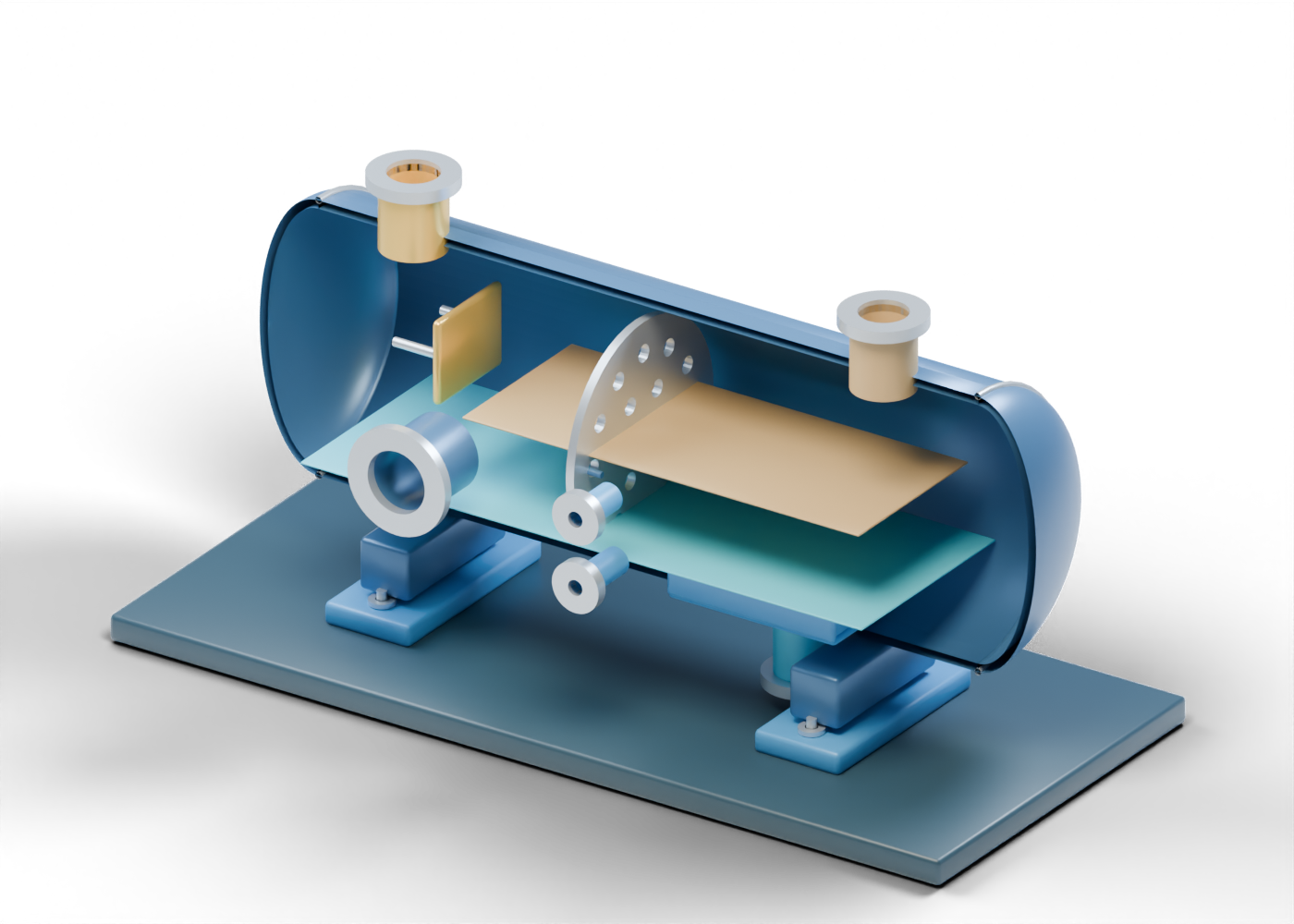
FWKO hollow vessel wall
Complete double-surface horizontal enclosure with real selected side openings. Original generic static geometry: no selected vessel, pressure rating, level setpoint, separation efficiency, fluid condition, control system, downstream treatment or service qualification.
Dished end -1
Generic double-surface dished closure. Shape and thickness are illustrative, with no code qualification.
End seam marker -1
Visible junction only; no weld or code-head specification. Original generic static geometry: no selected vessel, pressure rating, level setpoint, separation efficiency, fluid condition, control system, downstream treatment or service qualification.
Dished end 1
Generic double-surface dished closure. Shape and thickness are illustrative, with no code qualification.
End seam marker 1
Visible junction only; no weld or code-head specification. Original generic static geometry: no selected vessel, pressure rating, level setpoint, separation efficiency, fluid condition, control system, downstream treatment or service qualification.
Mixed feed hollow neck
Open connection at a real wall opening; destination and rating are not selected. Original generic static geometry: no selected vessel, pressure rating, level setpoint, separation efficiency, fluid condition, control system, downstream treatment or service qualification.
Mixed feed open collar
Separate open collar; no gasket, bolt or mating-pipe qualification. Original generic static geometry: no selected vessel, pressure rating, level setpoint, separation efficiency, fluid condition, control system, downstream treatment or service qualification.
Oil-and-gas emulsion exit hollow neck
Open connection at a real wall opening; destination and rating are not selected. Original generic static geometry: no selected vessel, pressure rating, level setpoint, separation efficiency, fluid condition, control system, downstream treatment or service qualification.
Oil-and-gas emulsion exit open collar
Separate open collar; no gasket, bolt or mating-pipe qualification. Original generic static geometry: no selected vessel, pressure rating, level setpoint, separation efficiency, fluid condition, control system, downstream treatment or service qualification.
Separate free-water draw hollow neck
Open connection at a real wall opening; destination and rating are not selected. Original generic static geometry: no selected vessel, pressure rating, level setpoint, separation efficiency, fluid condition, control system, downstream treatment or service qualification.
Separate free-water draw open collar
Separate open collar; no gasket, bolt or mating-pipe qualification. Original generic static geometry: no selected vessel, pressure rating, level setpoint, separation efficiency, fluid condition, control system, downstream treatment or service qualification.
Lower interface boundary hollow neck
Open connection at a real wall opening; destination and rating are not selected. Original generic static geometry: no selected vessel, pressure rating, level setpoint, separation efficiency, fluid condition, control system, downstream treatment or service qualification.
Lower interface boundary open collar
Separate open collar; no gasket, bolt or mating-pipe qualification. Original generic static geometry: no selected vessel, pressure rating, level setpoint, separation efficiency, fluid condition, control system, downstream treatment or service qualification.
Upper liquid boundary hollow neck
Open connection at a real wall opening; destination and rating are not selected. Original generic static geometry: no selected vessel, pressure rating, level setpoint, separation efficiency, fluid condition, control system, downstream treatment or service qualification.
Upper liquid boundary open collar
Separate open collar; no gasket, bolt or mating-pipe qualification. Original generic static geometry: no selected vessel, pressure rating, level setpoint, separation efficiency, fluid condition, control system, downstream treatment or service qualification.
Separate inlet impact plate
Invented diverter-position plate, not a selected impact device. Original generic static geometry: no selected vessel, pressure rating, level setpoint, separation efficiency, fluid condition, control system, downstream treatment or service qualification.
Diverter standoff 1
Independent support marker; no attachment or load design. Original generic static geometry: no selected vessel, pressure rating, level setpoint, separation efficiency, fluid condition, control system, downstream treatment or service qualification.
Diverter standoff 2
Independent support marker; no attachment or load design. Original generic static geometry: no selected vessel, pressure rating, level setpoint, separation efficiency, fluid condition, control system, downstream treatment or service qualification.
Quieting baffle with actual openings
Invented perforated plate location. Hole count and spacing are not selected design values. Original generic static geometry: no selected vessel, pressure rating, level setpoint, separation efficiency, fluid condition, control system, downstream treatment or service qualification.
Baffle support tie -0.67
Illustrative plate-location support, without weld or strength design. Original generic static geometry: no selected vessel, pressure rating, level setpoint, separation efficiency, fluid condition, control system, downstream treatment or service qualification.
Baffle support tie 0.67
Illustrative plate-location support, without weld or strength design. Original generic static geometry: no selected vessel, pressure rating, level setpoint, separation efficiency, fluid condition, control system, downstream treatment or service qualification.
Static free-water boundary plane
Arbitrary blue reading plane, not a measured interface or separated volume. Original generic static geometry: no selected vessel, pressure rating, level setpoint, separation efficiency, fluid condition, control system, downstream treatment or service qualification.
Static emulsion region marker
Arbitrary upper liquid marker; no product quality or oil level result. Original generic static geometry: no selected vessel, pressure rating, level setpoint, separation efficiency, fluid condition, control system, downstream treatment or service qualification.
Water-pocket floor marker
Open-spaced lower collection-location marker; no seal or hydraulic result. Original generic static geometry: no selected vessel, pressure rating, level setpoint, separation efficiency, fluid condition, control system, downstream treatment or service qualification.
Water-pocket far rail
Open-spaced lower collection-location marker; no seal or hydraulic result. Original generic static geometry: no selected vessel, pressure rating, level setpoint, separation efficiency, fluid condition, control system, downstream treatment or service qualification.
Water-pocket near rail
Open-spaced lower collection-location marker; no seal or hydraulic result. Original generic static geometry: no selected vessel, pressure rating, level setpoint, separation efficiency, fluid condition, control system, downstream treatment or service qualification.
Water-pocket end marker
Open-spaced lower collection-location marker; no seal or hydraulic result. Original generic static geometry: no selected vessel, pressure rating, level setpoint, separation efficiency, fluid condition, control system, downstream treatment or service qualification.
Inspection neck
Bored inspection location with a separate closed cover. Original generic static geometry: no selected vessel, pressure rating, level setpoint, separation efficiency, fluid condition, control system, downstream treatment or service qualification.
Inspection cover seat
Annular cover position; no gasket or pressure rating. Original generic static geometry: no selected vessel, pressure rating, level setpoint, separation efficiency, fluid condition, control system, downstream treatment or service qualification.
Closed inspection cover
Separate solid cover in a closed pose. No vessel-entry procedure. Original generic static geometry: no selected vessel, pressure rating, level setpoint, separation efficiency, fluid condition, control system, downstream treatment or service qualification.
Saddle support -1.76
Static support location; no structural or foundation design. Original generic static geometry: no selected vessel, pressure rating, level setpoint, separation efficiency, fluid condition, control system, downstream treatment or service qualification.
Bored saddle foot -1.76
Separate base plate with actual anchor openings. Original generic static geometry: no selected vessel, pressure rating, level setpoint, separation efficiency, fluid condition, control system, downstream treatment or service qualification.
Smooth anchor marker -1.76 1
Unthreaded location marker through an open foot hole. Original generic static geometry: no selected vessel, pressure rating, level setpoint, separation efficiency, fluid condition, control system, downstream treatment or service qualification.
Anchor washer -1.76 1
Separate annular washer marker; no retention or preload design. Original generic static geometry: no selected vessel, pressure rating, level setpoint, separation efficiency, fluid condition, control system, downstream treatment or service qualification.
Smooth anchor marker -1.76 2
Unthreaded location marker through an open foot hole. Original generic static geometry: no selected vessel, pressure rating, level setpoint, separation efficiency, fluid condition, control system, downstream treatment or service qualification.
Anchor washer -1.76 2
Separate annular washer marker; no retention or preload design. Original generic static geometry: no selected vessel, pressure rating, level setpoint, separation efficiency, fluid condition, control system, downstream treatment or service qualification.
Saddle support 1.76
Static support location; no structural or foundation design. Original generic static geometry: no selected vessel, pressure rating, level setpoint, separation efficiency, fluid condition, control system, downstream treatment or service qualification.
Bored saddle foot 1.76
Separate base plate with actual anchor openings. Original generic static geometry: no selected vessel, pressure rating, level setpoint, separation efficiency, fluid condition, control system, downstream treatment or service qualification.
Smooth anchor marker 1.76 1
Unthreaded location marker through an open foot hole. Original generic static geometry: no selected vessel, pressure rating, level setpoint, separation efficiency, fluid condition, control system, downstream treatment or service qualification.
Anchor washer 1.76 1
Separate annular washer marker; no retention or preload design. Original generic static geometry: no selected vessel, pressure rating, level setpoint, separation efficiency, fluid condition, control system, downstream treatment or service qualification.
Smooth anchor marker 1.76 2
Unthreaded location marker through an open foot hole. Original generic static geometry: no selected vessel, pressure rating, level setpoint, separation efficiency, fluid condition, control system, downstream treatment or service qualification.
Anchor washer 1.76 2
Separate annular washer marker; no retention or preload design. Original generic static geometry: no selected vessel, pressure rating, level setpoint, separation efficiency, fluid condition, control system, downstream treatment or service qualification.