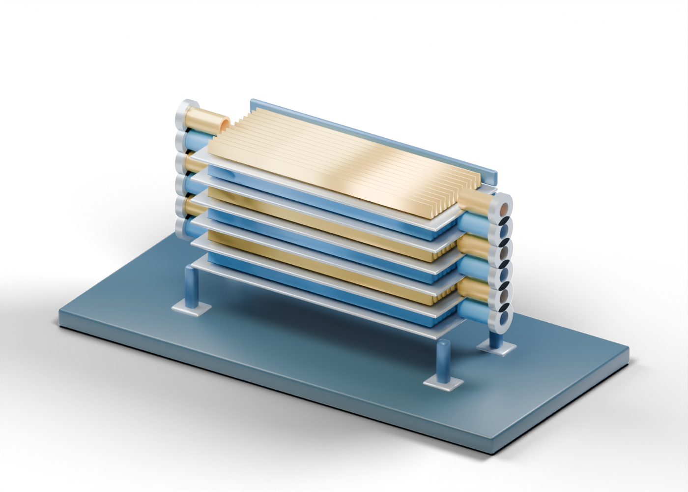
Base frame
Illustrative support frame; foundations and structural design vary.
Parting sheet 1
Separate layer boundary; not a fabricated brazed sheet. Original invented teaching dimensions and layer assignment. No selected fluid, service, metallurgy, brazed joint, pressure boundary, heat-transfer area, duty, temperature approach, pressure drop, thermal stress or operating procedure.
Parting sheet 2
Separate layer boundary; not a fabricated brazed sheet. Original invented teaching dimensions and layer assignment. No selected fluid, service, metallurgy, brazed joint, pressure boundary, heat-transfer area, duty, temperature approach, pressure drop, thermal stress or operating procedure.
Parting sheet 3
Separate layer boundary; not a fabricated brazed sheet. Original invented teaching dimensions and layer assignment. No selected fluid, service, metallurgy, brazed joint, pressure boundary, heat-transfer area, duty, temperature approach, pressure drop, thermal stress or operating procedure.
Parting sheet 4
Separate layer boundary; not a fabricated brazed sheet. Original invented teaching dimensions and layer assignment. No selected fluid, service, metallurgy, brazed joint, pressure boundary, heat-transfer area, duty, temperature approach, pressure drop, thermal stress or operating procedure.
Parting sheet 5
Separate layer boundary; not a fabricated brazed sheet. Original invented teaching dimensions and layer assignment. No selected fluid, service, metallurgy, brazed joint, pressure boundary, heat-transfer area, duty, temperature approach, pressure drop, thermal stress or operating procedure.
Parting sheet 6
Separate layer boundary; not a fabricated brazed sheet. Original invented teaching dimensions and layer assignment. No selected fluid, service, metallurgy, brazed joint, pressure boundary, heat-transfer area, duty, temperature approach, pressure drop, thermal stress or operating procedure.
Parting sheet 7
Separate layer boundary; not a fabricated brazed sheet. Original invented teaching dimensions and layer assignment. No selected fluid, service, metallurgy, brazed joint, pressure boundary, heat-transfer area, duty, temperature approach, pressure drop, thermal stress or operating procedure.
Layer 1 front side-bar
Separate side closure of illustrative stream A gap. Not a verified seal or brazed joint. Original invented teaching dimensions and layer assignment. No selected fluid, service, metallurgy, brazed joint, pressure boundary, heat-transfer area, duty, temperature approach, pressure drop, thermal stress or operating procedure.
Layer 1 rear side-bar
Separate side closure of illustrative stream A gap. Not a verified seal or brazed joint. Original invented teaching dimensions and layer assignment. No selected fluid, service, metallurgy, brazed joint, pressure boundary, heat-transfer area, duty, temperature approach, pressure drop, thermal stress or operating procedure.
Layer 1 stream A corrugated fin 1
One separately inspectable V fin in illustrative stream A layer. Open gaps between fins are real, but fin pitch, profile and flow are not designed. Original invented teaching dimensions and layer assignment. No selected fluid, service, metallurgy, brazed joint, pressure boundary, heat-transfer area, duty, temperature approach, pressure drop, thermal stress or operating procedure.
Layer 1 stream A corrugated fin 2
One separately inspectable V fin in illustrative stream A layer. Open gaps between fins are real, but fin pitch, profile and flow are not designed. Original invented teaching dimensions and layer assignment. No selected fluid, service, metallurgy, brazed joint, pressure boundary, heat-transfer area, duty, temperature approach, pressure drop, thermal stress or operating procedure.
Layer 1 stream A corrugated fin 3
One separately inspectable V fin in illustrative stream A layer. Open gaps between fins are real, but fin pitch, profile and flow are not designed. Original invented teaching dimensions and layer assignment. No selected fluid, service, metallurgy, brazed joint, pressure boundary, heat-transfer area, duty, temperature approach, pressure drop, thermal stress or operating procedure.
Layer 1 stream A corrugated fin 4
One separately inspectable V fin in illustrative stream A layer. Open gaps between fins are real, but fin pitch, profile and flow are not designed. Original invented teaching dimensions and layer assignment. No selected fluid, service, metallurgy, brazed joint, pressure boundary, heat-transfer area, duty, temperature approach, pressure drop, thermal stress or operating procedure.
Layer 1 stream A corrugated fin 5
One separately inspectable V fin in illustrative stream A layer. Open gaps between fins are real, but fin pitch, profile and flow are not designed. Original invented teaching dimensions and layer assignment. No selected fluid, service, metallurgy, brazed joint, pressure boundary, heat-transfer area, duty, temperature approach, pressure drop, thermal stress or operating procedure.
Layer 1 stream A corrugated fin 6
One separately inspectable V fin in illustrative stream A layer. Open gaps between fins are real, but fin pitch, profile and flow are not designed. Original invented teaching dimensions and layer assignment. No selected fluid, service, metallurgy, brazed joint, pressure boundary, heat-transfer area, duty, temperature approach, pressure drop, thermal stress or operating procedure.
Layer 1 stream A corrugated fin 7
One separately inspectable V fin in illustrative stream A layer. Open gaps between fins are real, but fin pitch, profile and flow are not designed. Original invented teaching dimensions and layer assignment. No selected fluid, service, metallurgy, brazed joint, pressure boundary, heat-transfer area, duty, temperature approach, pressure drop, thermal stress or operating procedure.
Layer 1 stream A corrugated fin 8
One separately inspectable V fin in illustrative stream A layer. Open gaps between fins are real, but fin pitch, profile and flow are not designed. Original invented teaching dimensions and layer assignment. No selected fluid, service, metallurgy, brazed joint, pressure boundary, heat-transfer area, duty, temperature approach, pressure drop, thermal stress or operating procedure.
Layer 1 stream A corrugated fin 9
One separately inspectable V fin in illustrative stream A layer. Open gaps between fins are real, but fin pitch, profile and flow are not designed. Original invented teaching dimensions and layer assignment. No selected fluid, service, metallurgy, brazed joint, pressure boundary, heat-transfer area, duty, temperature approach, pressure drop, thermal stress or operating procedure.
Layer 1 stream A corrugated fin 10
One separately inspectable V fin in illustrative stream A layer. Open gaps between fins are real, but fin pitch, profile and flow are not designed. Original invented teaching dimensions and layer assignment. No selected fluid, service, metallurgy, brazed joint, pressure boundary, heat-transfer area, duty, temperature approach, pressure drop, thermal stress or operating procedure.
Layer 1 stream A corrugated fin 11
One separately inspectable V fin in illustrative stream A layer. Open gaps between fins are real, but fin pitch, profile and flow are not designed. Original invented teaching dimensions and layer assignment. No selected fluid, service, metallurgy, brazed joint, pressure boundary, heat-transfer area, duty, temperature approach, pressure drop, thermal stress or operating procedure.
Layer 1 stream A corrugated fin 12
One separately inspectable V fin in illustrative stream A layer. Open gaps between fins are real, but fin pitch, profile and flow are not designed. Original invented teaching dimensions and layer assignment. No selected fluid, service, metallurgy, brazed joint, pressure boundary, heat-transfer area, duty, temperature approach, pressure drop, thermal stress or operating procedure.
Layer 1 left open boundary
Open marker at one end of stream A layer. This is not an engineered common header or flow nozzle. Original invented teaching dimensions and layer assignment. No selected fluid, service, metallurgy, brazed joint, pressure boundary, heat-transfer area, duty, temperature approach, pressure drop, thermal stress or operating procedure.
Layer 1 left open boundary flange marker
Unrated open joint location without mating piping. Original invented teaching dimensions and layer assignment. No selected fluid, service, metallurgy, brazed joint, pressure boundary, heat-transfer area, duty, temperature approach, pressure drop, thermal stress or operating procedure.
Layer 1 right open boundary
Open marker at one end of stream A layer. This is not an engineered common header or flow nozzle. Original invented teaching dimensions and layer assignment. No selected fluid, service, metallurgy, brazed joint, pressure boundary, heat-transfer area, duty, temperature approach, pressure drop, thermal stress or operating procedure.
Layer 1 right open boundary flange marker
Unrated open joint location without mating piping. Original invented teaching dimensions and layer assignment. No selected fluid, service, metallurgy, brazed joint, pressure boundary, heat-transfer area, duty, temperature approach, pressure drop, thermal stress or operating procedure.
Layer 2 front side-bar
Separate side closure of illustrative stream B gap. Not a verified seal or brazed joint. Original invented teaching dimensions and layer assignment. No selected fluid, service, metallurgy, brazed joint, pressure boundary, heat-transfer area, duty, temperature approach, pressure drop, thermal stress or operating procedure.
Layer 2 rear side-bar
Separate side closure of illustrative stream B gap. Not a verified seal or brazed joint. Original invented teaching dimensions and layer assignment. No selected fluid, service, metallurgy, brazed joint, pressure boundary, heat-transfer area, duty, temperature approach, pressure drop, thermal stress or operating procedure.
Layer 2 stream B corrugated fin 1
One separately inspectable V fin in illustrative stream B layer. Open gaps between fins are real, but fin pitch, profile and flow are not designed. Original invented teaching dimensions and layer assignment. No selected fluid, service, metallurgy, brazed joint, pressure boundary, heat-transfer area, duty, temperature approach, pressure drop, thermal stress or operating procedure.
Layer 2 stream B corrugated fin 2
One separately inspectable V fin in illustrative stream B layer. Open gaps between fins are real, but fin pitch, profile and flow are not designed. Original invented teaching dimensions and layer assignment. No selected fluid, service, metallurgy, brazed joint, pressure boundary, heat-transfer area, duty, temperature approach, pressure drop, thermal stress or operating procedure.
Layer 2 stream B corrugated fin 3
One separately inspectable V fin in illustrative stream B layer. Open gaps between fins are real, but fin pitch, profile and flow are not designed. Original invented teaching dimensions and layer assignment. No selected fluid, service, metallurgy, brazed joint, pressure boundary, heat-transfer area, duty, temperature approach, pressure drop, thermal stress or operating procedure.
Layer 2 stream B corrugated fin 4
One separately inspectable V fin in illustrative stream B layer. Open gaps between fins are real, but fin pitch, profile and flow are not designed. Original invented teaching dimensions and layer assignment. No selected fluid, service, metallurgy, brazed joint, pressure boundary, heat-transfer area, duty, temperature approach, pressure drop, thermal stress or operating procedure.
Layer 2 stream B corrugated fin 5
One separately inspectable V fin in illustrative stream B layer. Open gaps between fins are real, but fin pitch, profile and flow are not designed. Original invented teaching dimensions and layer assignment. No selected fluid, service, metallurgy, brazed joint, pressure boundary, heat-transfer area, duty, temperature approach, pressure drop, thermal stress or operating procedure.
Layer 2 stream B corrugated fin 6
One separately inspectable V fin in illustrative stream B layer. Open gaps between fins are real, but fin pitch, profile and flow are not designed. Original invented teaching dimensions and layer assignment. No selected fluid, service, metallurgy, brazed joint, pressure boundary, heat-transfer area, duty, temperature approach, pressure drop, thermal stress or operating procedure.
Layer 2 stream B corrugated fin 7
One separately inspectable V fin in illustrative stream B layer. Open gaps between fins are real, but fin pitch, profile and flow are not designed. Original invented teaching dimensions and layer assignment. No selected fluid, service, metallurgy, brazed joint, pressure boundary, heat-transfer area, duty, temperature approach, pressure drop, thermal stress or operating procedure.
Layer 2 stream B corrugated fin 8
One separately inspectable V fin in illustrative stream B layer. Open gaps between fins are real, but fin pitch, profile and flow are not designed. Original invented teaching dimensions and layer assignment. No selected fluid, service, metallurgy, brazed joint, pressure boundary, heat-transfer area, duty, temperature approach, pressure drop, thermal stress or operating procedure.
Layer 2 stream B corrugated fin 9
One separately inspectable V fin in illustrative stream B layer. Open gaps between fins are real, but fin pitch, profile and flow are not designed. Original invented teaching dimensions and layer assignment. No selected fluid, service, metallurgy, brazed joint, pressure boundary, heat-transfer area, duty, temperature approach, pressure drop, thermal stress or operating procedure.
Layer 2 stream B corrugated fin 10
One separately inspectable V fin in illustrative stream B layer. Open gaps between fins are real, but fin pitch, profile and flow are not designed. Original invented teaching dimensions and layer assignment. No selected fluid, service, metallurgy, brazed joint, pressure boundary, heat-transfer area, duty, temperature approach, pressure drop, thermal stress or operating procedure.
Layer 2 stream B corrugated fin 11
One separately inspectable V fin in illustrative stream B layer. Open gaps between fins are real, but fin pitch, profile and flow are not designed. Original invented teaching dimensions and layer assignment. No selected fluid, service, metallurgy, brazed joint, pressure boundary, heat-transfer area, duty, temperature approach, pressure drop, thermal stress or operating procedure.
Layer 2 stream B corrugated fin 12
One separately inspectable V fin in illustrative stream B layer. Open gaps between fins are real, but fin pitch, profile and flow are not designed. Original invented teaching dimensions and layer assignment. No selected fluid, service, metallurgy, brazed joint, pressure boundary, heat-transfer area, duty, temperature approach, pressure drop, thermal stress or operating procedure.
Layer 2 left open boundary
Open marker at one end of stream B layer. This is not an engineered common header or flow nozzle. Original invented teaching dimensions and layer assignment. No selected fluid, service, metallurgy, brazed joint, pressure boundary, heat-transfer area, duty, temperature approach, pressure drop, thermal stress or operating procedure.
Layer 2 left open boundary flange marker
Unrated open joint location without mating piping. Original invented teaching dimensions and layer assignment. No selected fluid, service, metallurgy, brazed joint, pressure boundary, heat-transfer area, duty, temperature approach, pressure drop, thermal stress or operating procedure.
Layer 2 right open boundary
Open marker at one end of stream B layer. This is not an engineered common header or flow nozzle. Original invented teaching dimensions and layer assignment. No selected fluid, service, metallurgy, brazed joint, pressure boundary, heat-transfer area, duty, temperature approach, pressure drop, thermal stress or operating procedure.
Layer 2 right open boundary flange marker
Unrated open joint location without mating piping. Original invented teaching dimensions and layer assignment. No selected fluid, service, metallurgy, brazed joint, pressure boundary, heat-transfer area, duty, temperature approach, pressure drop, thermal stress or operating procedure.
Layer 3 front side-bar
Separate side closure of illustrative stream A gap. Not a verified seal or brazed joint. Original invented teaching dimensions and layer assignment. No selected fluid, service, metallurgy, brazed joint, pressure boundary, heat-transfer area, duty, temperature approach, pressure drop, thermal stress or operating procedure.
Layer 3 rear side-bar
Separate side closure of illustrative stream A gap. Not a verified seal or brazed joint. Original invented teaching dimensions and layer assignment. No selected fluid, service, metallurgy, brazed joint, pressure boundary, heat-transfer area, duty, temperature approach, pressure drop, thermal stress or operating procedure.
Layer 3 stream A corrugated fin 1
One separately inspectable V fin in illustrative stream A layer. Open gaps between fins are real, but fin pitch, profile and flow are not designed. Original invented teaching dimensions and layer assignment. No selected fluid, service, metallurgy, brazed joint, pressure boundary, heat-transfer area, duty, temperature approach, pressure drop, thermal stress or operating procedure.
Layer 3 stream A corrugated fin 2
One separately inspectable V fin in illustrative stream A layer. Open gaps between fins are real, but fin pitch, profile and flow are not designed. Original invented teaching dimensions and layer assignment. No selected fluid, service, metallurgy, brazed joint, pressure boundary, heat-transfer area, duty, temperature approach, pressure drop, thermal stress or operating procedure.
Layer 3 stream A corrugated fin 3
One separately inspectable V fin in illustrative stream A layer. Open gaps between fins are real, but fin pitch, profile and flow are not designed. Original invented teaching dimensions and layer assignment. No selected fluid, service, metallurgy, brazed joint, pressure boundary, heat-transfer area, duty, temperature approach, pressure drop, thermal stress or operating procedure.
Layer 3 stream A corrugated fin 4
One separately inspectable V fin in illustrative stream A layer. Open gaps between fins are real, but fin pitch, profile and flow are not designed. Original invented teaching dimensions and layer assignment. No selected fluid, service, metallurgy, brazed joint, pressure boundary, heat-transfer area, duty, temperature approach, pressure drop, thermal stress or operating procedure.
Layer 3 stream A corrugated fin 5
One separately inspectable V fin in illustrative stream A layer. Open gaps between fins are real, but fin pitch, profile and flow are not designed. Original invented teaching dimensions and layer assignment. No selected fluid, service, metallurgy, brazed joint, pressure boundary, heat-transfer area, duty, temperature approach, pressure drop, thermal stress or operating procedure.
Layer 3 stream A corrugated fin 6
One separately inspectable V fin in illustrative stream A layer. Open gaps between fins are real, but fin pitch, profile and flow are not designed. Original invented teaching dimensions and layer assignment. No selected fluid, service, metallurgy, brazed joint, pressure boundary, heat-transfer area, duty, temperature approach, pressure drop, thermal stress or operating procedure.
Layer 3 stream A corrugated fin 7
One separately inspectable V fin in illustrative stream A layer. Open gaps between fins are real, but fin pitch, profile and flow are not designed. Original invented teaching dimensions and layer assignment. No selected fluid, service, metallurgy, brazed joint, pressure boundary, heat-transfer area, duty, temperature approach, pressure drop, thermal stress or operating procedure.
Layer 3 stream A corrugated fin 8
One separately inspectable V fin in illustrative stream A layer. Open gaps between fins are real, but fin pitch, profile and flow are not designed. Original invented teaching dimensions and layer assignment. No selected fluid, service, metallurgy, brazed joint, pressure boundary, heat-transfer area, duty, temperature approach, pressure drop, thermal stress or operating procedure.
Layer 3 stream A corrugated fin 9
One separately inspectable V fin in illustrative stream A layer. Open gaps between fins are real, but fin pitch, profile and flow are not designed. Original invented teaching dimensions and layer assignment. No selected fluid, service, metallurgy, brazed joint, pressure boundary, heat-transfer area, duty, temperature approach, pressure drop, thermal stress or operating procedure.
Layer 3 stream A corrugated fin 10
One separately inspectable V fin in illustrative stream A layer. Open gaps between fins are real, but fin pitch, profile and flow are not designed. Original invented teaching dimensions and layer assignment. No selected fluid, service, metallurgy, brazed joint, pressure boundary, heat-transfer area, duty, temperature approach, pressure drop, thermal stress or operating procedure.
Layer 3 stream A corrugated fin 11
One separately inspectable V fin in illustrative stream A layer. Open gaps between fins are real, but fin pitch, profile and flow are not designed. Original invented teaching dimensions and layer assignment. No selected fluid, service, metallurgy, brazed joint, pressure boundary, heat-transfer area, duty, temperature approach, pressure drop, thermal stress or operating procedure.
Layer 3 stream A corrugated fin 12
One separately inspectable V fin in illustrative stream A layer. Open gaps between fins are real, but fin pitch, profile and flow are not designed. Original invented teaching dimensions and layer assignment. No selected fluid, service, metallurgy, brazed joint, pressure boundary, heat-transfer area, duty, temperature approach, pressure drop, thermal stress or operating procedure.
Layer 3 left open boundary
Open marker at one end of stream A layer. This is not an engineered common header or flow nozzle. Original invented teaching dimensions and layer assignment. No selected fluid, service, metallurgy, brazed joint, pressure boundary, heat-transfer area, duty, temperature approach, pressure drop, thermal stress or operating procedure.
Layer 3 left open boundary flange marker
Unrated open joint location without mating piping. Original invented teaching dimensions and layer assignment. No selected fluid, service, metallurgy, brazed joint, pressure boundary, heat-transfer area, duty, temperature approach, pressure drop, thermal stress or operating procedure.
Layer 3 right open boundary
Open marker at one end of stream A layer. This is not an engineered common header or flow nozzle. Original invented teaching dimensions and layer assignment. No selected fluid, service, metallurgy, brazed joint, pressure boundary, heat-transfer area, duty, temperature approach, pressure drop, thermal stress or operating procedure.
Layer 3 right open boundary flange marker
Unrated open joint location without mating piping. Original invented teaching dimensions and layer assignment. No selected fluid, service, metallurgy, brazed joint, pressure boundary, heat-transfer area, duty, temperature approach, pressure drop, thermal stress or operating procedure.
Layer 4 front side-bar
Separate side closure of illustrative stream B gap. Not a verified seal or brazed joint. Original invented teaching dimensions and layer assignment. No selected fluid, service, metallurgy, brazed joint, pressure boundary, heat-transfer area, duty, temperature approach, pressure drop, thermal stress or operating procedure.
Layer 4 rear side-bar
Separate side closure of illustrative stream B gap. Not a verified seal or brazed joint. Original invented teaching dimensions and layer assignment. No selected fluid, service, metallurgy, brazed joint, pressure boundary, heat-transfer area, duty, temperature approach, pressure drop, thermal stress or operating procedure.
Layer 4 stream B corrugated fin 1
One separately inspectable V fin in illustrative stream B layer. Open gaps between fins are real, but fin pitch, profile and flow are not designed. Original invented teaching dimensions and layer assignment. No selected fluid, service, metallurgy, brazed joint, pressure boundary, heat-transfer area, duty, temperature approach, pressure drop, thermal stress or operating procedure.
Layer 4 stream B corrugated fin 2
One separately inspectable V fin in illustrative stream B layer. Open gaps between fins are real, but fin pitch, profile and flow are not designed. Original invented teaching dimensions and layer assignment. No selected fluid, service, metallurgy, brazed joint, pressure boundary, heat-transfer area, duty, temperature approach, pressure drop, thermal stress or operating procedure.
Layer 4 stream B corrugated fin 3
One separately inspectable V fin in illustrative stream B layer. Open gaps between fins are real, but fin pitch, profile and flow are not designed. Original invented teaching dimensions and layer assignment. No selected fluid, service, metallurgy, brazed joint, pressure boundary, heat-transfer area, duty, temperature approach, pressure drop, thermal stress or operating procedure.
Layer 4 stream B corrugated fin 4
One separately inspectable V fin in illustrative stream B layer. Open gaps between fins are real, but fin pitch, profile and flow are not designed. Original invented teaching dimensions and layer assignment. No selected fluid, service, metallurgy, brazed joint, pressure boundary, heat-transfer area, duty, temperature approach, pressure drop, thermal stress or operating procedure.
Layer 4 stream B corrugated fin 5
One separately inspectable V fin in illustrative stream B layer. Open gaps between fins are real, but fin pitch, profile and flow are not designed. Original invented teaching dimensions and layer assignment. No selected fluid, service, metallurgy, brazed joint, pressure boundary, heat-transfer area, duty, temperature approach, pressure drop, thermal stress or operating procedure.
Layer 4 stream B corrugated fin 6
One separately inspectable V fin in illustrative stream B layer. Open gaps between fins are real, but fin pitch, profile and flow are not designed. Original invented teaching dimensions and layer assignment. No selected fluid, service, metallurgy, brazed joint, pressure boundary, heat-transfer area, duty, temperature approach, pressure drop, thermal stress or operating procedure.
Layer 4 stream B corrugated fin 7
One separately inspectable V fin in illustrative stream B layer. Open gaps between fins are real, but fin pitch, profile and flow are not designed. Original invented teaching dimensions and layer assignment. No selected fluid, service, metallurgy, brazed joint, pressure boundary, heat-transfer area, duty, temperature approach, pressure drop, thermal stress or operating procedure.
Layer 4 stream B corrugated fin 8
One separately inspectable V fin in illustrative stream B layer. Open gaps between fins are real, but fin pitch, profile and flow are not designed. Original invented teaching dimensions and layer assignment. No selected fluid, service, metallurgy, brazed joint, pressure boundary, heat-transfer area, duty, temperature approach, pressure drop, thermal stress or operating procedure.
Layer 4 stream B corrugated fin 9
One separately inspectable V fin in illustrative stream B layer. Open gaps between fins are real, but fin pitch, profile and flow are not designed. Original invented teaching dimensions and layer assignment. No selected fluid, service, metallurgy, brazed joint, pressure boundary, heat-transfer area, duty, temperature approach, pressure drop, thermal stress or operating procedure.
Layer 4 stream B corrugated fin 10
One separately inspectable V fin in illustrative stream B layer. Open gaps between fins are real, but fin pitch, profile and flow are not designed. Original invented teaching dimensions and layer assignment. No selected fluid, service, metallurgy, brazed joint, pressure boundary, heat-transfer area, duty, temperature approach, pressure drop, thermal stress or operating procedure.
Layer 4 stream B corrugated fin 11
One separately inspectable V fin in illustrative stream B layer. Open gaps between fins are real, but fin pitch, profile and flow are not designed. Original invented teaching dimensions and layer assignment. No selected fluid, service, metallurgy, brazed joint, pressure boundary, heat-transfer area, duty, temperature approach, pressure drop, thermal stress or operating procedure.
Layer 4 stream B corrugated fin 12
One separately inspectable V fin in illustrative stream B layer. Open gaps between fins are real, but fin pitch, profile and flow are not designed. Original invented teaching dimensions and layer assignment. No selected fluid, service, metallurgy, brazed joint, pressure boundary, heat-transfer area, duty, temperature approach, pressure drop, thermal stress or operating procedure.
Layer 4 left open boundary
Open marker at one end of stream B layer. This is not an engineered common header or flow nozzle. Original invented teaching dimensions and layer assignment. No selected fluid, service, metallurgy, brazed joint, pressure boundary, heat-transfer area, duty, temperature approach, pressure drop, thermal stress or operating procedure.
Layer 4 left open boundary flange marker
Unrated open joint location without mating piping. Original invented teaching dimensions and layer assignment. No selected fluid, service, metallurgy, brazed joint, pressure boundary, heat-transfer area, duty, temperature approach, pressure drop, thermal stress or operating procedure.
Layer 4 right open boundary
Open marker at one end of stream B layer. This is not an engineered common header or flow nozzle. Original invented teaching dimensions and layer assignment. No selected fluid, service, metallurgy, brazed joint, pressure boundary, heat-transfer area, duty, temperature approach, pressure drop, thermal stress or operating procedure.
Layer 4 right open boundary flange marker
Unrated open joint location without mating piping. Original invented teaching dimensions and layer assignment. No selected fluid, service, metallurgy, brazed joint, pressure boundary, heat-transfer area, duty, temperature approach, pressure drop, thermal stress or operating procedure.
Layer 5 front side-bar
Separate side closure of illustrative stream A gap. Not a verified seal or brazed joint. Original invented teaching dimensions and layer assignment. No selected fluid, service, metallurgy, brazed joint, pressure boundary, heat-transfer area, duty, temperature approach, pressure drop, thermal stress or operating procedure.
Layer 5 rear side-bar
Separate side closure of illustrative stream A gap. Not a verified seal or brazed joint. Original invented teaching dimensions and layer assignment. No selected fluid, service, metallurgy, brazed joint, pressure boundary, heat-transfer area, duty, temperature approach, pressure drop, thermal stress or operating procedure.
Layer 5 stream A corrugated fin 1
One separately inspectable V fin in illustrative stream A layer. Open gaps between fins are real, but fin pitch, profile and flow are not designed. Original invented teaching dimensions and layer assignment. No selected fluid, service, metallurgy, brazed joint, pressure boundary, heat-transfer area, duty, temperature approach, pressure drop, thermal stress or operating procedure.
Layer 5 stream A corrugated fin 2
One separately inspectable V fin in illustrative stream A layer. Open gaps between fins are real, but fin pitch, profile and flow are not designed. Original invented teaching dimensions and layer assignment. No selected fluid, service, metallurgy, brazed joint, pressure boundary, heat-transfer area, duty, temperature approach, pressure drop, thermal stress or operating procedure.
Layer 5 stream A corrugated fin 3
One separately inspectable V fin in illustrative stream A layer. Open gaps between fins are real, but fin pitch, profile and flow are not designed. Original invented teaching dimensions and layer assignment. No selected fluid, service, metallurgy, brazed joint, pressure boundary, heat-transfer area, duty, temperature approach, pressure drop, thermal stress or operating procedure.
Layer 5 stream A corrugated fin 4
One separately inspectable V fin in illustrative stream A layer. Open gaps between fins are real, but fin pitch, profile and flow are not designed. Original invented teaching dimensions and layer assignment. No selected fluid, service, metallurgy, brazed joint, pressure boundary, heat-transfer area, duty, temperature approach, pressure drop, thermal stress or operating procedure.
Layer 5 stream A corrugated fin 5
One separately inspectable V fin in illustrative stream A layer. Open gaps between fins are real, but fin pitch, profile and flow are not designed. Original invented teaching dimensions and layer assignment. No selected fluid, service, metallurgy, brazed joint, pressure boundary, heat-transfer area, duty, temperature approach, pressure drop, thermal stress or operating procedure.
Layer 5 stream A corrugated fin 6
One separately inspectable V fin in illustrative stream A layer. Open gaps between fins are real, but fin pitch, profile and flow are not designed. Original invented teaching dimensions and layer assignment. No selected fluid, service, metallurgy, brazed joint, pressure boundary, heat-transfer area, duty, temperature approach, pressure drop, thermal stress or operating procedure.
Layer 5 stream A corrugated fin 7
One separately inspectable V fin in illustrative stream A layer. Open gaps between fins are real, but fin pitch, profile and flow are not designed. Original invented teaching dimensions and layer assignment. No selected fluid, service, metallurgy, brazed joint, pressure boundary, heat-transfer area, duty, temperature approach, pressure drop, thermal stress or operating procedure.
Layer 5 stream A corrugated fin 8
One separately inspectable V fin in illustrative stream A layer. Open gaps between fins are real, but fin pitch, profile and flow are not designed. Original invented teaching dimensions and layer assignment. No selected fluid, service, metallurgy, brazed joint, pressure boundary, heat-transfer area, duty, temperature approach, pressure drop, thermal stress or operating procedure.
Layer 5 stream A corrugated fin 9
One separately inspectable V fin in illustrative stream A layer. Open gaps between fins are real, but fin pitch, profile and flow are not designed. Original invented teaching dimensions and layer assignment. No selected fluid, service, metallurgy, brazed joint, pressure boundary, heat-transfer area, duty, temperature approach, pressure drop, thermal stress or operating procedure.
Layer 5 stream A corrugated fin 10
One separately inspectable V fin in illustrative stream A layer. Open gaps between fins are real, but fin pitch, profile and flow are not designed. Original invented teaching dimensions and layer assignment. No selected fluid, service, metallurgy, brazed joint, pressure boundary, heat-transfer area, duty, temperature approach, pressure drop, thermal stress or operating procedure.
Layer 5 stream A corrugated fin 11
One separately inspectable V fin in illustrative stream A layer. Open gaps between fins are real, but fin pitch, profile and flow are not designed. Original invented teaching dimensions and layer assignment. No selected fluid, service, metallurgy, brazed joint, pressure boundary, heat-transfer area, duty, temperature approach, pressure drop, thermal stress or operating procedure.
Layer 5 stream A corrugated fin 12
One separately inspectable V fin in illustrative stream A layer. Open gaps between fins are real, but fin pitch, profile and flow are not designed. Original invented teaching dimensions and layer assignment. No selected fluid, service, metallurgy, brazed joint, pressure boundary, heat-transfer area, duty, temperature approach, pressure drop, thermal stress or operating procedure.
Layer 5 left open boundary
Open marker at one end of stream A layer. This is not an engineered common header or flow nozzle. Original invented teaching dimensions and layer assignment. No selected fluid, service, metallurgy, brazed joint, pressure boundary, heat-transfer area, duty, temperature approach, pressure drop, thermal stress or operating procedure.
Layer 5 left open boundary flange marker
Unrated open joint location without mating piping. Original invented teaching dimensions and layer assignment. No selected fluid, service, metallurgy, brazed joint, pressure boundary, heat-transfer area, duty, temperature approach, pressure drop, thermal stress or operating procedure.
Layer 5 right open boundary
Open marker at one end of stream A layer. This is not an engineered common header or flow nozzle. Original invented teaching dimensions and layer assignment. No selected fluid, service, metallurgy, brazed joint, pressure boundary, heat-transfer area, duty, temperature approach, pressure drop, thermal stress or operating procedure.
Layer 5 right open boundary flange marker
Unrated open joint location without mating piping. Original invented teaching dimensions and layer assignment. No selected fluid, service, metallurgy, brazed joint, pressure boundary, heat-transfer area, duty, temperature approach, pressure drop, thermal stress or operating procedure.
Layer 6 front side-bar
Separate side closure of illustrative stream B gap. Not a verified seal or brazed joint. Original invented teaching dimensions and layer assignment. No selected fluid, service, metallurgy, brazed joint, pressure boundary, heat-transfer area, duty, temperature approach, pressure drop, thermal stress or operating procedure.
Layer 6 rear side-bar
Separate side closure of illustrative stream B gap. Not a verified seal or brazed joint. Original invented teaching dimensions and layer assignment. No selected fluid, service, metallurgy, brazed joint, pressure boundary, heat-transfer area, duty, temperature approach, pressure drop, thermal stress or operating procedure.
Layer 6 stream B corrugated fin 1
One separately inspectable V fin in illustrative stream B layer. Open gaps between fins are real, but fin pitch, profile and flow are not designed. Original invented teaching dimensions and layer assignment. No selected fluid, service, metallurgy, brazed joint, pressure boundary, heat-transfer area, duty, temperature approach, pressure drop, thermal stress or operating procedure.
Layer 6 stream B corrugated fin 2
One separately inspectable V fin in illustrative stream B layer. Open gaps between fins are real, but fin pitch, profile and flow are not designed. Original invented teaching dimensions and layer assignment. No selected fluid, service, metallurgy, brazed joint, pressure boundary, heat-transfer area, duty, temperature approach, pressure drop, thermal stress or operating procedure.
Layer 6 stream B corrugated fin 3
One separately inspectable V fin in illustrative stream B layer. Open gaps between fins are real, but fin pitch, profile and flow are not designed. Original invented teaching dimensions and layer assignment. No selected fluid, service, metallurgy, brazed joint, pressure boundary, heat-transfer area, duty, temperature approach, pressure drop, thermal stress or operating procedure.
Layer 6 stream B corrugated fin 4
One separately inspectable V fin in illustrative stream B layer. Open gaps between fins are real, but fin pitch, profile and flow are not designed. Original invented teaching dimensions and layer assignment. No selected fluid, service, metallurgy, brazed joint, pressure boundary, heat-transfer area, duty, temperature approach, pressure drop, thermal stress or operating procedure.
Layer 6 stream B corrugated fin 5
One separately inspectable V fin in illustrative stream B layer. Open gaps between fins are real, but fin pitch, profile and flow are not designed. Original invented teaching dimensions and layer assignment. No selected fluid, service, metallurgy, brazed joint, pressure boundary, heat-transfer area, duty, temperature approach, pressure drop, thermal stress or operating procedure.
Layer 6 stream B corrugated fin 6
One separately inspectable V fin in illustrative stream B layer. Open gaps between fins are real, but fin pitch, profile and flow are not designed. Original invented teaching dimensions and layer assignment. No selected fluid, service, metallurgy, brazed joint, pressure boundary, heat-transfer area, duty, temperature approach, pressure drop, thermal stress or operating procedure.
Layer 6 stream B corrugated fin 7
One separately inspectable V fin in illustrative stream B layer. Open gaps between fins are real, but fin pitch, profile and flow are not designed. Original invented teaching dimensions and layer assignment. No selected fluid, service, metallurgy, brazed joint, pressure boundary, heat-transfer area, duty, temperature approach, pressure drop, thermal stress or operating procedure.
Layer 6 stream B corrugated fin 8
One separately inspectable V fin in illustrative stream B layer. Open gaps between fins are real, but fin pitch, profile and flow are not designed. Original invented teaching dimensions and layer assignment. No selected fluid, service, metallurgy, brazed joint, pressure boundary, heat-transfer area, duty, temperature approach, pressure drop, thermal stress or operating procedure.
Layer 6 stream B corrugated fin 9
One separately inspectable V fin in illustrative stream B layer. Open gaps between fins are real, but fin pitch, profile and flow are not designed. Original invented teaching dimensions and layer assignment. No selected fluid, service, metallurgy, brazed joint, pressure boundary, heat-transfer area, duty, temperature approach, pressure drop, thermal stress or operating procedure.
Layer 6 stream B corrugated fin 10
One separately inspectable V fin in illustrative stream B layer. Open gaps between fins are real, but fin pitch, profile and flow are not designed. Original invented teaching dimensions and layer assignment. No selected fluid, service, metallurgy, brazed joint, pressure boundary, heat-transfer area, duty, temperature approach, pressure drop, thermal stress or operating procedure.
Layer 6 stream B corrugated fin 11
One separately inspectable V fin in illustrative stream B layer. Open gaps between fins are real, but fin pitch, profile and flow are not designed. Original invented teaching dimensions and layer assignment. No selected fluid, service, metallurgy, brazed joint, pressure boundary, heat-transfer area, duty, temperature approach, pressure drop, thermal stress or operating procedure.
Layer 6 stream B corrugated fin 12
One separately inspectable V fin in illustrative stream B layer. Open gaps between fins are real, but fin pitch, profile and flow are not designed. Original invented teaching dimensions and layer assignment. No selected fluid, service, metallurgy, brazed joint, pressure boundary, heat-transfer area, duty, temperature approach, pressure drop, thermal stress or operating procedure.
Layer 6 left open boundary
Open marker at one end of stream B layer. This is not an engineered common header or flow nozzle. Original invented teaching dimensions and layer assignment. No selected fluid, service, metallurgy, brazed joint, pressure boundary, heat-transfer area, duty, temperature approach, pressure drop, thermal stress or operating procedure.
Layer 6 left open boundary flange marker
Unrated open joint location without mating piping. Original invented teaching dimensions and layer assignment. No selected fluid, service, metallurgy, brazed joint, pressure boundary, heat-transfer area, duty, temperature approach, pressure drop, thermal stress or operating procedure.
Layer 6 right open boundary
Open marker at one end of stream B layer. This is not an engineered common header or flow nozzle. Original invented teaching dimensions and layer assignment. No selected fluid, service, metallurgy, brazed joint, pressure boundary, heat-transfer area, duty, temperature approach, pressure drop, thermal stress or operating procedure.
Layer 6 right open boundary flange marker
Unrated open joint location without mating piping. Original invented teaching dimensions and layer assignment. No selected fluid, service, metallurgy, brazed joint, pressure boundary, heat-transfer area, duty, temperature approach, pressure drop, thermal stress or operating procedure.
left display upright -0.61
Display support only. Original invented teaching dimensions and layer assignment. No selected fluid, service, metallurgy, brazed joint, pressure boundary, heat-transfer area, duty, temperature approach, pressure drop, thermal stress or operating procedure.
left bored display foot -0.61
Bored display foot; no anchor design. Original invented teaching dimensions and layer assignment. No selected fluid, service, metallurgy, brazed joint, pressure boundary, heat-transfer area, duty, temperature approach, pressure drop, thermal stress or operating procedure.
left display upright 0.61
Display support only. Original invented teaching dimensions and layer assignment. No selected fluid, service, metallurgy, brazed joint, pressure boundary, heat-transfer area, duty, temperature approach, pressure drop, thermal stress or operating procedure.
left bored display foot 0.61
Bored display foot; no anchor design. Original invented teaching dimensions and layer assignment. No selected fluid, service, metallurgy, brazed joint, pressure boundary, heat-transfer area, duty, temperature approach, pressure drop, thermal stress or operating procedure.
right display upright -0.61
Display support only. Original invented teaching dimensions and layer assignment. No selected fluid, service, metallurgy, brazed joint, pressure boundary, heat-transfer area, duty, temperature approach, pressure drop, thermal stress or operating procedure.
right bored display foot -0.61
Bored display foot; no anchor design. Original invented teaching dimensions and layer assignment. No selected fluid, service, metallurgy, brazed joint, pressure boundary, heat-transfer area, duty, temperature approach, pressure drop, thermal stress or operating procedure.
right display upright 0.61
Display support only. Original invented teaching dimensions and layer assignment. No selected fluid, service, metallurgy, brazed joint, pressure boundary, heat-transfer area, duty, temperature approach, pressure drop, thermal stress or operating procedure.
right bored display foot 0.61
Bored display foot; no anchor design. Original invented teaching dimensions and layer assignment. No selected fluid, service, metallurgy, brazed joint, pressure boundary, heat-transfer area, duty, temperature approach, pressure drop, thermal stress or operating procedure.