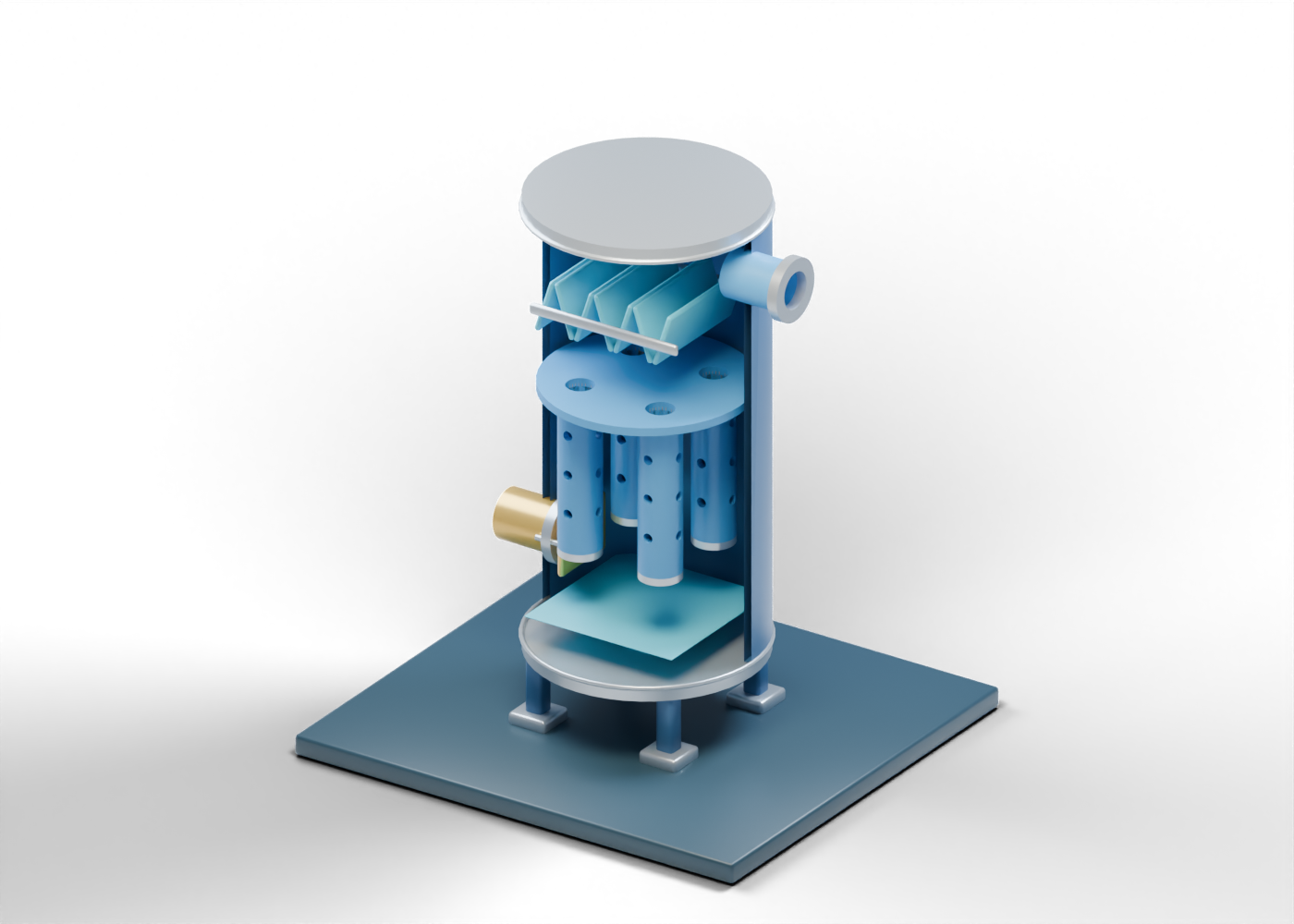
Filter-separator presentation plinth
Display base, not an installed foundation. Invented static teaching geometry; no selected cartridge media, flow distribution, removal efficiency, pressure drop, slug duty, rating, material, access, drain control or safe service is shown.
Complete hollow filter-separator wall
Complete double-surface enclosure with three real side bores; the lower drain passes through its separate cap. Invented static teaching geometry; no selected cartridge media, flow distribution, removal efficiency, pressure drop, slug duty, rating, material, access, drain control or safe service is shown.
Mixed gas inlet hollow neck
Open boundary at a real wall or lower-cap passage. Invented static teaching geometry; no selected cartridge media, flow distribution, removal efficiency, pressure drop, slug duty, rating, material, access, drain control or safe service is shown.
Mixed gas inlet open collar
Independent open connection marker; mating pipe omitted. Invented static teaching geometry; no selected cartridge media, flow distribution, removal efficiency, pressure drop, slug duty, rating, material, access, drain control or safe service is shown.
Gas outlet hollow neck
Open boundary at a real wall or lower-cap passage. Invented static teaching geometry; no selected cartridge media, flow distribution, removal efficiency, pressure drop, slug duty, rating, material, access, drain control or safe service is shown.
Gas outlet open collar
Independent open connection marker; mating pipe omitted. Invented static teaching geometry; no selected cartridge media, flow distribution, removal efficiency, pressure drop, slug duty, rating, material, access, drain control or safe service is shown.
Separate liquid drain hollow neck
Open boundary at a real wall or lower-cap passage. Invented static teaching geometry; no selected cartridge media, flow distribution, removal efficiency, pressure drop, slug duty, rating, material, access, drain control or safe service is shown.
Separate liquid drain open collar
Independent open connection marker; mating pipe omitted. Invented static teaching geometry; no selected cartridge media, flow distribution, removal efficiency, pressure drop, slug duty, rating, material, access, drain control or safe service is shown.
Lower closed vessel cap
Flat teaching closure, not a pressure-vessel head profile. Invented static teaching geometry; no selected cartridge media, flow distribution, removal efficiency, pressure drop, slug duty, rating, material, access, drain control or safe service is shown.
Upper closed vessel cap
Flat teaching closure, not a pressure-vessel head profile. Invented static teaching geometry; no selected cartridge media, flow distribution, removal efficiency, pressure drop, slug duty, rating, material, access, drain control or safe service is shown.
Lower enclosure seam marker
Visible boundary only; no weld, code or seal specification. Invented static teaching geometry; no selected cartridge media, flow distribution, removal efficiency, pressure drop, slug duty, rating, material, access, drain control or safe service is shown.
Upper enclosure seam marker
Visible boundary only; no weld, code or seal specification. Invented static teaching geometry; no selected cartridge media, flow distribution, removal efficiency, pressure drop, slug duty, rating, material, access, drain control or safe service is shown.
Separate inlet diversion marker
A possible bulk-liquid diversion location, not a tested device. Invented static teaching geometry; no selected cartridge media, flow distribution, removal efficiency, pressure drop, slug duty, rating, material, access, drain control or safe service is shown.
Inlet plate stand-off -0.28
Illustrative location tie without structural design. Invented static teaching geometry; no selected cartridge media, flow distribution, removal efficiency, pressure drop, slug duty, rating, material, access, drain control or safe service is shown.
Inlet plate stand-off 0.28
Illustrative location tie without structural design. Invented static teaching geometry; no selected cartridge media, flow distribution, removal efficiency, pressure drop, slug duty, rating, material, access, drain control or safe service is shown.
Perforated first-stage collector plate
Four real openings align with four generic cartridge bores; this is not a selected flow-distribution plate. Invented static teaching geometry; no selected cartridge media, flow distribution, removal efficiency, pressure drop, slug duty, rating, material, access, drain control or safe service is shown.
First-stage cartridge 1 open-bore envelope
Individually inspectable generic cartridge envelope; media, pore size and direction of flow are unspecified. Invented static teaching geometry; no selected cartridge media, flow distribution, removal efficiency, pressure drop, slug duty, rating, material, access, drain control or safe service is shown.
First-stage cartridge 1 separate lower end marker
Static lower end marker, not a specified seal or mounting. Invented static teaching geometry; no selected cartridge media, flow distribution, removal efficiency, pressure drop, slug duty, rating, material, access, drain control or safe service is shown.
First-stage cartridge 1 open upper rim
Open annular top, without cartridge retention detail. Invented static teaching geometry; no selected cartridge media, flow distribution, removal efficiency, pressure drop, slug duty, rating, material, access, drain control or safe service is shown.
First-stage cartridge 2 open-bore envelope
Individually inspectable generic cartridge envelope; media, pore size and direction of flow are unspecified. Invented static teaching geometry; no selected cartridge media, flow distribution, removal efficiency, pressure drop, slug duty, rating, material, access, drain control or safe service is shown.
First-stage cartridge 2 separate lower end marker
Static lower end marker, not a specified seal or mounting. Invented static teaching geometry; no selected cartridge media, flow distribution, removal efficiency, pressure drop, slug duty, rating, material, access, drain control or safe service is shown.
First-stage cartridge 2 open upper rim
Open annular top, without cartridge retention detail. Invented static teaching geometry; no selected cartridge media, flow distribution, removal efficiency, pressure drop, slug duty, rating, material, access, drain control or safe service is shown.
First-stage cartridge 3 open-bore envelope
Individually inspectable generic cartridge envelope; media, pore size and direction of flow are unspecified. Invented static teaching geometry; no selected cartridge media, flow distribution, removal efficiency, pressure drop, slug duty, rating, material, access, drain control or safe service is shown.
First-stage cartridge 3 separate lower end marker
Static lower end marker, not a specified seal or mounting. Invented static teaching geometry; no selected cartridge media, flow distribution, removal efficiency, pressure drop, slug duty, rating, material, access, drain control or safe service is shown.
First-stage cartridge 3 open upper rim
Open annular top, without cartridge retention detail. Invented static teaching geometry; no selected cartridge media, flow distribution, removal efficiency, pressure drop, slug duty, rating, material, access, drain control or safe service is shown.
First-stage cartridge 4 open-bore envelope
Individually inspectable generic cartridge envelope; media, pore size and direction of flow are unspecified. Invented static teaching geometry; no selected cartridge media, flow distribution, removal efficiency, pressure drop, slug duty, rating, material, access, drain control or safe service is shown.
First-stage cartridge 4 separate lower end marker
Static lower end marker, not a specified seal or mounting. Invented static teaching geometry; no selected cartridge media, flow distribution, removal efficiency, pressure drop, slug duty, rating, material, access, drain control or safe service is shown.
First-stage cartridge 4 open upper rim
Open annular top, without cartridge retention detail. Invented static teaching geometry; no selected cartridge media, flow distribution, removal efficiency, pressure drop, slug duty, rating, material, access, drain control or safe service is shown.
Second-stage mist vane 1
Distinct second-stage mist-removal marker; invented spacing and plate shape, with no capture claim. Invented static teaching geometry; no selected cartridge media, flow distribution, removal efficiency, pressure drop, slug duty, rating, material, access, drain control or safe service is shown.
Second-stage mist vane 2
Distinct second-stage mist-removal marker; invented spacing and plate shape, with no capture claim. Invented static teaching geometry; no selected cartridge media, flow distribution, removal efficiency, pressure drop, slug duty, rating, material, access, drain control or safe service is shown.
Second-stage mist vane 3
Distinct second-stage mist-removal marker; invented spacing and plate shape, with no capture claim. Invented static teaching geometry; no selected cartridge media, flow distribution, removal efficiency, pressure drop, slug duty, rating, material, access, drain control or safe service is shown.
Second-stage mist vane 4
Distinct second-stage mist-removal marker; invented spacing and plate shape, with no capture claim. Invented static teaching geometry; no selected cartridge media, flow distribution, removal efficiency, pressure drop, slug duty, rating, material, access, drain control or safe service is shown.
Second-stage mist vane 5
Distinct second-stage mist-removal marker; invented spacing and plate shape, with no capture claim. Invented static teaching geometry; no selected cartridge media, flow distribution, removal efficiency, pressure drop, slug duty, rating, material, access, drain control or safe service is shown.
Second-stage mist vane 6
Distinct second-stage mist-removal marker; invented spacing and plate shape, with no capture claim. Invented static teaching geometry; no selected cartridge media, flow distribution, removal efficiency, pressure drop, slug duty, rating, material, access, drain control or safe service is shown.
Second-stage mist vane 7
Distinct second-stage mist-removal marker; invented spacing and plate shape, with no capture claim. Invented static teaching geometry; no selected cartridge media, flow distribution, removal efficiency, pressure drop, slug duty, rating, material, access, drain control or safe service is shown.
Second-stage carrier rail -0.69
Static carrier location; no installed support design. Invented static teaching geometry; no selected cartridge media, flow distribution, removal efficiency, pressure drop, slug duty, rating, material, access, drain control or safe service is shown.
Second-stage carrier rail 0.69
Static carrier location; no installed support design. Invented static teaching geometry; no selected cartridge media, flow distribution, removal efficiency, pressure drop, slug duty, rating, material, access, drain control or safe service is shown.
Static sump liquid-region plane
Arbitrary blue location cue, not measured liquid level. Invented static teaching geometry; no selected cartridge media, flow distribution, removal efficiency, pressure drop, slug duty, rating, material, access, drain control or safe service is shown.
Inspection neck
Actual wall opening with separately closed cover; no entry procedure. Invented static teaching geometry; no selected cartridge media, flow distribution, removal efficiency, pressure drop, slug duty, rating, material, access, drain control or safe service is shown.
Inspection cover seat
Annular location marker, not a selected gasket or flange. Invented static teaching geometry; no selected cartridge media, flow distribution, removal efficiency, pressure drop, slug duty, rating, material, access, drain control or safe service is shown.
Closed inspection cover
Separate solid closure in a static pose; no vessel-access guidance. Invented static teaching geometry; no selected cartridge media, flow distribution, removal efficiency, pressure drop, slug duty, rating, material, access, drain control or safe service is shown.
Support leg 1
Illustrative support, without a load or foundation design. Invented static teaching geometry; no selected cartridge media, flow distribution, removal efficiency, pressure drop, slug duty, rating, material, access, drain control or safe service is shown.
Bored support foot 1
Separate foot with an actual anchor opening. Invented static teaching geometry; no selected cartridge media, flow distribution, removal efficiency, pressure drop, slug duty, rating, material, access, drain control or safe service is shown.
Support leg 2
Illustrative support, without a load or foundation design. Invented static teaching geometry; no selected cartridge media, flow distribution, removal efficiency, pressure drop, slug duty, rating, material, access, drain control or safe service is shown.
Bored support foot 2
Separate foot with an actual anchor opening. Invented static teaching geometry; no selected cartridge media, flow distribution, removal efficiency, pressure drop, slug duty, rating, material, access, drain control or safe service is shown.
Support leg 3
Illustrative support, without a load or foundation design. Invented static teaching geometry; no selected cartridge media, flow distribution, removal efficiency, pressure drop, slug duty, rating, material, access, drain control or safe service is shown.
Bored support foot 3
Separate foot with an actual anchor opening. Invented static teaching geometry; no selected cartridge media, flow distribution, removal efficiency, pressure drop, slug duty, rating, material, access, drain control or safe service is shown.
Support leg 4
Illustrative support, without a load or foundation design. Invented static teaching geometry; no selected cartridge media, flow distribution, removal efficiency, pressure drop, slug duty, rating, material, access, drain control or safe service is shown.
Bored support foot 4
Separate foot with an actual anchor opening. Invented static teaching geometry; no selected cartridge media, flow distribution, removal efficiency, pressure drop, slug duty, rating, material, access, drain control or safe service is shown.