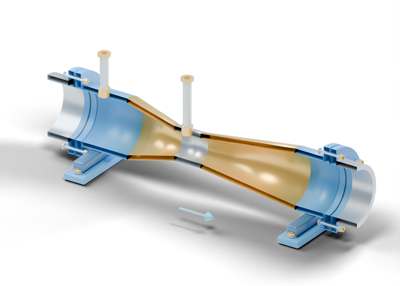
Upstream cylindrical passage
Separate hollow axial passage region with real nested surfaces and invented proportions. Original static teaching geometry; no measured flow/pressure, calibration, coefficient, leak, material, rating or service qualification.
Converging passage
Separate hollow axial passage region with real nested surfaces and invented proportions. Original static teaching geometry; no measured flow/pressure, calibration, coefficient, leak, material, rating or service qualification.
Throat passage
Separate hollow axial passage region with real nested surfaces and invented proportions. Original static teaching geometry; no measured flow/pressure, calibration, coefficient, leak, material, rating or service qualification.
Diverging passage
Separate hollow axial passage region with real nested surfaces and invented proportions. Original static teaching geometry; no measured flow/pressure, calibration, coefficient, leak, material, rating or service qualification.
Downstream cylindrical passage
Separate hollow axial passage region with real nested surfaces and invented proportions. Original static teaching geometry; no measured flow/pressure, calibration, coefficient, leak, material, rating or service qualification.
Upstream pressure-tap neck
Hollow pressure-tap location reaching the drilled passage wall; no selected tap diameter or connection. Original static teaching geometry; no measured flow/pressure, calibration, coefficient, leak, material, rating or service qualification.
Upstream pressure-line envelope
Open straight pressure-line envelope terminating independently; no connected transmitter, fluid fill or response. Original static teaching geometry; no measured flow/pressure, calibration, coefficient, leak, material, rating or service qualification.
Upstream line-end collar
Separate bored terminal collar without threads or selected fitting. Original static teaching geometry; no measured flow/pressure, calibration, coefficient, leak, material, rating or service qualification.
Throat pressure-tap neck
Hollow pressure-tap location reaching the drilled passage wall; no selected tap diameter or connection. Original static teaching geometry; no measured flow/pressure, calibration, coefficient, leak, material, rating or service qualification.
Throat pressure-line envelope
Open straight pressure-line envelope terminating independently; no connected transmitter, fluid fill or response. Original static teaching geometry; no measured flow/pressure, calibration, coefficient, leak, material, rating or service qualification.
Throat line-end collar
Separate bored terminal collar without threads or selected fitting. Original static teaching geometry; no measured flow/pressure, calibration, coefficient, leak, material, rating or service qualification.
Inlet element flange
Bored element flange with six invented true joint openings. Original static teaching geometry; no measured flow/pressure, calibration, coefficient, leak, material, rating or service qualification.
Inlet companion flange
Independent companion flange with six matching locations; no standard class or selected facing. Original static teaching geometry; no measured flow/pressure, calibration, coefficient, leak, material, rating or service qualification.
Inlet gasket location
Separate annular gasket location with a deliberate gap; no material, compression or leakage result. Original static teaching geometry; no measured flow/pressure, calibration, coefficient, leak, material, rating or service qualification.
Inlet boundary spool
Independent short open boundary pipe; adjacent installation and required straight lengths are unspecified. Original static teaching geometry; no measured flow/pressure, calibration, coefficient, leak, material, rating or service qualification.
Inlet joint 1 smooth stud
Separate smooth stud marker; no thread, preload or load path. Original static teaching geometry; no measured flow/pressure, calibration, coefficient, leak, material, rating or service qualification.
Inlet joint 1 left washer
Separate washer with a real central opening. Original static teaching geometry; no measured flow/pressure, calibration, coefficient, leak, material, rating or service qualification.
Inlet joint 1 right washer
Separate washer with a real central opening. Original static teaching geometry; no measured flow/pressure, calibration, coefficient, leak, material, rating or service qualification.
Inlet joint 1 nut
Hexagonal nut envelope with a true bore; no thread engagement. Original static teaching geometry; no measured flow/pressure, calibration, coefficient, leak, material, rating or service qualification.
Inlet joint 2 smooth stud
Separate smooth stud marker; no thread, preload or load path. Original static teaching geometry; no measured flow/pressure, calibration, coefficient, leak, material, rating or service qualification.
Inlet joint 2 left washer
Separate washer with a real central opening. Original static teaching geometry; no measured flow/pressure, calibration, coefficient, leak, material, rating or service qualification.
Inlet joint 2 right washer
Separate washer with a real central opening. Original static teaching geometry; no measured flow/pressure, calibration, coefficient, leak, material, rating or service qualification.
Inlet joint 2 nut
Hexagonal nut envelope with a true bore; no thread engagement. Original static teaching geometry; no measured flow/pressure, calibration, coefficient, leak, material, rating or service qualification.
Inlet joint 3 smooth stud
Separate smooth stud marker; no thread, preload or load path. Original static teaching geometry; no measured flow/pressure, calibration, coefficient, leak, material, rating or service qualification.
Inlet joint 3 left washer
Separate washer with a real central opening. Original static teaching geometry; no measured flow/pressure, calibration, coefficient, leak, material, rating or service qualification.
Inlet joint 3 right washer
Separate washer with a real central opening. Original static teaching geometry; no measured flow/pressure, calibration, coefficient, leak, material, rating or service qualification.
Inlet joint 3 nut
Hexagonal nut envelope with a true bore; no thread engagement. Original static teaching geometry; no measured flow/pressure, calibration, coefficient, leak, material, rating or service qualification.
Inlet joint 4 smooth stud
Separate smooth stud marker; no thread, preload or load path. Original static teaching geometry; no measured flow/pressure, calibration, coefficient, leak, material, rating or service qualification.
Inlet joint 4 left washer
Separate washer with a real central opening. Original static teaching geometry; no measured flow/pressure, calibration, coefficient, leak, material, rating or service qualification.
Inlet joint 4 right washer
Separate washer with a real central opening. Original static teaching geometry; no measured flow/pressure, calibration, coefficient, leak, material, rating or service qualification.
Inlet joint 4 nut
Hexagonal nut envelope with a true bore; no thread engagement. Original static teaching geometry; no measured flow/pressure, calibration, coefficient, leak, material, rating or service qualification.
Inlet joint 5 smooth stud
Separate smooth stud marker; no thread, preload or load path. Original static teaching geometry; no measured flow/pressure, calibration, coefficient, leak, material, rating or service qualification.
Inlet joint 5 left washer
Separate washer with a real central opening. Original static teaching geometry; no measured flow/pressure, calibration, coefficient, leak, material, rating or service qualification.
Inlet joint 5 right washer
Separate washer with a real central opening. Original static teaching geometry; no measured flow/pressure, calibration, coefficient, leak, material, rating or service qualification.
Inlet joint 5 nut
Hexagonal nut envelope with a true bore; no thread engagement. Original static teaching geometry; no measured flow/pressure, calibration, coefficient, leak, material, rating or service qualification.
Inlet joint 6 smooth stud
Separate smooth stud marker; no thread, preload or load path. Original static teaching geometry; no measured flow/pressure, calibration, coefficient, leak, material, rating or service qualification.
Inlet joint 6 left washer
Separate washer with a real central opening. Original static teaching geometry; no measured flow/pressure, calibration, coefficient, leak, material, rating or service qualification.
Inlet joint 6 right washer
Separate washer with a real central opening. Original static teaching geometry; no measured flow/pressure, calibration, coefficient, leak, material, rating or service qualification.
Inlet joint 6 nut
Hexagonal nut envelope with a true bore; no thread engagement. Original static teaching geometry; no measured flow/pressure, calibration, coefficient, leak, material, rating or service qualification.
Outlet element flange
Bored element flange with six invented true joint openings. Original static teaching geometry; no measured flow/pressure, calibration, coefficient, leak, material, rating or service qualification.
Outlet companion flange
Independent companion flange with six matching locations; no standard class or selected facing. Original static teaching geometry; no measured flow/pressure, calibration, coefficient, leak, material, rating or service qualification.
Outlet gasket location
Separate annular gasket location with a deliberate gap; no material, compression or leakage result. Original static teaching geometry; no measured flow/pressure, calibration, coefficient, leak, material, rating or service qualification.
Outlet boundary spool
Independent short open boundary pipe; adjacent installation and required straight lengths are unspecified. Original static teaching geometry; no measured flow/pressure, calibration, coefficient, leak, material, rating or service qualification.
Outlet joint 1 smooth stud
Separate smooth stud marker; no thread, preload or load path. Original static teaching geometry; no measured flow/pressure, calibration, coefficient, leak, material, rating or service qualification.
Outlet joint 1 left washer
Separate washer with a real central opening. Original static teaching geometry; no measured flow/pressure, calibration, coefficient, leak, material, rating or service qualification.
Outlet joint 1 right washer
Separate washer with a real central opening. Original static teaching geometry; no measured flow/pressure, calibration, coefficient, leak, material, rating or service qualification.
Outlet joint 1 nut
Hexagonal nut envelope with a true bore; no thread engagement. Original static teaching geometry; no measured flow/pressure, calibration, coefficient, leak, material, rating or service qualification.
Outlet joint 2 smooth stud
Separate smooth stud marker; no thread, preload or load path. Original static teaching geometry; no measured flow/pressure, calibration, coefficient, leak, material, rating or service qualification.
Outlet joint 2 left washer
Separate washer with a real central opening. Original static teaching geometry; no measured flow/pressure, calibration, coefficient, leak, material, rating or service qualification.
Outlet joint 2 right washer
Separate washer with a real central opening. Original static teaching geometry; no measured flow/pressure, calibration, coefficient, leak, material, rating or service qualification.
Outlet joint 2 nut
Hexagonal nut envelope with a true bore; no thread engagement. Original static teaching geometry; no measured flow/pressure, calibration, coefficient, leak, material, rating or service qualification.
Outlet joint 3 smooth stud
Separate smooth stud marker; no thread, preload or load path. Original static teaching geometry; no measured flow/pressure, calibration, coefficient, leak, material, rating or service qualification.
Outlet joint 3 left washer
Separate washer with a real central opening. Original static teaching geometry; no measured flow/pressure, calibration, coefficient, leak, material, rating or service qualification.
Outlet joint 3 right washer
Separate washer with a real central opening. Original static teaching geometry; no measured flow/pressure, calibration, coefficient, leak, material, rating or service qualification.
Outlet joint 3 nut
Hexagonal nut envelope with a true bore; no thread engagement. Original static teaching geometry; no measured flow/pressure, calibration, coefficient, leak, material, rating or service qualification.
Outlet joint 4 smooth stud
Separate smooth stud marker; no thread, preload or load path. Original static teaching geometry; no measured flow/pressure, calibration, coefficient, leak, material, rating or service qualification.
Outlet joint 4 left washer
Separate washer with a real central opening. Original static teaching geometry; no measured flow/pressure, calibration, coefficient, leak, material, rating or service qualification.
Outlet joint 4 right washer
Separate washer with a real central opening. Original static teaching geometry; no measured flow/pressure, calibration, coefficient, leak, material, rating or service qualification.
Outlet joint 4 nut
Hexagonal nut envelope with a true bore; no thread engagement. Original static teaching geometry; no measured flow/pressure, calibration, coefficient, leak, material, rating or service qualification.
Outlet joint 5 smooth stud
Separate smooth stud marker; no thread, preload or load path. Original static teaching geometry; no measured flow/pressure, calibration, coefficient, leak, material, rating or service qualification.
Outlet joint 5 left washer
Separate washer with a real central opening. Original static teaching geometry; no measured flow/pressure, calibration, coefficient, leak, material, rating or service qualification.
Outlet joint 5 right washer
Separate washer with a real central opening. Original static teaching geometry; no measured flow/pressure, calibration, coefficient, leak, material, rating or service qualification.
Outlet joint 5 nut
Hexagonal nut envelope with a true bore; no thread engagement. Original static teaching geometry; no measured flow/pressure, calibration, coefficient, leak, material, rating or service qualification.
Outlet joint 6 smooth stud
Separate smooth stud marker; no thread, preload or load path. Original static teaching geometry; no measured flow/pressure, calibration, coefficient, leak, material, rating or service qualification.
Outlet joint 6 left washer
Separate washer with a real central opening. Original static teaching geometry; no measured flow/pressure, calibration, coefficient, leak, material, rating or service qualification.
Outlet joint 6 right washer
Separate washer with a real central opening. Original static teaching geometry; no measured flow/pressure, calibration, coefficient, leak, material, rating or service qualification.
Outlet joint 6 nut
Hexagonal nut envelope with a true bore; no thread engagement. Original static teaching geometry; no measured flow/pressure, calibration, coefficient, leak, material, rating or service qualification.
Upstream support shoe
Independent support-location block with deliberate separation from the passage; no saddle fit or load calculation. Original static teaching geometry; no measured flow/pressure, calibration, coefficient, leak, material, rating or service qualification.
Upstream support foot
Separate foot envelope with two actual anchor-location bores. Original static teaching geometry; no measured flow/pressure, calibration, coefficient, leak, material, rating or service qualification.
Upstream foot joint 1 smooth anchor
Separate smooth anchor-location marker, with no embedment or foundation design. Original static teaching geometry; no measured flow/pressure, calibration, coefficient, leak, material, rating or service qualification.
Upstream foot joint 1 washer
Separate annular anchor washer. Original static teaching geometry; no measured flow/pressure, calibration, coefficient, leak, material, rating or service qualification.
Upstream foot joint 1 nut
Bored hexagonal anchor-nut envelope without thread engagement. Original static teaching geometry; no measured flow/pressure, calibration, coefficient, leak, material, rating or service qualification.
Upstream foot joint 2 smooth anchor
Separate smooth anchor-location marker, with no embedment or foundation design. Original static teaching geometry; no measured flow/pressure, calibration, coefficient, leak, material, rating or service qualification.
Upstream foot joint 2 washer
Separate annular anchor washer. Original static teaching geometry; no measured flow/pressure, calibration, coefficient, leak, material, rating or service qualification.
Upstream foot joint 2 nut
Bored hexagonal anchor-nut envelope without thread engagement. Original static teaching geometry; no measured flow/pressure, calibration, coefficient, leak, material, rating or service qualification.
Downstream support shoe
Independent support-location block with deliberate separation from the passage; no saddle fit or load calculation. Original static teaching geometry; no measured flow/pressure, calibration, coefficient, leak, material, rating or service qualification.
Downstream support foot
Separate foot envelope with two actual anchor-location bores. Original static teaching geometry; no measured flow/pressure, calibration, coefficient, leak, material, rating or service qualification.
Downstream foot joint 1 smooth anchor
Separate smooth anchor-location marker, with no embedment or foundation design. Original static teaching geometry; no measured flow/pressure, calibration, coefficient, leak, material, rating or service qualification.
Downstream foot joint 1 washer
Separate annular anchor washer. Original static teaching geometry; no measured flow/pressure, calibration, coefficient, leak, material, rating or service qualification.
Downstream foot joint 1 nut
Bored hexagonal anchor-nut envelope without thread engagement. Original static teaching geometry; no measured flow/pressure, calibration, coefficient, leak, material, rating or service qualification.
Downstream foot joint 2 smooth anchor
Separate smooth anchor-location marker, with no embedment or foundation design. Original static teaching geometry; no measured flow/pressure, calibration, coefficient, leak, material, rating or service qualification.
Downstream foot joint 2 washer
Separate annular anchor washer. Original static teaching geometry; no measured flow/pressure, calibration, coefficient, leak, material, rating or service qualification.
Downstream foot joint 2 nut
Bored hexagonal anchor-nut envelope without thread engagement. Original static teaching geometry; no measured flow/pressure, calibration, coefficient, leak, material, rating or service qualification.
Illustrative direction shaft
Static arrow shaft for the invented upstream-to-throat-to-outlet reading direction. No fluid velocity or flow rate. Original static teaching geometry; no measured flow/pressure, calibration, coefficient, leak, material, rating or service qualification.
Illustrative direction head
Static annotation outside the passage; no live or simulated flow. Original static teaching geometry; no measured flow/pressure, calibration, coefficient, leak, material, rating or service qualification.