Reservoir-section base
Open-front section support; no formation or foundation dimensions. Invented geometric teaching marker only; no well design, reservoir forecast, completion specification, pressure, temperature or recovery result.
Illustrative reservoir backplane
Brown backdrop locates the two horizontal well paths in an invented reservoir section. Invented geometric teaching marker only; no well design, reservoir forecast, completion specification, pressure, temperature or recovery result.
Illustrative upper boundary
Simple upper marker for reading the scene; not a mapped caprock or containment claim. Invented geometric teaching marker only; no well design, reservoir forecast, completion specification, pressure, temperature or recovery result.
Overburden backplane
Separate overburden colour block; no stratigraphy, depth or rock properties are represented. Invented geometric teaching marker only; no well design, reservoir forecast, completion specification, pressure, temperature or recovery result.
Reservoir-section floor
Lower visual boundary of this open-front teaching section. Invented geometric teaching marker only; no well design, reservoir forecast, completion specification, pressure, temperature or recovery result.
Ground-surface slab
Two actual openings receive the independently drawn injector and producer paths. Invented geometric teaching marker only; no well design, reservoir forecast, completion specification, pressure, temperature or recovery result.
Injector surface opening ring
Open visual boundary at the ground plane, without casing program or surface seal design. Invented geometric teaching marker only; no well design, reservoir forecast, completion specification, pressure, temperature or recovery result.
Producer surface opening ring
Open visual boundary at the ground plane, without casing program or surface seal design. Invented geometric teaching marker only; no well design, reservoir forecast, completion specification, pressure, temperature or recovery result.
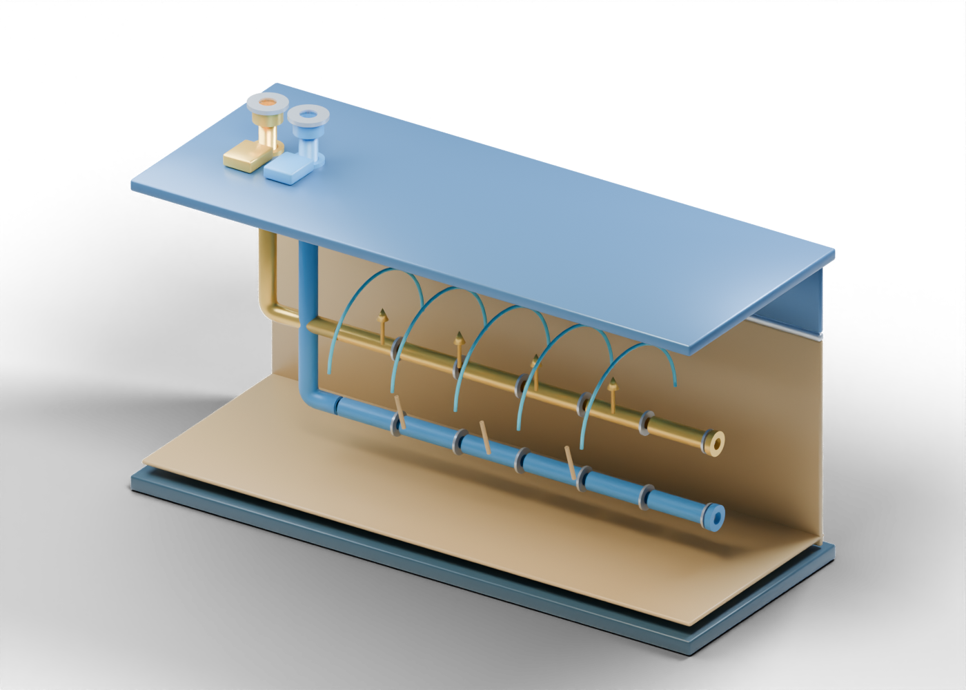
Injector curved well path
Upper path turns from the surface into the horizontal injector role. It is open at both ends. Invented geometric teaching marker only; no well design, reservoir forecast, completion specification, pressure, temperature or recovery result.
Producer curved well path
Lower path turns toward the produced-fluid surface boundary. It is open at both ends. Invented geometric teaching marker only; no well design, reservoir forecast, completion specification, pressure, temperature or recovery result.
Injector surface spool
Unrated surface connection marker; steam supply or produced-fluid handling remains outside this scene. Invented geometric teaching marker only; no well design, reservoir forecast, completion specification, pressure, temperature or recovery result.
Injector open boundary collar
Open endpoint, without wellhead pressure control, valves or external facilities. Invented geometric teaching marker only; no well design, reservoir forecast, completion specification, pressure, temperature or recovery result.
Injector surface identification plinth
A colour-coded label location, not a pad survey, construction plan or safe-access platform. Invented geometric teaching marker only; no well design, reservoir forecast, completion specification, pressure, temperature or recovery result.
Producer surface spool
Unrated surface connection marker; steam supply or produced-fluid handling remains outside this scene. Invented geometric teaching marker only; no well design, reservoir forecast, completion specification, pressure, temperature or recovery result.
Producer open boundary collar
Open endpoint, without wellhead pressure control, valves or external facilities. Invented geometric teaching marker only; no well design, reservoir forecast, completion specification, pressure, temperature or recovery result.
Producer surface identification plinth
A colour-coded label location, not a pad survey, construction plan or safe-access platform. Invented geometric teaching marker only; no well design, reservoir forecast, completion specification, pressure, temperature or recovery result.
Injector open liner section 1
One separate hollow, open-ended teaching section. Small gaps expose the path; they are not a perforation, slot size or completion design. Invented geometric teaching marker only; no well design, reservoir forecast, completion specification, pressure, temperature or recovery result.
Injector liner end marker 1
Separate annular section-end marker; it does not establish a joint, screen or liner specification. Invented geometric teaching marker only; no well design, reservoir forecast, completion specification, pressure, temperature or recovery result.
Injector open liner section 2
One separate hollow, open-ended teaching section. Small gaps expose the path; they are not a perforation, slot size or completion design. Invented geometric teaching marker only; no well design, reservoir forecast, completion specification, pressure, temperature or recovery result.
Injector liner end marker 2
Separate annular section-end marker; it does not establish a joint, screen or liner specification. Invented geometric teaching marker only; no well design, reservoir forecast, completion specification, pressure, temperature or recovery result.
Injector open liner section 3
One separate hollow, open-ended teaching section. Small gaps expose the path; they are not a perforation, slot size or completion design. Invented geometric teaching marker only; no well design, reservoir forecast, completion specification, pressure, temperature or recovery result.
Injector liner end marker 3
Separate annular section-end marker; it does not establish a joint, screen or liner specification. Invented geometric teaching marker only; no well design, reservoir forecast, completion specification, pressure, temperature or recovery result.
Injector open liner section 4
One separate hollow, open-ended teaching section. Small gaps expose the path; they are not a perforation, slot size or completion design. Invented geometric teaching marker only; no well design, reservoir forecast, completion specification, pressure, temperature or recovery result.
Injector liner end marker 4
Separate annular section-end marker; it does not establish a joint, screen or liner specification. Invented geometric teaching marker only; no well design, reservoir forecast, completion specification, pressure, temperature or recovery result.
Injector open liner section 5
One separate hollow, open-ended teaching section. Small gaps expose the path; they are not a perforation, slot size or completion design. Invented geometric teaching marker only; no well design, reservoir forecast, completion specification, pressure, temperature or recovery result.
Injector liner end marker 5
Separate annular section-end marker; it does not establish a joint, screen or liner specification. Invented geometric teaching marker only; no well design, reservoir forecast, completion specification, pressure, temperature or recovery result.
Injector open liner section 6
One separate hollow, open-ended teaching section. Small gaps expose the path; they are not a perforation, slot size or completion design. Invented geometric teaching marker only; no well design, reservoir forecast, completion specification, pressure, temperature or recovery result.
Injector liner end marker 6
Separate annular section-end marker; it does not establish a joint, screen or liner specification. Invented geometric teaching marker only; no well design, reservoir forecast, completion specification, pressure, temperature or recovery result.
Injector distal open end
Open far-end marker. No length, toe isolation, steam distribution or inflow profile is inferred. Invented geometric teaching marker only; no well design, reservoir forecast, completion specification, pressure, temperature or recovery result.
Producer open liner section 1
One separate hollow, open-ended teaching section. Small gaps expose the path; they are not a perforation, slot size or completion design. Invented geometric teaching marker only; no well design, reservoir forecast, completion specification, pressure, temperature or recovery result.
Producer liner end marker 1
Separate annular section-end marker; it does not establish a joint, screen or liner specification. Invented geometric teaching marker only; no well design, reservoir forecast, completion specification, pressure, temperature or recovery result.
Producer open liner section 2
One separate hollow, open-ended teaching section. Small gaps expose the path; they are not a perforation, slot size or completion design. Invented geometric teaching marker only; no well design, reservoir forecast, completion specification, pressure, temperature or recovery result.
Producer liner end marker 2
Separate annular section-end marker; it does not establish a joint, screen or liner specification. Invented geometric teaching marker only; no well design, reservoir forecast, completion specification, pressure, temperature or recovery result.
Producer open liner section 3
One separate hollow, open-ended teaching section. Small gaps expose the path; they are not a perforation, slot size or completion design. Invented geometric teaching marker only; no well design, reservoir forecast, completion specification, pressure, temperature or recovery result.
Producer liner end marker 3
Separate annular section-end marker; it does not establish a joint, screen or liner specification. Invented geometric teaching marker only; no well design, reservoir forecast, completion specification, pressure, temperature or recovery result.
Producer open liner section 4
One separate hollow, open-ended teaching section. Small gaps expose the path; they are not a perforation, slot size or completion design. Invented geometric teaching marker only; no well design, reservoir forecast, completion specification, pressure, temperature or recovery result.
Producer liner end marker 4
Separate annular section-end marker; it does not establish a joint, screen or liner specification. Invented geometric teaching marker only; no well design, reservoir forecast, completion specification, pressure, temperature or recovery result.
Producer open liner section 5
One separate hollow, open-ended teaching section. Small gaps expose the path; they are not a perforation, slot size or completion design. Invented geometric teaching marker only; no well design, reservoir forecast, completion specification, pressure, temperature or recovery result.
Producer liner end marker 5
Separate annular section-end marker; it does not establish a joint, screen or liner specification. Invented geometric teaching marker only; no well design, reservoir forecast, completion specification, pressure, temperature or recovery result.
Producer open liner section 6
One separate hollow, open-ended teaching section. Small gaps expose the path; they are not a perforation, slot size or completion design. Invented geometric teaching marker only; no well design, reservoir forecast, completion specification, pressure, temperature or recovery result.
Producer liner end marker 6
Separate annular section-end marker; it does not establish a joint, screen or liner specification. Invented geometric teaching marker only; no well design, reservoir forecast, completion specification, pressure, temperature or recovery result.
Producer distal open end
Open far-end marker. No length, toe isolation, steam distribution or inflow profile is inferred. Invented geometric teaching marker only; no well design, reservoir forecast, completion specification, pressure, temperature or recovery result.
Steam-chamber outline 1
Open arch marks a possible conceptual heated region above the injector. It is not a simulated chamber surface, observed extent or thermal front. Invented geometric teaching marker only; no well design, reservoir forecast, completion specification, pressure, temperature or recovery result.
Steam-chamber outline 2
Open arch marks a possible conceptual heated region above the injector. It is not a simulated chamber surface, observed extent or thermal front. Invented geometric teaching marker only; no well design, reservoir forecast, completion specification, pressure, temperature or recovery result.
Steam-chamber outline 3
Open arch marks a possible conceptual heated region above the injector. It is not a simulated chamber surface, observed extent or thermal front. Invented geometric teaching marker only; no well design, reservoir forecast, completion specification, pressure, temperature or recovery result.
Steam-chamber outline 4
Open arch marks a possible conceptual heated region above the injector. It is not a simulated chamber surface, observed extent or thermal front. Invented geometric teaching marker only; no well design, reservoir forecast, completion specification, pressure, temperature or recovery result.
Steam-chamber outline 5
Open arch marks a possible conceptual heated region above the injector. It is not a simulated chamber surface, observed extent or thermal front. Invented geometric teaching marker only; no well design, reservoir forecast, completion specification, pressure, temperature or recovery result.
Illustrative upward steam marker 1
Static upward reading direction only; no pressure, phase transport or steam rate is modeled. Invented geometric teaching marker only; no well design, reservoir forecast, completion specification, pressure, temperature or recovery result.
Illustrative upward arrow head 1
Static directional marker, not calculated steam movement. Invented geometric teaching marker only; no well design, reservoir forecast, completion specification, pressure, temperature or recovery result.
Illustrative upward steam marker 2
Static upward reading direction only; no pressure, phase transport or steam rate is modeled. Invented geometric teaching marker only; no well design, reservoir forecast, completion specification, pressure, temperature or recovery result.
Illustrative upward arrow head 2
Static directional marker, not calculated steam movement. Invented geometric teaching marker only; no well design, reservoir forecast, completion specification, pressure, temperature or recovery result.
Illustrative upward steam marker 3
Static upward reading direction only; no pressure, phase transport or steam rate is modeled. Invented geometric teaching marker only; no well design, reservoir forecast, completion specification, pressure, temperature or recovery result.
Illustrative upward arrow head 3
Static directional marker, not calculated steam movement. Invented geometric teaching marker only; no well design, reservoir forecast, completion specification, pressure, temperature or recovery result.
Illustrative upward steam marker 4
Static upward reading direction only; no pressure, phase transport or steam rate is modeled. Invented geometric teaching marker only; no well design, reservoir forecast, completion specification, pressure, temperature or recovery result.
Illustrative upward arrow head 4
Static directional marker, not calculated steam movement. Invented geometric teaching marker only; no well design, reservoir forecast, completion specification, pressure, temperature or recovery result.
Illustrative gravity-drainage marker 1
Static downward reading path from the heated-region concept toward the lower producer. No actual drainage or recovery is simulated. Invented geometric teaching marker only; no well design, reservoir forecast, completion specification, pressure, temperature or recovery result.
Illustrative gravity-drainage marker 2
Static downward reading path from the heated-region concept toward the lower producer. No actual drainage or recovery is simulated. Invented geometric teaching marker only; no well design, reservoir forecast, completion specification, pressure, temperature or recovery result.
Illustrative gravity-drainage marker 3
Static downward reading path from the heated-region concept toward the lower producer. No actual drainage or recovery is simulated. Invented geometric teaching marker only; no well design, reservoir forecast, completion specification, pressure, temperature or recovery result.