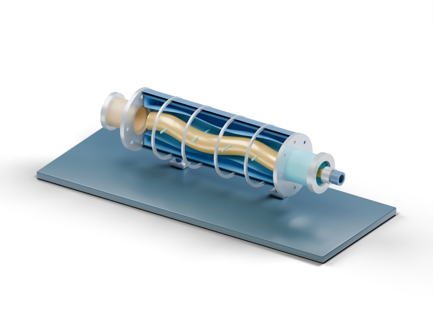
PCP presentation plinth
Display base, not a foundation. Invented static teaching geometry. No selected fluid, elastomer, fit, contact seal, displacement, rotation, torque, pressure, temperature, wear, production rate or safe service.
Complete steel stator housing wall
Complete double-surface housing, open at both ends. The poster alone exposes the facing half. Invented static teaching geometry. No selected fluid, elastomer, fit, contact seal, displacement, rotation, torque, pressure, temperature, wear, production rate or safe service.
Double-lobe stator liner teaching surface
Original helically contoured inner surface and independent outer wall. This is not a manufactured stator or selected elastomer. Invented static teaching geometry. No selected fluid, elastomer, fit, contact seal, displacement, rotation, torque, pressure, temperature, wear, production rate or safe service.
Eccentric single-helix rotor teaching surface
Original eccentric helical centreline and closed solid end faces. Static pose only; no meshing, cavity sealing or rotation simulated. Invented static teaching geometry. No selected fluid, elastomer, fit, contact seal, displacement, rotation, torque, pressure, temperature, wear, production rate or safe service.
Intake rotor end marker
Static rotor-end cue, without a selected connection. Invented static teaching geometry. No selected fluid, elastomer, fit, contact seal, displacement, rotation, torque, pressure, temperature, wear, production rate or safe service.
Drive rotor end marker
Static rotor-end cue, without a selected connection. Invented static teaching geometry. No selected fluid, elastomer, fit, contact seal, displacement, rotation, torque, pressure, temperature, wear, production rate or safe service.
Intake bored end plate
Separate end-location plate with central opening and eight real perimeter holes; not a rated joint. Invented static teaching geometry. No selected fluid, elastomer, fit, contact seal, displacement, rotation, torque, pressure, temperature, wear, production rate or safe service.
Discharge and drive bored end plate
Separate end-location plate with central opening and eight real perimeter holes; not a rated joint. Invented static teaching geometry. No selected fluid, elastomer, fit, contact seal, displacement, rotation, torque, pressure, temperature, wear, production rate or safe service.
Open produced-fluid intake sleeve
Open axial arrival boundary, without a well completion or selected intake screen. Invented static teaching geometry. No selected fluid, elastomer, fit, contact seal, displacement, rotation, torque, pressure, temperature, wear, production rate or safe service.
Intake open end collar
Unrated open intake marker. Invented static teaching geometry. No selected fluid, elastomer, fit, contact seal, displacement, rotation, torque, pressure, temperature, wear, production rate or safe service.
Open annular discharge sleeve
Open annular destination around the drive-rod cue; not a fabricated flow passage. Invented static teaching geometry. No selected fluid, elastomer, fit, contact seal, displacement, rotation, torque, pressure, temperature, wear, production rate or safe service.
Discharge open end collar
Unrated open discharge marker. Invented static teaching geometry. No selected fluid, elastomer, fit, contact seal, displacement, rotation, torque, pressure, temperature, wear, production rate or safe service.
Static drive-rod extension
Shaft/rod location beyond the stator. It does not rotate or specify a rod string. Invented static teaching geometry. No selected fluid, elastomer, fit, contact seal, displacement, rotation, torque, pressure, temperature, wear, production rate or safe service.
Drive coupling envelope
Unrated coupling-location envelope, not a connection drawing. Invented static teaching geometry. No selected fluid, elastomer, fit, contact seal, displacement, rotation, torque, pressure, temperature, wear, production rate or safe service.
Open rod continuation marker
Boundary for a possible drive train outside this component scene. Invented static teaching geometry. No selected fluid, elastomer, fit, contact seal, displacement, rotation, torque, pressure, temperature, wear, production rate or safe service.
Housing section-reference ring 1
Visual section marker; not a joint or fastening feature. Invented static teaching geometry. No selected fluid, elastomer, fit, contact seal, displacement, rotation, torque, pressure, temperature, wear, production rate or safe service.
Housing section-reference ring 2
Visual section marker; not a joint or fastening feature. Invented static teaching geometry. No selected fluid, elastomer, fit, contact seal, displacement, rotation, torque, pressure, temperature, wear, production rate or safe service.
Housing section-reference ring 3
Visual section marker; not a joint or fastening feature. Invented static teaching geometry. No selected fluid, elastomer, fit, contact seal, displacement, rotation, torque, pressure, temperature, wear, production rate or safe service.
Housing section-reference ring 4
Visual section marker; not a joint or fastening feature. Invented static teaching geometry. No selected fluid, elastomer, fit, contact seal, displacement, rotation, torque, pressure, temperature, wear, production rate or safe service.
Static cavity-reading marker 1
Open visual reading marker. It is not a sealed cavity, fluid particle path or volume measurement. Invented static teaching geometry. No selected fluid, elastomer, fit, contact seal, displacement, rotation, torque, pressure, temperature, wear, production rate or safe service.
Static cavity-reading marker 2
Open visual reading marker. It is not a sealed cavity, fluid particle path or volume measurement. Invented static teaching geometry. No selected fluid, elastomer, fit, contact seal, displacement, rotation, torque, pressure, temperature, wear, production rate or safe service.
Static cavity-reading marker 3
Open visual reading marker. It is not a sealed cavity, fluid particle path or volume measurement. Invented static teaching geometry. No selected fluid, elastomer, fit, contact seal, displacement, rotation, torque, pressure, temperature, wear, production rate or safe service.
Static cavity-reading marker 4
Open visual reading marker. It is not a sealed cavity, fluid particle path or volume measurement. Invented static teaching geometry. No selected fluid, elastomer, fit, contact seal, displacement, rotation, torque, pressure, temperature, wear, production rate or safe service.
PCP support stand 1
Display support, not a structural or downhole support design. Invented static teaching geometry. No selected fluid, elastomer, fit, contact seal, displacement, rotation, torque, pressure, temperature, wear, production rate or safe service.
PCP bored presentation foot 1
Independent visual foot with an actual opening. Invented static teaching geometry. No selected fluid, elastomer, fit, contact seal, displacement, rotation, torque, pressure, temperature, wear, production rate or safe service.
PCP support stand 2
Display support, not a structural or downhole support design. Invented static teaching geometry. No selected fluid, elastomer, fit, contact seal, displacement, rotation, torque, pressure, temperature, wear, production rate or safe service.
PCP bored presentation foot 2
Independent visual foot with an actual opening. Invented static teaching geometry. No selected fluid, elastomer, fit, contact seal, displacement, rotation, torque, pressure, temperature, wear, production rate or safe service.
PCP support stand 3
Display support, not a structural or downhole support design. Invented static teaching geometry. No selected fluid, elastomer, fit, contact seal, displacement, rotation, torque, pressure, temperature, wear, production rate or safe service.
PCP bored presentation foot 3
Independent visual foot with an actual opening. Invented static teaching geometry. No selected fluid, elastomer, fit, contact seal, displacement, rotation, torque, pressure, temperature, wear, production rate or safe service.
PCP support stand 4
Display support, not a structural or downhole support design. Invented static teaching geometry. No selected fluid, elastomer, fit, contact seal, displacement, rotation, torque, pressure, temperature, wear, production rate or safe service.
PCP bored presentation foot 4
Independent visual foot with an actual opening. Invented static teaching geometry. No selected fluid, elastomer, fit, contact seal, displacement, rotation, torque, pressure, temperature, wear, production rate or safe service.