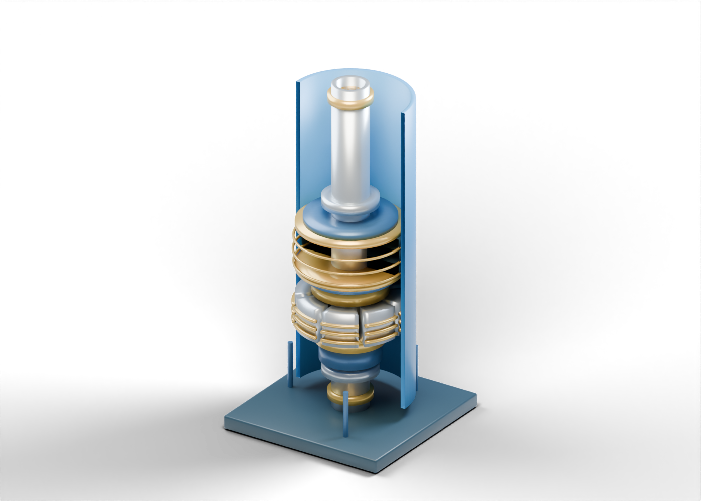
Complete open production casing
Outer wellbore conduit. The casing is a context boundary, not a selected string. Invented static teaching geometry; no selected size, load, pressure, seal performance, material or field setting procedure.
Open production tubing mandrel
Continuous hollow production path passing through the packer. Invented static teaching geometry; no selected size, load, pressure, seal performance, material or field setting procedure.
Upper tubing connection marker
Visual tubing joint location without threads, sealing or strength rating. Invented static teaching geometry; no selected size, load, pressure, seal performance, material or field setting procedure.
Lower tubing connection marker
Visual tubing joint location without threads, sealing or strength rating. Invented static teaching geometry; no selected size, load, pressure, seal performance, material or field setting procedure.
Upper element retainer
Conceptual upper compression boundary, not a set-force calculation. Invented static teaching geometry; no selected size, load, pressure, seal performance, material or field setting procedure.
Upper anti-extrusion marker
Generic backup location; no extrusion resistance is demonstrated. Invented static teaching geometry; no selected size, load, pressure, seal performance, material or field setting procedure.
Expandable elastomer element 1
One of three separate illustrative elastomer bands near the casing wall. No verified seal or compound. Invented static teaching geometry; no selected size, load, pressure, seal performance, material or field setting procedure.
Element contrast band 1
Narrow visual band that makes the element stack readable, not a measured interface. Invented static teaching geometry; no selected size, load, pressure, seal performance, material or field setting procedure.
Expandable elastomer element 2
One of three separate illustrative elastomer bands near the casing wall. No verified seal or compound. Invented static teaching geometry; no selected size, load, pressure, seal performance, material or field setting procedure.
Element contrast band 2
Narrow visual band that makes the element stack readable, not a measured interface. Invented static teaching geometry; no selected size, load, pressure, seal performance, material or field setting procedure.
Expandable elastomer element 3
One of three separate illustrative elastomer bands near the casing wall. No verified seal or compound. Invented static teaching geometry; no selected size, load, pressure, seal performance, material or field setting procedure.
Element contrast band 3
Narrow visual band that makes the element stack readable, not a measured interface. Invented static teaching geometry; no selected size, load, pressure, seal performance, material or field setting procedure.
Lower anti-extrusion marker
Generic lower backup location; no differential-pressure rating. Invented static teaching geometry; no selected size, load, pressure, seal performance, material or field setting procedure.
Lower element retainer
Conceptual lower compression boundary, not an actual setting mechanism. Invented static teaching geometry; no selected size, load, pressure, seal performance, material or field setting procedure.
Upper slip cone marker
Invented taper-role marker next to the grips; no wedge action is simulated. Invented static teaching geometry; no selected size, load, pressure, seal performance, material or field setting procedure.
Grip slip segment 1
Individual segmented anchoring role; no setting or release sequence. Invented static teaching geometry; no selected size, load, pressure, seal performance, material or field setting procedure.
Slip 1 tooth 1
Individual static casing-grip role; no teeth engagement, holding force or movement. Invented static teaching geometry; no selected size, load, pressure, seal performance, material or field setting procedure.
Slip 1 tooth 2
Individual static casing-grip role; no teeth engagement, holding force or movement. Invented static teaching geometry; no selected size, load, pressure, seal performance, material or field setting procedure.
Slip 1 tooth 3
Individual static casing-grip role; no teeth engagement, holding force or movement. Invented static teaching geometry; no selected size, load, pressure, seal performance, material or field setting procedure.
Grip slip segment 2
Individual segmented anchoring role; no setting or release sequence. Invented static teaching geometry; no selected size, load, pressure, seal performance, material or field setting procedure.
Slip 2 tooth 1
Individual static casing-grip role; no teeth engagement, holding force or movement. Invented static teaching geometry; no selected size, load, pressure, seal performance, material or field setting procedure.
Slip 2 tooth 2
Individual static casing-grip role; no teeth engagement, holding force or movement. Invented static teaching geometry; no selected size, load, pressure, seal performance, material or field setting procedure.
Slip 2 tooth 3
Individual static casing-grip role; no teeth engagement, holding force or movement. Invented static teaching geometry; no selected size, load, pressure, seal performance, material or field setting procedure.
Grip slip segment 3
Individual segmented anchoring role; no setting or release sequence. Invented static teaching geometry; no selected size, load, pressure, seal performance, material or field setting procedure.
Slip 3 tooth 1
Individual static casing-grip role; no teeth engagement, holding force or movement. Invented static teaching geometry; no selected size, load, pressure, seal performance, material or field setting procedure.
Slip 3 tooth 2
Individual static casing-grip role; no teeth engagement, holding force or movement. Invented static teaching geometry; no selected size, load, pressure, seal performance, material or field setting procedure.
Slip 3 tooth 3
Individual static casing-grip role; no teeth engagement, holding force or movement. Invented static teaching geometry; no selected size, load, pressure, seal performance, material or field setting procedure.
Grip slip segment 4
Individual segmented anchoring role; no setting or release sequence. Invented static teaching geometry; no selected size, load, pressure, seal performance, material or field setting procedure.
Slip 4 tooth 1
Individual static casing-grip role; no teeth engagement, holding force or movement. Invented static teaching geometry; no selected size, load, pressure, seal performance, material or field setting procedure.
Slip 4 tooth 2
Individual static casing-grip role; no teeth engagement, holding force or movement. Invented static teaching geometry; no selected size, load, pressure, seal performance, material or field setting procedure.
Slip 4 tooth 3
Individual static casing-grip role; no teeth engagement, holding force or movement. Invented static teaching geometry; no selected size, load, pressure, seal performance, material or field setting procedure.
Grip slip segment 5
Individual segmented anchoring role; no setting or release sequence. Invented static teaching geometry; no selected size, load, pressure, seal performance, material or field setting procedure.
Slip 5 tooth 1
Individual static casing-grip role; no teeth engagement, holding force or movement. Invented static teaching geometry; no selected size, load, pressure, seal performance, material or field setting procedure.
Slip 5 tooth 2
Individual static casing-grip role; no teeth engagement, holding force or movement. Invented static teaching geometry; no selected size, load, pressure, seal performance, material or field setting procedure.
Slip 5 tooth 3
Individual static casing-grip role; no teeth engagement, holding force or movement. Invented static teaching geometry; no selected size, load, pressure, seal performance, material or field setting procedure.
Grip slip segment 6
Individual segmented anchoring role; no setting or release sequence. Invented static teaching geometry; no selected size, load, pressure, seal performance, material or field setting procedure.
Slip 6 tooth 1
Individual static casing-grip role; no teeth engagement, holding force or movement. Invented static teaching geometry; no selected size, load, pressure, seal performance, material or field setting procedure.
Slip 6 tooth 2
Individual static casing-grip role; no teeth engagement, holding force or movement. Invented static teaching geometry; no selected size, load, pressure, seal performance, material or field setting procedure.
Slip 6 tooth 3
Individual static casing-grip role; no teeth engagement, holding force or movement. Invented static teaching geometry; no selected size, load, pressure, seal performance, material or field setting procedure.
Grip slip segment 7
Individual segmented anchoring role; no setting or release sequence. Invented static teaching geometry; no selected size, load, pressure, seal performance, material or field setting procedure.
Slip 7 tooth 1
Individual static casing-grip role; no teeth engagement, holding force or movement. Invented static teaching geometry; no selected size, load, pressure, seal performance, material or field setting procedure.
Slip 7 tooth 2
Individual static casing-grip role; no teeth engagement, holding force or movement. Invented static teaching geometry; no selected size, load, pressure, seal performance, material or field setting procedure.
Slip 7 tooth 3
Individual static casing-grip role; no teeth engagement, holding force or movement. Invented static teaching geometry; no selected size, load, pressure, seal performance, material or field setting procedure.
Grip slip segment 8
Individual segmented anchoring role; no setting or release sequence. Invented static teaching geometry; no selected size, load, pressure, seal performance, material or field setting procedure.
Slip 8 tooth 1
Individual static casing-grip role; no teeth engagement, holding force or movement. Invented static teaching geometry; no selected size, load, pressure, seal performance, material or field setting procedure.
Slip 8 tooth 2
Individual static casing-grip role; no teeth engagement, holding force or movement. Invented static teaching geometry; no selected size, load, pressure, seal performance, material or field setting procedure.
Slip 8 tooth 3
Individual static casing-grip role; no teeth engagement, holding force or movement. Invented static teaching geometry; no selected size, load, pressure, seal performance, material or field setting procedure.
Lower slip cone marker
Generic taper-role marker beneath slips; not a selected cone or release mechanism. Invented static teaching geometry; no selected size, load, pressure, seal performance, material or field setting procedure.
Lower setting sleeve envelope
Location cue for a setting sleeve; no hydraulic chamber or mechanical stroke is modeled. Invented static teaching geometry; no selected size, load, pressure, seal performance, material or field setting procedure.
Lower guide collar
Visual guide location, not a threaded or rated tubing connection. Invented static teaching geometry; no selected size, load, pressure, seal performance, material or field setting procedure.
Upper guide collar
Visual upper guide location, not an installed completion feature. Invented static teaching geometry; no selected size, load, pressure, seal performance, material or field setting procedure.
Presentation rail 1
External display-only rail, not part of a completion. Invented static teaching geometry; no selected size, load, pressure, seal performance, material or field setting procedure.
Presentation rail 2
External display-only rail, not part of a completion. Invented static teaching geometry; no selected size, load, pressure, seal performance, material or field setting procedure.
Presentation rail 3
External display-only rail, not part of a completion. Invented static teaching geometry; no selected size, load, pressure, seal performance, material or field setting procedure.
Base frame
Illustrative support frame; foundations and structural design vary.