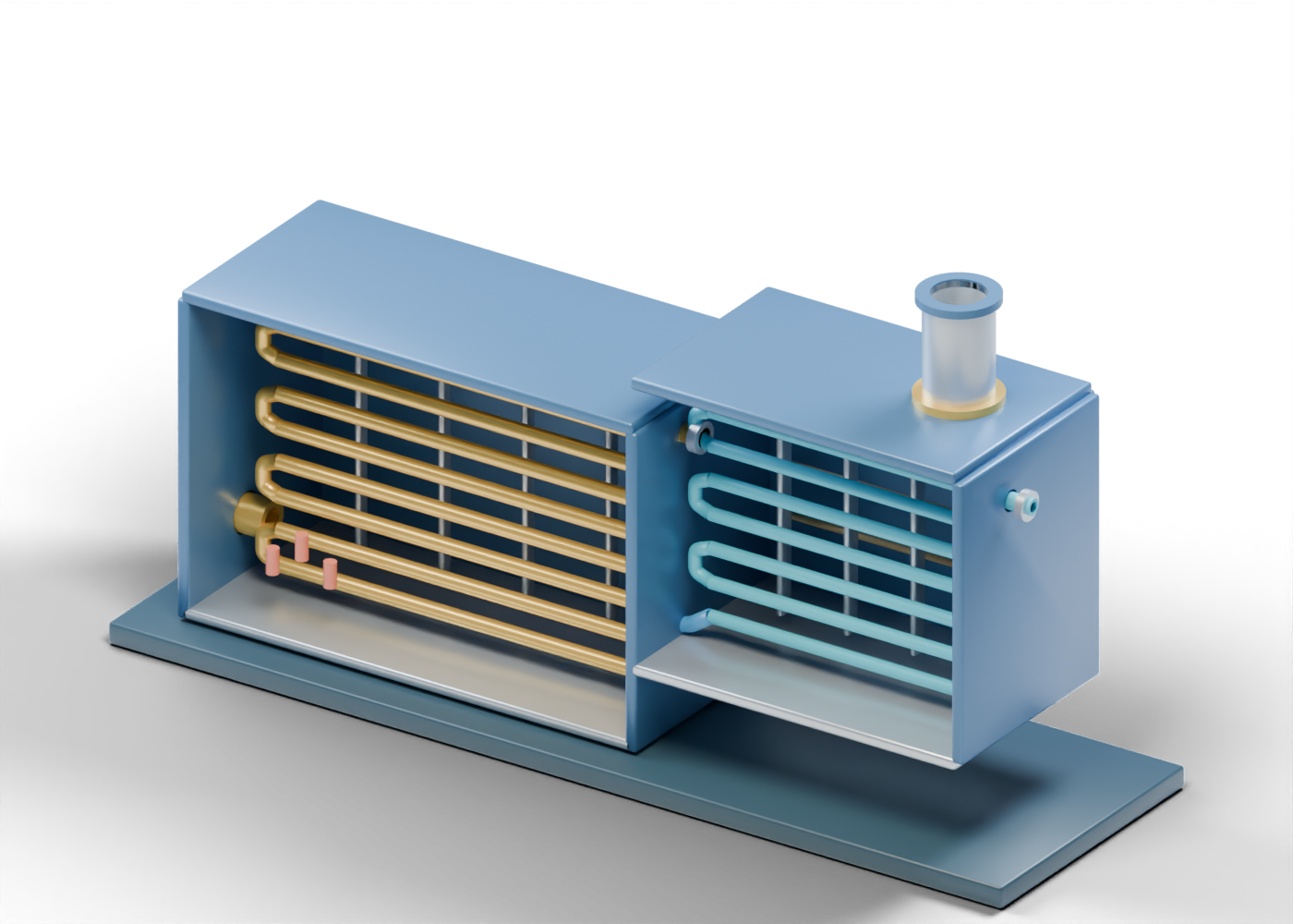
Generator skid base
Visual support footprint, not a foundation or transportable skid design. Invented schematic geometry only. No tube schedule, fired-heater design, steam quality, heat duty, pressure, combustion, emissions, materials, controls or safe-service qualification.
Radiant rear enclosure
Open-front enclosure section; insulation, casing joints and access are omitted. Invented schematic geometry only. No tube schedule, fired-heater design, steam quality, heat duty, pressure, combustion, emissions, materials, controls or safe-service qualification.
Radiant left enclosure
Open-front enclosure section; insulation, casing joints and access are omitted. Invented schematic geometry only. No tube schedule, fired-heater design, steam quality, heat duty, pressure, combustion, emissions, materials, controls or safe-service qualification.
Radiant right enclosure
Open-front enclosure section; insulation, casing joints and access are omitted. Invented schematic geometry only. No tube schedule, fired-heater design, steam quality, heat duty, pressure, combustion, emissions, materials, controls or safe-service qualification.
Radiant roof
Open-front enclosure section; insulation, casing joints and access are omitted. Invented schematic geometry only. No tube schedule, fired-heater design, steam quality, heat duty, pressure, combustion, emissions, materials, controls or safe-service qualification.
Radiant floor
Open-front enclosure section; insulation, casing joints and access are omitted. Invented schematic geometry only. No tube schedule, fired-heater design, steam quality, heat duty, pressure, combustion, emissions, materials, controls or safe-service qualification.
Convection rear enclosure
Open-front enclosure section; insulation, casing joints and access are omitted. Invented schematic geometry only. No tube schedule, fired-heater design, steam quality, heat duty, pressure, combustion, emissions, materials, controls or safe-service qualification.
Convection right enclosure
Open-front enclosure section; insulation, casing joints and access are omitted. Invented schematic geometry only. No tube schedule, fired-heater design, steam quality, heat duty, pressure, combustion, emissions, materials, controls or safe-service qualification.
Convection lower transition
Open-front enclosure section; insulation, casing joints and access are omitted. Invented schematic geometry only. No tube schedule, fired-heater design, steam quality, heat duty, pressure, combustion, emissions, materials, controls or safe-service qualification.
Convection roof
Roof with a true stack opening; draft and flue-gas performance are not modeled. Invented schematic geometry only. No tube schedule, fired-heater design, steam quality, heat duty, pressure, combustion, emissions, materials, controls or safe-service qualification.
Convection tube run 1
Hollow open tube segment in the conceptual feedwater heating path. Invented schematic geometry only. No tube schedule, fired-heater design, steam quality, heat duty, pressure, combustion, emissions, materials, controls or safe-service qualification.
Convection return bend 1
Separate hollow U return between adjacent teaching runs. Invented schematic geometry only. No tube schedule, fired-heater design, steam quality, heat duty, pressure, combustion, emissions, materials, controls or safe-service qualification.
Convection tube run 2
Hollow open tube segment in the conceptual feedwater heating path. Invented schematic geometry only. No tube schedule, fired-heater design, steam quality, heat duty, pressure, combustion, emissions, materials, controls or safe-service qualification.
Convection return bend 2
Separate hollow U return between adjacent teaching runs. Invented schematic geometry only. No tube schedule, fired-heater design, steam quality, heat duty, pressure, combustion, emissions, materials, controls or safe-service qualification.
Convection tube run 3
Hollow open tube segment in the conceptual feedwater heating path. Invented schematic geometry only. No tube schedule, fired-heater design, steam quality, heat duty, pressure, combustion, emissions, materials, controls or safe-service qualification.
Convection return bend 3
Separate hollow U return between adjacent teaching runs. Invented schematic geometry only. No tube schedule, fired-heater design, steam quality, heat duty, pressure, combustion, emissions, materials, controls or safe-service qualification.
Convection tube run 4
Hollow open tube segment in the conceptual feedwater heating path. Invented schematic geometry only. No tube schedule, fired-heater design, steam quality, heat duty, pressure, combustion, emissions, materials, controls or safe-service qualification.
Convection return bend 4
Separate hollow U return between adjacent teaching runs. Invented schematic geometry only. No tube schedule, fired-heater design, steam quality, heat duty, pressure, combustion, emissions, materials, controls or safe-service qualification.
Convection tube run 5
Hollow open tube segment in the conceptual feedwater heating path. Invented schematic geometry only. No tube schedule, fired-heater design, steam quality, heat duty, pressure, combustion, emissions, materials, controls or safe-service qualification.
Convection return bend 5
Separate hollow U return between adjacent teaching runs. Invented schematic geometry only. No tube schedule, fired-heater design, steam quality, heat duty, pressure, combustion, emissions, materials, controls or safe-service qualification.
Convection tube run 6
Hollow open tube segment in the conceptual feedwater heating path. Invented schematic geometry only. No tube schedule, fired-heater design, steam quality, heat duty, pressure, combustion, emissions, materials, controls or safe-service qualification.
Convection return bend 6
Separate hollow U return between adjacent teaching runs. Invented schematic geometry only. No tube schedule, fired-heater design, steam quality, heat duty, pressure, combustion, emissions, materials, controls or safe-service qualification.
Convection tube run 7
Hollow open tube segment in the conceptual feedwater heating path. Invented schematic geometry only. No tube schedule, fired-heater design, steam quality, heat duty, pressure, combustion, emissions, materials, controls or safe-service qualification.
Open feedwater inlet
Open feedwater boundary. Treatment, pumps and water quality are outside this model.
Feedwater inlet collar
Unrated, open boundary marker, not a selected flange.
Convection bank support 1
Schematic tube-location bar, not structural or thermal support design. Invented schematic geometry only. No tube schedule, fired-heater design, steam quality, heat duty, pressure, combustion, emissions, materials, controls or safe-service qualification.
Convection bank support 2
Schematic tube-location bar, not structural or thermal support design. Invented schematic geometry only. No tube schedule, fired-heater design, steam quality, heat duty, pressure, combustion, emissions, materials, controls or safe-service qualification.
Convection bank support 3
Schematic tube-location bar, not structural or thermal support design. Invented schematic geometry only. No tube schedule, fired-heater design, steam quality, heat duty, pressure, combustion, emissions, materials, controls or safe-service qualification.
Convection bank support 4
Schematic tube-location bar, not structural or thermal support design. Invented schematic geometry only. No tube schedule, fired-heater design, steam quality, heat duty, pressure, combustion, emissions, materials, controls or safe-service qualification.
Convection-to-radiant transition
Static path from the lower convection-bank role toward the first radiant run. Invented schematic geometry only. No tube schedule, fired-heater design, steam quality, heat duty, pressure, combustion, emissions, materials, controls or safe-service qualification.
Radiant coil run 1
Separate hollow radiant-section tube. The colour only distinguishes the study path.
Radiant return bend 1
Separate hollow U return between radiant-section teaching runs. Invented schematic geometry only. No tube schedule, fired-heater design, steam quality, heat duty, pressure, combustion, emissions, materials, controls or safe-service qualification.
Radiant coil run 2
Separate hollow radiant-section tube. The colour only distinguishes the study path.
Radiant return bend 2
Separate hollow U return between radiant-section teaching runs. Invented schematic geometry only. No tube schedule, fired-heater design, steam quality, heat duty, pressure, combustion, emissions, materials, controls or safe-service qualification.
Radiant coil run 3
Separate hollow radiant-section tube. The colour only distinguishes the study path.
Radiant return bend 3
Separate hollow U return between radiant-section teaching runs. Invented schematic geometry only. No tube schedule, fired-heater design, steam quality, heat duty, pressure, combustion, emissions, materials, controls or safe-service qualification.
Radiant coil run 4
Separate hollow radiant-section tube. The colour only distinguishes the study path.
Radiant return bend 4
Separate hollow U return between radiant-section teaching runs. Invented schematic geometry only. No tube schedule, fired-heater design, steam quality, heat duty, pressure, combustion, emissions, materials, controls or safe-service qualification.
Radiant coil run 5
Separate hollow radiant-section tube. The colour only distinguishes the study path.
Radiant return bend 5
Separate hollow U return between radiant-section teaching runs. Invented schematic geometry only. No tube schedule, fired-heater design, steam quality, heat duty, pressure, combustion, emissions, materials, controls or safe-service qualification.
Radiant coil run 6
Separate hollow radiant-section tube. The colour only distinguishes the study path.
Radiant return bend 6
Separate hollow U return between radiant-section teaching runs. Invented schematic geometry only. No tube schedule, fired-heater design, steam quality, heat duty, pressure, combustion, emissions, materials, controls or safe-service qualification.
Radiant coil run 7
Separate hollow radiant-section tube. The colour only distinguishes the study path.
Radiant return bend 7
Separate hollow U return between radiant-section teaching runs. Invented schematic geometry only. No tube schedule, fired-heater design, steam quality, heat duty, pressure, combustion, emissions, materials, controls or safe-service qualification.
Radiant coil run 8
Separate hollow radiant-section tube. The colour only distinguishes the study path.
Open wet-steam outlet path
Open outlet toward a separate steam/liquid separation role. It does not state steam quality. Invented schematic geometry only. No tube schedule, fired-heater design, steam quality, heat duty, pressure, combustion, emissions, materials, controls or safe-service qualification.
Wet-steam outlet collar
Unrated open outlet boundary; separator and injection well remain outside the model. Invented schematic geometry only. No tube schedule, fired-heater design, steam quality, heat duty, pressure, combustion, emissions, materials, controls or safe-service qualification.
Radiant coil support 1
Illustrative coil-position bar, not a high-temperature support design. Invented schematic geometry only. No tube schedule, fired-heater design, steam quality, heat duty, pressure, combustion, emissions, materials, controls or safe-service qualification.
Radiant coil support 2
Illustrative coil-position bar, not a high-temperature support design. Invented schematic geometry only. No tube schedule, fired-heater design, steam quality, heat duty, pressure, combustion, emissions, materials, controls or safe-service qualification.
Radiant coil support 3
Illustrative coil-position bar, not a high-temperature support design. Invented schematic geometry only. No tube schedule, fired-heater design, steam quality, heat duty, pressure, combustion, emissions, materials, controls or safe-service qualification.
Radiant coil support 4
Illustrative coil-position bar, not a high-temperature support design. Invented schematic geometry only. No tube schedule, fired-heater design, steam quality, heat duty, pressure, combustion, emissions, materials, controls or safe-service qualification.
Open burner register
Hollow boundary marking a generic fuel-air heating role; no burner specification or flame stability.
Burner outer marker
Schematic register ring; not a certified burner opening. Invented schematic geometry only. No tube schedule, fired-heater design, steam quality, heat duty, pressure, combustion, emissions, materials, controls or safe-service qualification.
Burner-side housing
Simple casing on the heating side, without controls, trip devices or fuel train. Invented schematic geometry only. No tube schedule, fired-heater design, steam quality, heat duty, pressure, combustion, emissions, materials, controls or safe-service qualification.
Illustrative heat marker 1
Static visual heat marker, not a burner flame or temperature field. Invented schematic geometry only. No tube schedule, fired-heater design, steam quality, heat duty, pressure, combustion, emissions, materials, controls or safe-service qualification.
Illustrative heat marker 2
Static visual heat marker, not a burner flame or temperature field. Invented schematic geometry only. No tube schedule, fired-heater design, steam quality, heat duty, pressure, combustion, emissions, materials, controls or safe-service qualification.
Illustrative heat marker 3
Static visual heat marker, not a burner flame or temperature field. Invented schematic geometry only. No tube schedule, fired-heater design, steam quality, heat duty, pressure, combustion, emissions, materials, controls or safe-service qualification.
Open exhaust stack
Hollow open exhaust boundary. No draft, emissions rate, treatment or stack design is established.
Stack base ring
Separate open stack base marker with no structural or joint rating. Invented schematic geometry only. No tube schedule, fired-heater design, steam quality, heat duty, pressure, combustion, emissions, materials, controls or safe-service qualification.
Stack upper rim
Open exhaust rim, without cap, arrestor or emissions-control claim. Invented schematic geometry only. No tube schedule, fired-heater design, steam quality, heat duty, pressure, combustion, emissions, materials, controls or safe-service qualification.
Convection gas-side marker 1
Static transverse marker distinguishes gas-side space from the water-side tubes; not a calculated baffle. Invented schematic geometry only. No tube schedule, fired-heater design, steam quality, heat duty, pressure, combustion, emissions, materials, controls or safe-service qualification.
Convection gas-side marker 2
Static transverse marker distinguishes gas-side space from the water-side tubes; not a calculated baffle. Invented schematic geometry only. No tube schedule, fired-heater design, steam quality, heat duty, pressure, combustion, emissions, materials, controls or safe-service qualification.
Convection gas-side marker 3
Static transverse marker distinguishes gas-side space from the water-side tubes; not a calculated baffle. Invented schematic geometry only. No tube schedule, fired-heater design, steam quality, heat duty, pressure, combustion, emissions, materials, controls or safe-service qualification.