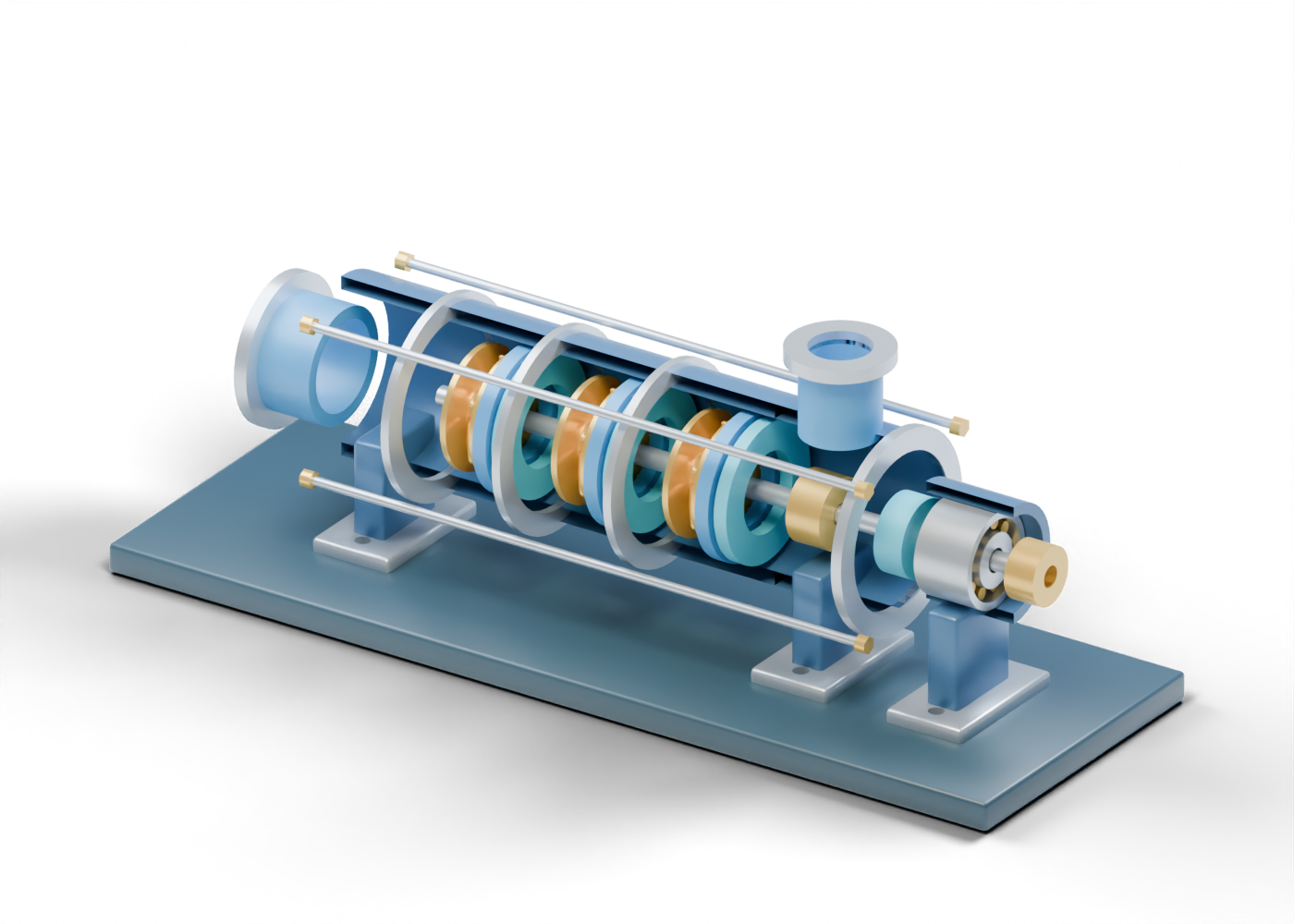
Pump display baseplate
Teaching support, not a foundation or alignment specification. Invented display proportions. No selected pump, product dimensions, flow, head, pressure, thrust, seal plan, material, driver, clearance, performance or service qualification.
Axial suction hollow neck
Open axial inlet role; no suction hydraulics. Invented display proportions. No selected pump, product dimensions, flow, head, pressure, thrust, seal plan, material, driver, clearance, performance or service qualification.
Suction bored flange
Unrated open flange marker. Invented display proportions. No selected pump, product dimensions, flow, head, pressure, thrust, seal plan, material, driver, clearance, performance or service qualification.
Complete suction casing wall
Complete hollow suction enclosure; the studio still alone removes its facing half. Invented display proportions. No selected pump, product dimensions, flow, head, pressure, thrust, seal plan, material, driver, clearance, performance or service qualification.
Stage 1 complete ring casing wall
Independent full annular stage enclosure. The still alone sections its facing half. Invented display proportions. No selected pump, product dimensions, flow, head, pressure, thrust, seal plan, material, driver, clearance, performance or service qualification.
Stage 1 joint ring
Visible stage joint location, not a rated joint. Invented display proportions. No selected pump, product dimensions, flow, head, pressure, thrust, seal plan, material, driver, clearance, performance or service qualification.
Stage 2 complete ring casing wall
Independent full annular stage enclosure. The still alone sections its facing half. Invented display proportions. No selected pump, product dimensions, flow, head, pressure, thrust, seal plan, material, driver, clearance, performance or service qualification.
Stage 2 joint ring
Visible stage joint location, not a rated joint. Invented display proportions. No selected pump, product dimensions, flow, head, pressure, thrust, seal plan, material, driver, clearance, performance or service qualification.
Stage 3 complete ring casing wall
Independent full annular stage enclosure. The still alone sections its facing half. Invented display proportions. No selected pump, product dimensions, flow, head, pressure, thrust, seal plan, material, driver, clearance, performance or service qualification.
Stage 3 joint ring
Visible stage joint location, not a rated joint. Invented display proportions. No selected pump, product dimensions, flow, head, pressure, thrust, seal plan, material, driver, clearance, performance or service qualification.
Complete discharge casing wall
Full hollow end casing with a real upper opening for the discharge neck; the studio still alone sections its facing half. Invented display proportions. No selected pump, product dimensions, flow, head, pressure, thrust, seal plan, material, driver, clearance, performance or service qualification.
Upper discharge hollow neck
Open upper discharge location; no piping or pressure rating. Invented display proportions. No selected pump, product dimensions, flow, head, pressure, thrust, seal plan, material, driver, clearance, performance or service qualification.
Upper discharge bored flange
Unrated bored flange marker. Invented display proportions. No selected pump, product dimensions, flow, head, pressure, thrust, seal plan, material, driver, clearance, performance or service qualification.
Drive end joint ring
End joint location only. Invented display proportions. No selected pump, product dimensions, flow, head, pressure, thrust, seal plan, material, driver, clearance, performance or service qualification.
Stage 1 impeller hub
Static rotating-region hub marker. Invented display proportions. No selected pump, product dimensions, flow, head, pressure, thrust, seal plan, material, driver, clearance, performance or service qualification.
Stage 1 front impeller shroud
Separate annular shroud; no selected clearance. Invented display proportions. No selected pump, product dimensions, flow, head, pressure, thrust, seal plan, material, driver, clearance, performance or service qualification.
Stage 1 back impeller shroud
Separate annular shroud; no selected clearance. Invented display proportions. No selected pump, product dimensions, flow, head, pressure, thrust, seal plan, material, driver, clearance, performance or service qualification.
Stage 1 curved impeller vane 1
Invented rotating-region fin, static in this illustration. Invented display proportions. No selected pump, product dimensions, flow, head, pressure, thrust, seal plan, material, driver, clearance, performance or service qualification.
Stage 1 curved impeller vane 2
Invented rotating-region fin, static in this illustration. Invented display proportions. No selected pump, product dimensions, flow, head, pressure, thrust, seal plan, material, driver, clearance, performance or service qualification.
Stage 1 curved impeller vane 3
Invented rotating-region fin, static in this illustration. Invented display proportions. No selected pump, product dimensions, flow, head, pressure, thrust, seal plan, material, driver, clearance, performance or service qualification.
Stage 1 curved impeller vane 4
Invented rotating-region fin, static in this illustration. Invented display proportions. No selected pump, product dimensions, flow, head, pressure, thrust, seal plan, material, driver, clearance, performance or service qualification.
Stage 1 curved impeller vane 5
Invented rotating-region fin, static in this illustration. Invented display proportions. No selected pump, product dimensions, flow, head, pressure, thrust, seal plan, material, driver, clearance, performance or service qualification.
Stage 1 curved impeller vane 6
Invented rotating-region fin, static in this illustration. Invented display proportions. No selected pump, product dimensions, flow, head, pressure, thrust, seal plan, material, driver, clearance, performance or service qualification.
Stage 1 diffuser carrier
Stationary diffuser location. Invented display proportions. No selected pump, product dimensions, flow, head, pressure, thrust, seal plan, material, driver, clearance, performance or service qualification.
Stage 1 diffuser vane 1
Static diffuser-region fin; no pressure-recovery claim. Invented display proportions. No selected pump, product dimensions, flow, head, pressure, thrust, seal plan, material, driver, clearance, performance or service qualification.
Stage 1 diffuser vane 2
Static diffuser-region fin; no pressure-recovery claim. Invented display proportions. No selected pump, product dimensions, flow, head, pressure, thrust, seal plan, material, driver, clearance, performance or service qualification.
Stage 1 diffuser vane 3
Static diffuser-region fin; no pressure-recovery claim. Invented display proportions. No selected pump, product dimensions, flow, head, pressure, thrust, seal plan, material, driver, clearance, performance or service qualification.
Stage 1 diffuser vane 4
Static diffuser-region fin; no pressure-recovery claim. Invented display proportions. No selected pump, product dimensions, flow, head, pressure, thrust, seal plan, material, driver, clearance, performance or service qualification.
Stage 1 diffuser vane 5
Static diffuser-region fin; no pressure-recovery claim. Invented display proportions. No selected pump, product dimensions, flow, head, pressure, thrust, seal plan, material, driver, clearance, performance or service qualification.
Stage 1 diffuser vane 6
Static diffuser-region fin; no pressure-recovery claim. Invented display proportions. No selected pump, product dimensions, flow, head, pressure, thrust, seal plan, material, driver, clearance, performance or service qualification.
Stage 1 return guide carrier
Separate return-guide location. Invented display proportions. No selected pump, product dimensions, flow, head, pressure, thrust, seal plan, material, driver, clearance, performance or service qualification.
Stage 1 return guide vane 1
Static return-path fin; no continuous fluid passage or measured flow. Invented display proportions. No selected pump, product dimensions, flow, head, pressure, thrust, seal plan, material, driver, clearance, performance or service qualification.
Stage 1 return guide vane 2
Static return-path fin; no continuous fluid passage or measured flow. Invented display proportions. No selected pump, product dimensions, flow, head, pressure, thrust, seal plan, material, driver, clearance, performance or service qualification.
Stage 1 return guide vane 3
Static return-path fin; no continuous fluid passage or measured flow. Invented display proportions. No selected pump, product dimensions, flow, head, pressure, thrust, seal plan, material, driver, clearance, performance or service qualification.
Stage 1 return guide vane 4
Static return-path fin; no continuous fluid passage or measured flow. Invented display proportions. No selected pump, product dimensions, flow, head, pressure, thrust, seal plan, material, driver, clearance, performance or service qualification.
Stage 1 return guide vane 5
Static return-path fin; no continuous fluid passage or measured flow. Invented display proportions. No selected pump, product dimensions, flow, head, pressure, thrust, seal plan, material, driver, clearance, performance or service qualification.
Stage 2 impeller hub
Static rotating-region hub marker. Invented display proportions. No selected pump, product dimensions, flow, head, pressure, thrust, seal plan, material, driver, clearance, performance or service qualification.
Stage 2 front impeller shroud
Separate annular shroud; no selected clearance. Invented display proportions. No selected pump, product dimensions, flow, head, pressure, thrust, seal plan, material, driver, clearance, performance or service qualification.
Stage 2 back impeller shroud
Separate annular shroud; no selected clearance. Invented display proportions. No selected pump, product dimensions, flow, head, pressure, thrust, seal plan, material, driver, clearance, performance or service qualification.
Stage 2 curved impeller vane 1
Invented rotating-region fin, static in this illustration. Invented display proportions. No selected pump, product dimensions, flow, head, pressure, thrust, seal plan, material, driver, clearance, performance or service qualification.
Stage 2 curved impeller vane 2
Invented rotating-region fin, static in this illustration. Invented display proportions. No selected pump, product dimensions, flow, head, pressure, thrust, seal plan, material, driver, clearance, performance or service qualification.
Stage 2 curved impeller vane 3
Invented rotating-region fin, static in this illustration. Invented display proportions. No selected pump, product dimensions, flow, head, pressure, thrust, seal plan, material, driver, clearance, performance or service qualification.
Stage 2 curved impeller vane 4
Invented rotating-region fin, static in this illustration. Invented display proportions. No selected pump, product dimensions, flow, head, pressure, thrust, seal plan, material, driver, clearance, performance or service qualification.
Stage 2 curved impeller vane 5
Invented rotating-region fin, static in this illustration. Invented display proportions. No selected pump, product dimensions, flow, head, pressure, thrust, seal plan, material, driver, clearance, performance or service qualification.
Stage 2 curved impeller vane 6
Invented rotating-region fin, static in this illustration. Invented display proportions. No selected pump, product dimensions, flow, head, pressure, thrust, seal plan, material, driver, clearance, performance or service qualification.
Stage 2 diffuser carrier
Stationary diffuser location. Invented display proportions. No selected pump, product dimensions, flow, head, pressure, thrust, seal plan, material, driver, clearance, performance or service qualification.
Stage 2 diffuser vane 1
Static diffuser-region fin; no pressure-recovery claim. Invented display proportions. No selected pump, product dimensions, flow, head, pressure, thrust, seal plan, material, driver, clearance, performance or service qualification.
Stage 2 diffuser vane 2
Static diffuser-region fin; no pressure-recovery claim. Invented display proportions. No selected pump, product dimensions, flow, head, pressure, thrust, seal plan, material, driver, clearance, performance or service qualification.
Stage 2 diffuser vane 3
Static diffuser-region fin; no pressure-recovery claim. Invented display proportions. No selected pump, product dimensions, flow, head, pressure, thrust, seal plan, material, driver, clearance, performance or service qualification.
Stage 2 diffuser vane 4
Static diffuser-region fin; no pressure-recovery claim. Invented display proportions. No selected pump, product dimensions, flow, head, pressure, thrust, seal plan, material, driver, clearance, performance or service qualification.
Stage 2 diffuser vane 5
Static diffuser-region fin; no pressure-recovery claim. Invented display proportions. No selected pump, product dimensions, flow, head, pressure, thrust, seal plan, material, driver, clearance, performance or service qualification.
Stage 2 diffuser vane 6
Static diffuser-region fin; no pressure-recovery claim. Invented display proportions. No selected pump, product dimensions, flow, head, pressure, thrust, seal plan, material, driver, clearance, performance or service qualification.
Stage 2 return guide carrier
Separate return-guide location. Invented display proportions. No selected pump, product dimensions, flow, head, pressure, thrust, seal plan, material, driver, clearance, performance or service qualification.
Stage 2 return guide vane 1
Static return-path fin; no continuous fluid passage or measured flow. Invented display proportions. No selected pump, product dimensions, flow, head, pressure, thrust, seal plan, material, driver, clearance, performance or service qualification.
Stage 2 return guide vane 2
Static return-path fin; no continuous fluid passage or measured flow. Invented display proportions. No selected pump, product dimensions, flow, head, pressure, thrust, seal plan, material, driver, clearance, performance or service qualification.
Stage 2 return guide vane 3
Static return-path fin; no continuous fluid passage or measured flow. Invented display proportions. No selected pump, product dimensions, flow, head, pressure, thrust, seal plan, material, driver, clearance, performance or service qualification.
Stage 2 return guide vane 4
Static return-path fin; no continuous fluid passage or measured flow. Invented display proportions. No selected pump, product dimensions, flow, head, pressure, thrust, seal plan, material, driver, clearance, performance or service qualification.
Stage 2 return guide vane 5
Static return-path fin; no continuous fluid passage or measured flow. Invented display proportions. No selected pump, product dimensions, flow, head, pressure, thrust, seal plan, material, driver, clearance, performance or service qualification.
Stage 3 impeller hub
Static rotating-region hub marker. Invented display proportions. No selected pump, product dimensions, flow, head, pressure, thrust, seal plan, material, driver, clearance, performance or service qualification.
Stage 3 front impeller shroud
Separate annular shroud; no selected clearance. Invented display proportions. No selected pump, product dimensions, flow, head, pressure, thrust, seal plan, material, driver, clearance, performance or service qualification.
Stage 3 back impeller shroud
Separate annular shroud; no selected clearance. Invented display proportions. No selected pump, product dimensions, flow, head, pressure, thrust, seal plan, material, driver, clearance, performance or service qualification.
Stage 3 curved impeller vane 1
Invented rotating-region fin, static in this illustration. Invented display proportions. No selected pump, product dimensions, flow, head, pressure, thrust, seal plan, material, driver, clearance, performance or service qualification.
Stage 3 curved impeller vane 2
Invented rotating-region fin, static in this illustration. Invented display proportions. No selected pump, product dimensions, flow, head, pressure, thrust, seal plan, material, driver, clearance, performance or service qualification.
Stage 3 curved impeller vane 3
Invented rotating-region fin, static in this illustration. Invented display proportions. No selected pump, product dimensions, flow, head, pressure, thrust, seal plan, material, driver, clearance, performance or service qualification.
Stage 3 curved impeller vane 4
Invented rotating-region fin, static in this illustration. Invented display proportions. No selected pump, product dimensions, flow, head, pressure, thrust, seal plan, material, driver, clearance, performance or service qualification.
Stage 3 curved impeller vane 5
Invented rotating-region fin, static in this illustration. Invented display proportions. No selected pump, product dimensions, flow, head, pressure, thrust, seal plan, material, driver, clearance, performance or service qualification.
Stage 3 curved impeller vane 6
Invented rotating-region fin, static in this illustration. Invented display proportions. No selected pump, product dimensions, flow, head, pressure, thrust, seal plan, material, driver, clearance, performance or service qualification.
Stage 3 diffuser carrier
Stationary diffuser location. Invented display proportions. No selected pump, product dimensions, flow, head, pressure, thrust, seal plan, material, driver, clearance, performance or service qualification.
Stage 3 diffuser vane 1
Static diffuser-region fin; no pressure-recovery claim. Invented display proportions. No selected pump, product dimensions, flow, head, pressure, thrust, seal plan, material, driver, clearance, performance or service qualification.
Stage 3 diffuser vane 2
Static diffuser-region fin; no pressure-recovery claim. Invented display proportions. No selected pump, product dimensions, flow, head, pressure, thrust, seal plan, material, driver, clearance, performance or service qualification.
Stage 3 diffuser vane 3
Static diffuser-region fin; no pressure-recovery claim. Invented display proportions. No selected pump, product dimensions, flow, head, pressure, thrust, seal plan, material, driver, clearance, performance or service qualification.
Stage 3 diffuser vane 4
Static diffuser-region fin; no pressure-recovery claim. Invented display proportions. No selected pump, product dimensions, flow, head, pressure, thrust, seal plan, material, driver, clearance, performance or service qualification.
Stage 3 diffuser vane 5
Static diffuser-region fin; no pressure-recovery claim. Invented display proportions. No selected pump, product dimensions, flow, head, pressure, thrust, seal plan, material, driver, clearance, performance or service qualification.
Stage 3 diffuser vane 6
Static diffuser-region fin; no pressure-recovery claim. Invented display proportions. No selected pump, product dimensions, flow, head, pressure, thrust, seal plan, material, driver, clearance, performance or service qualification.
Stage 3 return guide carrier
Separate return-guide location. Invented display proportions. No selected pump, product dimensions, flow, head, pressure, thrust, seal plan, material, driver, clearance, performance or service qualification.
Stage 3 return guide vane 1
Static return-path fin; no continuous fluid passage or measured flow. Invented display proportions. No selected pump, product dimensions, flow, head, pressure, thrust, seal plan, material, driver, clearance, performance or service qualification.
Stage 3 return guide vane 2
Static return-path fin; no continuous fluid passage or measured flow. Invented display proportions. No selected pump, product dimensions, flow, head, pressure, thrust, seal plan, material, driver, clearance, performance or service qualification.
Stage 3 return guide vane 3
Static return-path fin; no continuous fluid passage or measured flow. Invented display proportions. No selected pump, product dimensions, flow, head, pressure, thrust, seal plan, material, driver, clearance, performance or service qualification.
Stage 3 return guide vane 4
Static return-path fin; no continuous fluid passage or measured flow. Invented display proportions. No selected pump, product dimensions, flow, head, pressure, thrust, seal plan, material, driver, clearance, performance or service qualification.
Stage 3 return guide vane 5
Static return-path fin; no continuous fluid passage or measured flow. Invented display proportions. No selected pump, product dimensions, flow, head, pressure, thrust, seal plan, material, driver, clearance, performance or service qualification.
Common static shaft
Common axis through three display stages; no rotating or coupled-load simulation. Invented display proportions. No selected pump, product dimensions, flow, head, pressure, thrust, seal plan, material, driver, clearance, performance or service qualification.
Balance drum role marker
Annular balance-device location only; no thrust calculation. Invented display proportions. No selected pump, product dimensions, flow, head, pressure, thrust, seal plan, material, driver, clearance, performance or service qualification.
Drive end seal gland region
Seal location only; no seal faces, fluid barrier or plan. Invented display proportions. No selected pump, product dimensions, flow, head, pressure, thrust, seal plan, material, driver, clearance, performance or service qualification.
Bearing enclosure wall
Complete hollow bearing enclosure, not a selected bearing. Invented display proportions. No selected pump, product dimensions, flow, head, pressure, thrust, seal plan, material, driver, clearance, performance or service qualification.
Bearing inner ring cue
Independent inner-ring location. Invented display proportions. No selected pump, product dimensions, flow, head, pressure, thrust, seal plan, material, driver, clearance, performance or service qualification.
Bearing outer ring cue
Independent outer-ring location. Invented display proportions. No selected pump, product dimensions, flow, head, pressure, thrust, seal plan, material, driver, clearance, performance or service qualification.
Bearing roller cue 1
Static rolling-element location, not a bearing design. Invented display proportions. No selected pump, product dimensions, flow, head, pressure, thrust, seal plan, material, driver, clearance, performance or service qualification.
Bearing roller cue 2
Static rolling-element location, not a bearing design. Invented display proportions. No selected pump, product dimensions, flow, head, pressure, thrust, seal plan, material, driver, clearance, performance or service qualification.
Bearing roller cue 3
Static rolling-element location, not a bearing design. Invented display proportions. No selected pump, product dimensions, flow, head, pressure, thrust, seal plan, material, driver, clearance, performance or service qualification.
Bearing roller cue 4
Static rolling-element location, not a bearing design. Invented display proportions. No selected pump, product dimensions, flow, head, pressure, thrust, seal plan, material, driver, clearance, performance or service qualification.
Bearing roller cue 5
Static rolling-element location, not a bearing design. Invented display proportions. No selected pump, product dimensions, flow, head, pressure, thrust, seal plan, material, driver, clearance, performance or service qualification.
Bearing roller cue 6
Static rolling-element location, not a bearing design. Invented display proportions. No selected pump, product dimensions, flow, head, pressure, thrust, seal plan, material, driver, clearance, performance or service qualification.
Bearing roller cue 7
Static rolling-element location, not a bearing design. Invented display proportions. No selected pump, product dimensions, flow, head, pressure, thrust, seal plan, material, driver, clearance, performance or service qualification.
Bearing roller cue 8
Static rolling-element location, not a bearing design. Invented display proportions. No selected pump, product dimensions, flow, head, pressure, thrust, seal plan, material, driver, clearance, performance or service qualification.
Bearing roller cue 9
Static rolling-element location, not a bearing design. Invented display proportions. No selected pump, product dimensions, flow, head, pressure, thrust, seal plan, material, driver, clearance, performance or service qualification.
Bearing roller cue 10
Static rolling-element location, not a bearing design. Invented display proportions. No selected pump, product dimensions, flow, head, pressure, thrust, seal plan, material, driver, clearance, performance or service qualification.
Drive-side coupling hub cue
Unrated coupling location; no driver or guard. Invented display proportions. No selected pump, product dimensions, flow, head, pressure, thrust, seal plan, material, driver, clearance, performance or service qualification.
Casing tie rod 1
External static tie-rod location; no preload or pressure-boundary calculation. Invented display proportions. No selected pump, product dimensions, flow, head, pressure, thrust, seal plan, material, driver, clearance, performance or service qualification.
Casing tie rod 1 suction nut cue
Unrated fastening cue. Invented display proportions. No selected pump, product dimensions, flow, head, pressure, thrust, seal plan, material, driver, clearance, performance or service qualification.
Casing tie rod 1 drive nut cue
Unrated fastening cue. Invented display proportions. No selected pump, product dimensions, flow, head, pressure, thrust, seal plan, material, driver, clearance, performance or service qualification.
Casing tie rod 2
External static tie-rod location; no preload or pressure-boundary calculation. Invented display proportions. No selected pump, product dimensions, flow, head, pressure, thrust, seal plan, material, driver, clearance, performance or service qualification.
Casing tie rod 2 suction nut cue
Unrated fastening cue. Invented display proportions. No selected pump, product dimensions, flow, head, pressure, thrust, seal plan, material, driver, clearance, performance or service qualification.
Casing tie rod 2 drive nut cue
Unrated fastening cue. Invented display proportions. No selected pump, product dimensions, flow, head, pressure, thrust, seal plan, material, driver, clearance, performance or service qualification.
Casing tie rod 3
External static tie-rod location; no preload or pressure-boundary calculation. Invented display proportions. No selected pump, product dimensions, flow, head, pressure, thrust, seal plan, material, driver, clearance, performance or service qualification.
Casing tie rod 3 suction nut cue
Unrated fastening cue. Invented display proportions. No selected pump, product dimensions, flow, head, pressure, thrust, seal plan, material, driver, clearance, performance or service qualification.
Casing tie rod 3 drive nut cue
Unrated fastening cue. Invented display proportions. No selected pump, product dimensions, flow, head, pressure, thrust, seal plan, material, driver, clearance, performance or service qualification.
Casing tie rod 4
External static tie-rod location; no preload or pressure-boundary calculation. Invented display proportions. No selected pump, product dimensions, flow, head, pressure, thrust, seal plan, material, driver, clearance, performance or service qualification.
Casing tie rod 4 suction nut cue
Unrated fastening cue. Invented display proportions. No selected pump, product dimensions, flow, head, pressure, thrust, seal plan, material, driver, clearance, performance or service qualification.
Casing tie rod 4 drive nut cue
Unrated fastening cue. Invented display proportions. No selected pump, product dimensions, flow, head, pressure, thrust, seal plan, material, driver, clearance, performance or service qualification.
Pump support pedestal 1
Display support, not a structural foot. Invented display proportions. No selected pump, product dimensions, flow, head, pressure, thrust, seal plan, material, driver, clearance, performance or service qualification.
Pump bored foot 1
Bored display foot, not an installation design. Invented display proportions. No selected pump, product dimensions, flow, head, pressure, thrust, seal plan, material, driver, clearance, performance or service qualification.
Pump support pedestal 2
Display support, not a structural foot. Invented display proportions. No selected pump, product dimensions, flow, head, pressure, thrust, seal plan, material, driver, clearance, performance or service qualification.
Pump bored foot 2
Bored display foot, not an installation design. Invented display proportions. No selected pump, product dimensions, flow, head, pressure, thrust, seal plan, material, driver, clearance, performance or service qualification.
Pump support pedestal 3
Display support, not a structural foot. Invented display proportions. No selected pump, product dimensions, flow, head, pressure, thrust, seal plan, material, driver, clearance, performance or service qualification.
Pump bored foot 3
Bored display foot, not an installation design. Invented display proportions. No selected pump, product dimensions, flow, head, pressure, thrust, seal plan, material, driver, clearance, performance or service qualification.