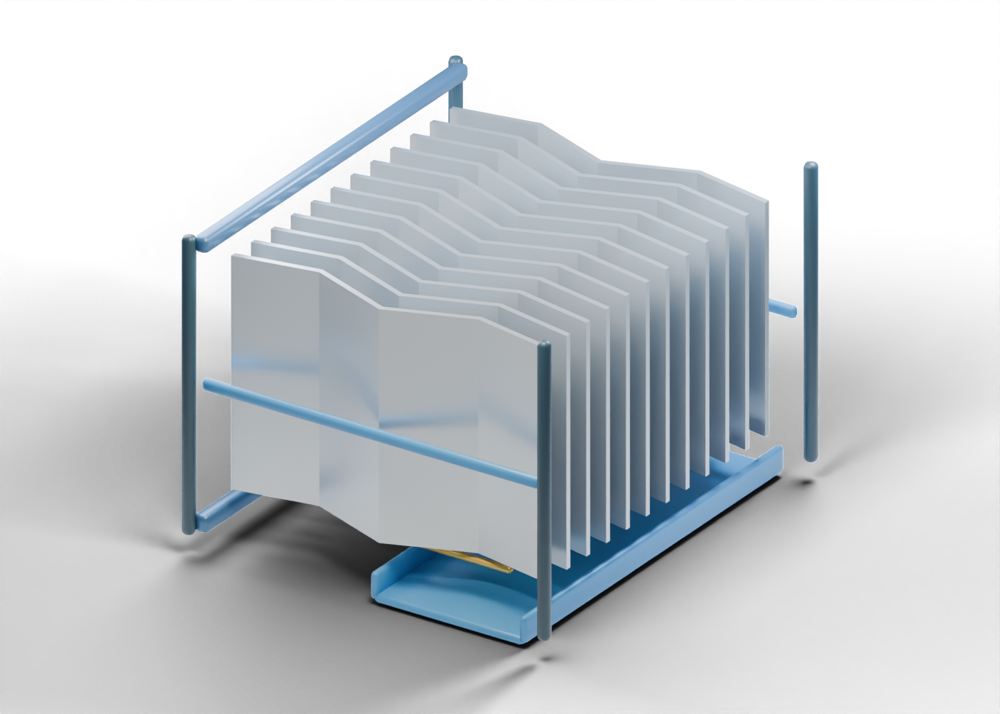
Lower module cross rail
Bottom structural reading boundary; no selected load or mounting detail. Invented static teaching geometry; no selected gas velocity, droplet size, removal efficiency, pressure drop, liquid load, fouling resistance, material, support calculation or service rating.
Upper module cross rail
Upper structural reading boundary; not a vessel attachment detail. Invented static teaching geometry; no selected gas velocity, droplet size, removal efficiency, pressure drop, liquid load, fouling resistance, material, support calculation or service rating.
Left side guide
Narrow outer frame edge; central gas passages stay open. Invented static teaching geometry; no selected gas velocity, droplet size, removal efficiency, pressure drop, liquid load, fouling resistance, material, support calculation or service rating.
Right side guide
Opposite outer frame edge; central gas passages stay open. Invented static teaching geometry; no selected gas velocity, droplet size, removal efficiency, pressure drop, liquid load, fouling resistance, material, support calculation or service rating.
Inlet left corner post
Separate frame corner marker, not an approved vessel support. Invented static teaching geometry; no selected gas velocity, droplet size, removal efficiency, pressure drop, liquid load, fouling resistance, material, support calculation or service rating.
Inlet right corner post
Separate frame corner marker, not an approved vessel support. Invented static teaching geometry; no selected gas velocity, droplet size, removal efficiency, pressure drop, liquid load, fouling resistance, material, support calculation or service rating.
Outlet left corner post
Separate frame corner marker, not an approved vessel support. Invented static teaching geometry; no selected gas velocity, droplet size, removal efficiency, pressure drop, liquid load, fouling resistance, material, support calculation or service rating.
Outlet right corner post
Separate frame corner marker, not an approved vessel support. Invented static teaching geometry; no selected gas velocity, droplet size, removal efficiency, pressure drop, liquid load, fouling resistance, material, support calculation or service rating.
Chevron vane 1
Independent full-height kinked vane with actual open adjacent gas passages. Invented static teaching geometry; no selected gas velocity, droplet size, removal efficiency, pressure drop, liquid load, fouling resistance, material, support calculation or service rating.
Vane 1 lower drainage lip
Separate lower lip location where collected liquid might be led away; not a hydraulic or re-entrainment prediction. Invented static teaching geometry; no selected gas velocity, droplet size, removal efficiency, pressure drop, liquid load, fouling resistance, material, support calculation or service rating.
Chevron vane 2
Independent full-height kinked vane with actual open adjacent gas passages. Invented static teaching geometry; no selected gas velocity, droplet size, removal efficiency, pressure drop, liquid load, fouling resistance, material, support calculation or service rating.
Vane 2 lower drainage lip
Separate lower lip location where collected liquid might be led away; not a hydraulic or re-entrainment prediction. Invented static teaching geometry; no selected gas velocity, droplet size, removal efficiency, pressure drop, liquid load, fouling resistance, material, support calculation or service rating.
Chevron vane 3
Independent full-height kinked vane with actual open adjacent gas passages. Invented static teaching geometry; no selected gas velocity, droplet size, removal efficiency, pressure drop, liquid load, fouling resistance, material, support calculation or service rating.
Vane 3 lower drainage lip
Separate lower lip location where collected liquid might be led away; not a hydraulic or re-entrainment prediction. Invented static teaching geometry; no selected gas velocity, droplet size, removal efficiency, pressure drop, liquid load, fouling resistance, material, support calculation or service rating.
Chevron vane 4
Independent full-height kinked vane with actual open adjacent gas passages. Invented static teaching geometry; no selected gas velocity, droplet size, removal efficiency, pressure drop, liquid load, fouling resistance, material, support calculation or service rating.
Vane 4 lower drainage lip
Separate lower lip location where collected liquid might be led away; not a hydraulic or re-entrainment prediction. Invented static teaching geometry; no selected gas velocity, droplet size, removal efficiency, pressure drop, liquid load, fouling resistance, material, support calculation or service rating.
Chevron vane 5
Independent full-height kinked vane with actual open adjacent gas passages. Invented static teaching geometry; no selected gas velocity, droplet size, removal efficiency, pressure drop, liquid load, fouling resistance, material, support calculation or service rating.
Vane 5 lower drainage lip
Separate lower lip location where collected liquid might be led away; not a hydraulic or re-entrainment prediction. Invented static teaching geometry; no selected gas velocity, droplet size, removal efficiency, pressure drop, liquid load, fouling resistance, material, support calculation or service rating.
Chevron vane 6
Independent full-height kinked vane with actual open adjacent gas passages. Invented static teaching geometry; no selected gas velocity, droplet size, removal efficiency, pressure drop, liquid load, fouling resistance, material, support calculation or service rating.
Vane 6 lower drainage lip
Separate lower lip location where collected liquid might be led away; not a hydraulic or re-entrainment prediction. Invented static teaching geometry; no selected gas velocity, droplet size, removal efficiency, pressure drop, liquid load, fouling resistance, material, support calculation or service rating.
Chevron vane 7
Independent full-height kinked vane with actual open adjacent gas passages. Invented static teaching geometry; no selected gas velocity, droplet size, removal efficiency, pressure drop, liquid load, fouling resistance, material, support calculation or service rating.
Vane 7 lower drainage lip
Separate lower lip location where collected liquid might be led away; not a hydraulic or re-entrainment prediction. Invented static teaching geometry; no selected gas velocity, droplet size, removal efficiency, pressure drop, liquid load, fouling resistance, material, support calculation or service rating.
Chevron vane 8
Independent full-height kinked vane with actual open adjacent gas passages. Invented static teaching geometry; no selected gas velocity, droplet size, removal efficiency, pressure drop, liquid load, fouling resistance, material, support calculation or service rating.
Vane 8 lower drainage lip
Separate lower lip location where collected liquid might be led away; not a hydraulic or re-entrainment prediction. Invented static teaching geometry; no selected gas velocity, droplet size, removal efficiency, pressure drop, liquid load, fouling resistance, material, support calculation or service rating.
Chevron vane 9
Independent full-height kinked vane with actual open adjacent gas passages. Invented static teaching geometry; no selected gas velocity, droplet size, removal efficiency, pressure drop, liquid load, fouling resistance, material, support calculation or service rating.
Vane 9 lower drainage lip
Separate lower lip location where collected liquid might be led away; not a hydraulic or re-entrainment prediction. Invented static teaching geometry; no selected gas velocity, droplet size, removal efficiency, pressure drop, liquid load, fouling resistance, material, support calculation or service rating.
Chevron vane 10
Independent full-height kinked vane with actual open adjacent gas passages. Invented static teaching geometry; no selected gas velocity, droplet size, removal efficiency, pressure drop, liquid load, fouling resistance, material, support calculation or service rating.
Vane 10 lower drainage lip
Separate lower lip location where collected liquid might be led away; not a hydraulic or re-entrainment prediction. Invented static teaching geometry; no selected gas velocity, droplet size, removal efficiency, pressure drop, liquid load, fouling resistance, material, support calculation or service rating.
Chevron vane 11
Independent full-height kinked vane with actual open adjacent gas passages. Invented static teaching geometry; no selected gas velocity, droplet size, removal efficiency, pressure drop, liquid load, fouling resistance, material, support calculation or service rating.
Vane 11 lower drainage lip
Separate lower lip location where collected liquid might be led away; not a hydraulic or re-entrainment prediction. Invented static teaching geometry; no selected gas velocity, droplet size, removal efficiency, pressure drop, liquid load, fouling resistance, material, support calculation or service rating.
Chevron vane 12
Independent full-height kinked vane with actual open adjacent gas passages. Invented static teaching geometry; no selected gas velocity, droplet size, removal efficiency, pressure drop, liquid load, fouling resistance, material, support calculation or service rating.
Vane 12 lower drainage lip
Separate lower lip location where collected liquid might be led away; not a hydraulic or re-entrainment prediction. Invented static teaching geometry; no selected gas velocity, droplet size, removal efficiency, pressure drop, liquid load, fouling resistance, material, support calculation or service rating.
Lower collection trough floor
Illustrative lower collection location beneath the separate vane lips. Invented static teaching geometry; no selected gas velocity, droplet size, removal efficiency, pressure drop, liquid load, fouling resistance, material, support calculation or service rating.
Lower collection trough inlet rim
One separate wall of the open lower collection trough. Invented static teaching geometry; no selected gas velocity, droplet size, removal efficiency, pressure drop, liquid load, fouling resistance, material, support calculation or service rating.
Lower collection trough outlet rim
Opposite separate wall of the open lower collection trough. Invented static teaching geometry; no selected gas velocity, droplet size, removal efficiency, pressure drop, liquid load, fouling resistance, material, support calculation or service rating.