
PROCESS PLANTS / SIX STOPS / ORIGINAL 3D
Read a fractionation column.
Follow the visible boundaries. Question the product claim.
Six guided questions through an original trayed-column illustration: mixed-liquid feed, deck openings, downcomers, bottom heat, overhead handling and the evidence needed for a real product claim.
This invented, static NGL column is an introductory illustration. It is not a named Alberta facility, an engineered process, a product assay, an operating guide or a training credential.
ONE COLUMN / OPEN PROCESS BOUNDARIES
See the roles without inventing the plant.
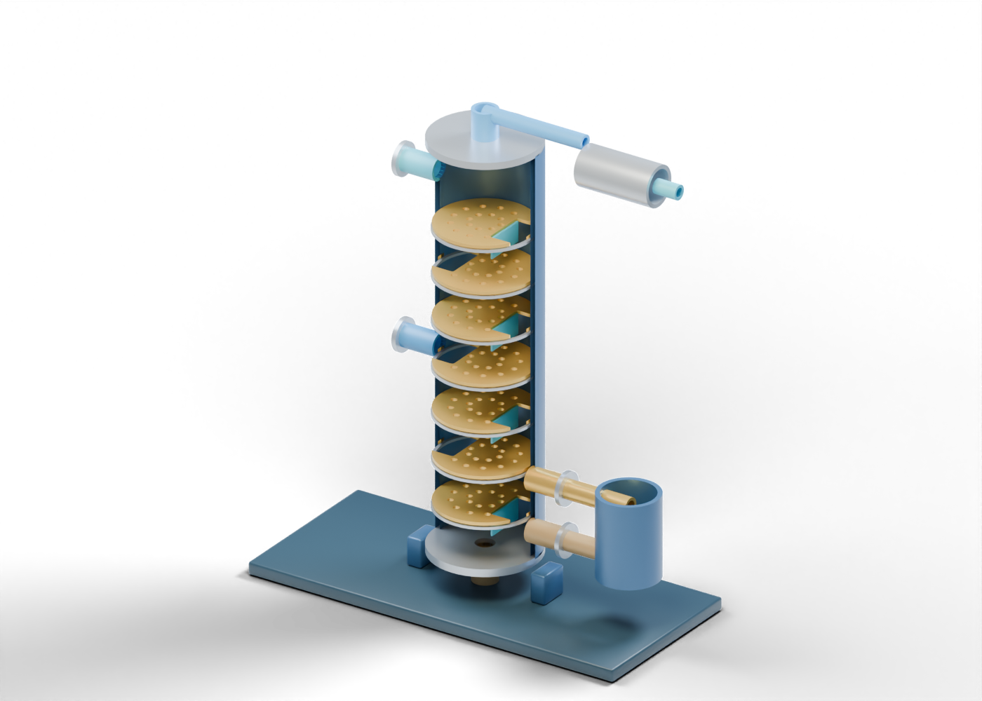
Use this text map even without 3D. The separate heat-exchange envelopes and open product ends explain questions to ask; they are not a connected design.
Inside the shell
Perforated contact decks ↔ alternating downcomer openings
Bottom question
Reboiler role ↔ column; open heavier-product boundary
Overhead question
Vapour boundary → cooling role; separate reflux-return cue
No selected product cut, accumulator, complete pipe circuit, measured purity or actual facility is shown.
STUDY 01 / 06
Start with the mixed-liquid feed
Distinguish the incoming NGL mixture from the product the column is meant to recover.
The U.S. Energy Information Administration describes mixed natural-gas liquids leaving processing as a stream that can be separated into component products by fractionation. The original blue feed neck simply identifies where an incoming stream might meet a column.
Its height and size were invented for this illustration. A real feed composition, rate, condition and chosen product cut must come from project records, not from the picture.
PAUSE AND EXPLAIN
Does the visible feed nozzle identify a real plant's mixture or capacity?
Reveal the explanation
No. It marks an illustrative boundary. Composition, conditions and capacity require attributable design or operating evidence.
STUDY 02 / 06
Look through a tray deck
Recognize a contact-region role without treating the geometric holes as a tested tray.
Sulzer describes trayed columns as one way to bring rising vapour and liquid into contact. The fourth gold deck has twenty genuine holes in the 3D mesh, large enough to inspect individually.
The hole pattern, deck count and spacing are original display choices. They cannot establish liquid holdup, vapour traffic, mass transfer, flooding margin or product purity.
PAUSE AND EXPLAIN
What can the perforations prove?
Reveal the explanation
Only that the illustrated mesh has open passages. They do not measure separation or show a qualified tray design.
STUDY 03 / 06
Compare the liquid-transfer openings
Follow the alternation between neighbouring decks while keeping the static model separate from liquid motion.
The fourth and fifth decks have openings on opposite sides. Independent blue partition cues help show where downward liquid transfer can be discussed in a trayed-column lesson.
This model contains no liquid film, measured level or functioning weir. The openings do not establish a continuous hydraulic path or a suitable tray arrangement for any NGL service.
PAUSE AND EXPLAIN
Does an alternating opening establish the liquid flow rate?
Reveal the explanation
No. It illustrates a possible transfer role; actual hydraulics depend on a designed, tested arrangement and operating data.
STUDY 04 / 06
Ask what the bottom heat does
Separate a reboiler's process role from the external hardware pictured beside the column.
Emerson's oil and gas sourcebook describes reboiler heat helping return vapour to a fractionation tower while heavier material continues toward a bottoms stream. This blue external cylinder and two open branches mark that role only.
The scene does not select a heating utility, exchanger type, duty, circulation arrangement or temperature. Its lower outlet is an open heavier-product boundary, not a measured specification.
PAUSE AND EXPLAIN
Can the drawn reboiler establish heat duty or bottoms composition?
Reveal the explanation
No. Both require actual process data and qualified design or measurement.
STUDY 05 / 06
Stop at the overhead and reflux boundaries
See where cooling and liquid return belong conceptually, and where this illustration deliberately ends.
The overhead neck, cooling-role envelope and upper reflux return cue are separate parts. Emerson describes an overhead condenser and reflux accumulator in a typical NGL fractionation sequence; some condensed liquid can return as reflux.
No accumulator, pump, split, utility or continuous engineered pipe circuit is modeled here. The silver envelope does not establish that all overhead material condenses or that a particular product is recovered.
PAUSE AND EXPLAIN
What is missing before calling the pictured overhead a product stream?
Reveal the explanation
A selected separation scheme, actual overhead handling and attributable product-composition evidence.
STUDY 06 / 06
Test a real product claim
Use the visible equipment to ask for dates, streams and measurement instead of inferring them.
A deethanizer, depropanizer and debutanizer have different intended cuts in Emerson's example sequence. This illustration selects none of them. EIA's product categories help name possible outputs, but do not identify any Alberta facility or its performance.
For a named plant, identify its operator and location, the dated feed and product records, the actual process arrangement and the evidence behind any purity, capacity or emissions claim. The original 3D scene supplies component vocabulary, not those results.
PAUSE AND EXPLAIN
What would support a named facility's product-purity claim?
Reveal the explanation
Attributable, dated sampling or operating records for that facility and product. A generic model cannot supply them.
Ask what the illustration cannot tell you.
The model gives names to visible parts. A product, capacity or emissions claim needs attributable records from an actual facility.
| Role | Visible cue | Evidence question | What this model lacks |
|---|---|---|---|
| Feed | Open mixed-NGL neck | What mixture, date, source and conditions enter the actual column? | No composition, rate or feed condition |
| Contact region | Seven perforated decks and alternating gaps | Which installed internals and performance records support the claimed cut? | No tray rating, hydraulics or mass-transfer result |
| Heat and reflux | Reboiler and condenser role envelopes | What real utility, duty, accumulator and return scheme are documented? | No complete thermal or pipe circuit |
| Products | Open overhead and bottoms boundaries | Which dated samples or meters establish each product and destination? | No product purity, capacity or sales evidence |
Keep the source beside the picture.
References checked 2026-09-29. They support general process vocabulary, not this model's geometry or any installed facility.
- U.S. EIA — Where do hydrocarbon gas liquids come from? ↗
Mixed NGL stream and fractionation into component products; U.S. context, not an Alberta facility claim.
- Emerson — Control Valve Sourcebook: Oil and Gas ↗
Example deethanizer/depropanizer/debutanizer, condenser, reflux and reboiler roles; no drawing, dimensions or operating values adopted.
- Sulzer — Distillation technology ↗
General vapour–liquid contacting, trays and heat-exchange roles; no vendor tray geometry copied.