Base frame
Illustrative support frame; foundations and structural design vary.
Liquid knock-out drum / Dished closure 1
Generic double-surface dished closure. Shape and thickness are illustrative, with no code qualification. Reused at an invented scale and location; no equipment matching, protection or field selection is implied.
Liquid knock-out drum / Dished closure -1
Generic double-surface dished closure. Shape and thickness are illustrative, with no code qualification. Reused at an invented scale and location; no equipment matching, protection or field selection is implied.
Liquid knock-out drum / External gas-path arrow head
Static reading arrow outside the vessel. Original invented teaching geometry; no design, rating, liquid-removal performance, flare safety or service qualification. Reused at an invented scale and location; no equipment matching, protection or field selection is implied.
Liquid knock-out drum / External gas-path arrow shaft
Reading direction only; no actual velocity, combustion or gas flow. Original invented teaching geometry; no design, rating, liquid-removal performance, flare safety or service qualification. Reused at an invented scale and location; no equipment matching, protection or field selection is implied.
Liquid knock-out drum / Gas outlet bored end collar
Separate open collar without a rated face, gasket or matched pipe. Original invented teaching geometry; no design, rating, liquid-removal performance, flare safety or service qualification. Reused at an invented scale and location; no equipment matching, protection or field selection is implied.
Liquid knock-out drum / Gas outlet hollow neck
Open boundary at the drilled wall. No selected connection, instrument or destination. Original invented teaching geometry; no design, rating, liquid-removal performance, flare safety or service qualification. Reused at an invented scale and location; no equipment matching, protection or field selection is implied.
Liquid knock-out drum / Head seam marker 1
Illustrative junction location, without weld design. Original invented teaching geometry; no design, rating, liquid-removal performance, flare safety or service qualification. Reused at an invented scale and location; no equipment matching, protection or field selection is implied.
Liquid knock-out drum / Head seam marker -1
Illustrative junction location, without weld design. Original invented teaching geometry; no design, rating, liquid-removal performance, flare safety or service qualification. Reused at an invented scale and location; no equipment matching, protection or field selection is implied.
Liquid knock-out drum / Header inlet bored end collar
Separate open collar without a rated face, gasket or matched pipe. Original invented teaching geometry; no design, rating, liquid-removal performance, flare safety or service qualification. Reused at an invented scale and location; no equipment matching, protection or field selection is implied.
Liquid knock-out drum / Header inlet hollow neck
Open boundary at the drilled wall. No selected connection, instrument or destination. Original invented teaching geometry; no design, rating, liquid-removal performance, flare safety or service qualification. Reused at an invented scale and location; no equipment matching, protection or field selection is implied.
Liquid knock-out drum / Illustrative liquid-region plane
Static colour boundary only. It is not actual liquid, capacity or a live gauge. Original invented teaching geometry; no design, rating, liquid-removal performance, flare safety or service qualification. Reused at an invented scale and location; no equipment matching, protection or field selection is implied.
Liquid knock-out drum / Inlet impact plate
Independent splash/impact location. No selected baffle, strength or droplet-removal performance. Original invented teaching geometry; no design, rating, liquid-removal performance, flare safety or service qualification. Reused at an invented scale and location; no equipment matching, protection or field selection is implied.
Liquid knock-out drum / Inlet plate standoff 1
Geometric location marker without weld, load or material specification. Original invented teaching geometry; no design, rating, liquid-removal performance, flare safety or service qualification. Reused at an invented scale and location; no equipment matching, protection or field selection is implied.
Liquid knock-out drum / Inlet plate standoff 2
Geometric location marker without weld, load or material specification. Original invented teaching geometry; no design, rating, liquid-removal performance, flare safety or service qualification. Reused at an invented scale and location; no equipment matching, protection or field selection is implied.
Liquid knock-out drum / Inlet plate standoff 3
Geometric location marker without weld, load or material specification. Original invented teaching geometry; no design, rating, liquid-removal performance, flare safety or service qualification. Reused at an invented scale and location; no equipment matching, protection or field selection is implied.
Liquid knock-out drum / Knock-out drum hollow shell
Separate outer and inner cylindrical surfaces with real wall openings. Original invented teaching geometry; no design, rating, liquid-removal performance, flare safety or service qualification. Reused at an invented scale and location; no equipment matching, protection or field selection is implied.
Liquid knock-out drum / Liquid collection outlet bored end collar
Separate open collar without a rated face, gasket or matched pipe. Original invented teaching geometry; no design, rating, liquid-removal performance, flare safety or service qualification. Reused at an invented scale and location; no equipment matching, protection or field selection is implied.
Liquid knock-out drum / Liquid collection outlet hollow neck
Open boundary at the drilled wall. No selected connection, instrument or destination. Original invented teaching geometry; no design, rating, liquid-removal performance, flare safety or service qualification. Reused at an invented scale and location; no equipment matching, protection or field selection is implied.
Liquid knock-out drum / Lower level boundary bored end collar
Separate open collar without a rated face, gasket or matched pipe. Original invented teaching geometry; no design, rating, liquid-removal performance, flare safety or service qualification. Reused at an invented scale and location; no equipment matching, protection or field selection is implied.
Liquid knock-out drum / Lower level boundary hollow neck
Open boundary at the drilled wall. No selected connection, instrument or destination. Original invented teaching geometry; no design, rating, liquid-removal performance, flare safety or service qualification. Reused at an invented scale and location; no equipment matching, protection or field selection is implied.
Liquid knock-out drum / Support 2.03 anchor 1 smooth rod
Location marker; no embedded anchor or clamp load. Original invented teaching geometry; no design, rating, liquid-removal performance, flare safety or service qualification. Reused at an invented scale and location; no equipment matching, protection or field selection is implied.
Liquid knock-out drum / Support 2.03 anchor 1 washer
Independent annular washer location. Original invented teaching geometry; no design, rating, liquid-removal performance, flare safety or service qualification. Reused at an invented scale and location; no equipment matching, protection or field selection is implied.
Liquid knock-out drum / Support 2.03 anchor 2 smooth rod
Location marker; no embedded anchor or clamp load. Original invented teaching geometry; no design, rating, liquid-removal performance, flare safety or service qualification. Reused at an invented scale and location; no equipment matching, protection or field selection is implied.
Liquid knock-out drum / Support 2.03 anchor 2 washer
Independent annular washer location. Original invented teaching geometry; no design, rating, liquid-removal performance, flare safety or service qualification. Reused at an invented scale and location; no equipment matching, protection or field selection is implied.
Liquid knock-out drum / Support -2.03 anchor 1 smooth rod
Location marker; no embedded anchor or clamp load. Original invented teaching geometry; no design, rating, liquid-removal performance, flare safety or service qualification. Reused at an invented scale and location; no equipment matching, protection or field selection is implied.
Liquid knock-out drum / Support -2.03 anchor 1 washer
Independent annular washer location. Original invented teaching geometry; no design, rating, liquid-removal performance, flare safety or service qualification. Reused at an invented scale and location; no equipment matching, protection or field selection is implied.
Liquid knock-out drum / Support -2.03 anchor 2 smooth rod
Location marker; no embedded anchor or clamp load. Original invented teaching geometry; no design, rating, liquid-removal performance, flare safety or service qualification. Reused at an invented scale and location; no equipment matching, protection or field selection is implied.
Liquid knock-out drum / Support -2.03 anchor 2 washer
Independent annular washer location. Original invented teaching geometry; no design, rating, liquid-removal performance, flare safety or service qualification. Reused at an invented scale and location; no equipment matching, protection or field selection is implied.
Liquid knock-out drum / Support foot 2.03
Base location with two true anchor openings. Original invented teaching geometry; no design, rating, liquid-removal performance, flare safety or service qualification. Reused at an invented scale and location; no equipment matching, protection or field selection is implied.
Liquid knock-out drum / Support foot -2.03
Base location with two true anchor openings. Original invented teaching geometry; no design, rating, liquid-removal performance, flare safety or service qualification. Reused at an invented scale and location; no equipment matching, protection or field selection is implied.
Liquid knock-out drum / Upper level boundary bored end collar
Separate open collar without a rated face, gasket or matched pipe. Original invented teaching geometry; no design, rating, liquid-removal performance, flare safety or service qualification. Reused at an invented scale and location; no equipment matching, protection or field selection is implied.
Liquid knock-out drum / Upper level boundary hollow neck
Open boundary at the drilled wall. No selected connection, instrument or destination. Original invented teaching geometry; no design, rating, liquid-removal performance, flare safety or service qualification. Reused at an invented scale and location; no equipment matching, protection or field selection is implied.
Liquid knock-out drum / Vessel support saddle 2.03
Separate support location without load or foundation design. Original invented teaching geometry; no design, rating, liquid-removal performance, flare safety or service qualification. Reused at an invented scale and location; no equipment matching, protection or field selection is implied.
Liquid knock-out drum / Vessel support saddle -2.03
Separate support location without load or foundation design. Original invented teaching geometry; no design, rating, liquid-removal performance, flare safety or service qualification. Reused at an invented scale and location; no equipment matching, protection or field selection is implied.
Illustrative liquid-seal drum / Bent inlet and submerged leg
One open tube enters from the header side and turns downward below the static blue surface. The illustrated immersion does not establish a functioning seal. Invented educational geometry only; no selected liquid head, gas duty, pressure rating, flashback protection or operating instruction. Reused at an invented scale and location; no equipment matching, protection or field selection is implied.
Illustrative liquid-seal drum / Downstream gas outlet neck
Open upper destination toward downstream flare equipment, which is not modeled. Invented educational geometry only; no selected liquid head, gas duty, pressure rating, flashback protection or operating instruction. Reused at an invented scale and location; no equipment matching, protection or field selection is implied.
Illustrative liquid-seal drum / Downstream outlet collar
Unrated open boundary marker; no connected stack, purge or flare tip. Invented educational geometry only; no selected liquid head, gas duty, pressure rating, flashback protection or operating instruction. Reused at an invented scale and location; no equipment matching, protection or field selection is implied.
Illustrative liquid-seal drum / Drain outlet collar
Unrated annular drain boundary; no disposal or closed valve is shown. Invented educational geometry only; no selected liquid head, gas duty, pressure rating, flashback protection or operating instruction. Reused at an invented scale and location; no equipment matching, protection or field selection is implied.
Illustrative liquid-seal drum / External reading arrow head
Static downstream-direction marker outside the vessel. Invented educational geometry only; no selected liquid head, gas duty, pressure rating, flashback protection or operating instruction. Reused at an invented scale and location; no equipment matching, protection or field selection is implied.
Illustrative liquid-seal drum / External reading arrow shaft
Static reading direction outside the vessel; not a gas velocity or operating state. Invented educational geometry only; no selected liquid head, gas duty, pressure rating, flashback protection or operating instruction. Reused at an invented scale and location; no equipment matching, protection or field selection is implied.
Illustrative liquid-seal drum / Header-side inlet collar
Open connection boundary; upstream knock-out drum and header are outside this model. Invented educational geometry only; no selected liquid head, gas duty, pressure rating, flashback protection or operating instruction. Reused at an invented scale and location; no equipment matching, protection or field selection is implied.
Illustrative liquid-seal drum / Illustrative liquid surface
Static reading plane. It is not water inventory, a measured level, calculated liquid head or proof of a protective seal. Invented educational geometry only; no selected liquid head, gas duty, pressure rating, flashback protection or operating instruction. Reused at an invented scale and location; no equipment matching, protection or field selection is implied.
Illustrative liquid-seal drum / Liquid surface edge marker
Circular level-reading marker at an arbitrary height. Invented educational geometry only; no selected liquid head, gas duty, pressure rating, flashback protection or operating instruction. Reused at an invented scale and location; no equipment matching, protection or field selection is implied.
Illustrative liquid-seal drum / Lower level boundary collar
Separate bored connection marker, without a rated joint. Invented educational geometry only; no selected liquid head, gas duty, pressure rating, flashback protection or operating instruction. Reused at an invented scale and location; no equipment matching, protection or field selection is implied.
Illustrative liquid-seal drum / Lower level boundary neck
Open instrument connection location without a gauge, control logic or setpoint. Invented educational geometry only; no selected liquid head, gas duty, pressure rating, flashback protection or operating instruction. Reused at an invented scale and location; no equipment matching, protection or field selection is implied.
Illustrative liquid-seal drum / Lower liquid drain neck
Open liquid-removal boundary. Storage, treatment and controls are outside the model. Invented educational geometry only; no selected liquid head, gas duty, pressure rating, flashback protection or operating instruction. Reused at an invented scale and location; no equipment matching, protection or field selection is implied.
Illustrative liquid-seal drum / Lower shell seam marker
Visible junction marker, not a weld or inspection record. Invented educational geometry only; no selected liquid head, gas duty, pressure rating, flashback protection or operating instruction. Reused at an invented scale and location; no equipment matching, protection or field selection is implied.
Illustrative liquid-seal drum / Lower vessel closure
Lower enclosing plate with a real drain opening. Invented educational geometry only; no selected liquid head, gas duty, pressure rating, flashback protection or operating instruction. Reused at an invented scale and location; no equipment matching, protection or field selection is implied.
Illustrative liquid-seal drum / Seal-vessel hollow wall
Vertical open-ended shell with actual side passages. Invented educational geometry only; no selected liquid head, gas duty, pressure rating, flashback protection or operating instruction. Reused at an invented scale and location; no equipment matching, protection or field selection is implied.
Illustrative liquid-seal drum / Submerged leg outlet ring
Separate open end marker inside the liquid region; no bubble, backflow or pressure behaviour is simulated. Invented educational geometry only; no selected liquid head, gas duty, pressure rating, flashback protection or operating instruction. Reused at an invented scale and location; no equipment matching, protection or field selection is implied.
Illustrative liquid-seal drum / Support foot +0.68 +0.68
Foot with a geometric anchor opening; no fastener specification. Invented educational geometry only; no selected liquid head, gas duty, pressure rating, flashback protection or operating instruction. Reused at an invented scale and location; no equipment matching, protection or field selection is implied.
Illustrative liquid-seal drum / Support foot +0.68 -0.68
Foot with a geometric anchor opening; no fastener specification. Invented educational geometry only; no selected liquid head, gas duty, pressure rating, flashback protection or operating instruction. Reused at an invented scale and location; no equipment matching, protection or field selection is implied.
Illustrative liquid-seal drum / Support foot -0.68 +0.68
Foot with a geometric anchor opening; no fastener specification. Invented educational geometry only; no selected liquid head, gas duty, pressure rating, flashback protection or operating instruction. Reused at an invented scale and location; no equipment matching, protection or field selection is implied.
Illustrative liquid-seal drum / Support foot -0.68 -0.68
Foot with a geometric anchor opening; no fastener specification. Invented educational geometry only; no selected liquid head, gas duty, pressure rating, flashback protection or operating instruction. Reused at an invented scale and location; no equipment matching, protection or field selection is implied.
Illustrative liquid-seal drum / Support leg +0.68 +0.68
Independent support position without structural or foundation design. Invented educational geometry only; no selected liquid head, gas duty, pressure rating, flashback protection or operating instruction. Reused at an invented scale and location; no equipment matching, protection or field selection is implied.
Illustrative liquid-seal drum / Support leg +0.68 -0.68
Independent support position without structural or foundation design. Invented educational geometry only; no selected liquid head, gas duty, pressure rating, flashback protection or operating instruction. Reused at an invented scale and location; no equipment matching, protection or field selection is implied.
Illustrative liquid-seal drum / Support leg -0.68 +0.68
Independent support position without structural or foundation design. Invented educational geometry only; no selected liquid head, gas duty, pressure rating, flashback protection or operating instruction. Reused at an invented scale and location; no equipment matching, protection or field selection is implied.
Illustrative liquid-seal drum / Support leg -0.68 -0.68
Independent support position without structural or foundation design. Invented educational geometry only; no selected liquid head, gas duty, pressure rating, flashback protection or operating instruction. Reused at an invented scale and location; no equipment matching, protection or field selection is implied.
Illustrative liquid-seal drum / Upper level boundary collar
Separate bored connection marker, without a rated joint. Invented educational geometry only; no selected liquid head, gas duty, pressure rating, flashback protection or operating instruction. Reused at an invented scale and location; no equipment matching, protection or field selection is implied.
Illustrative liquid-seal drum / Upper level boundary neck
Open instrument connection location without a gauge, control logic or setpoint. Invented educational geometry only; no selected liquid head, gas duty, pressure rating, flashback protection or operating instruction. Reused at an invented scale and location; no equipment matching, protection or field selection is implied.
Illustrative liquid-seal drum / Upper shell seam marker
Visible junction marker, not a weld or inspection record. Invented educational geometry only; no selected liquid head, gas duty, pressure rating, flashback protection or operating instruction. Reused at an invented scale and location; no equipment matching, protection or field selection is implied.
Illustrative liquid-seal drum / Upper vessel closure
Upper enclosing plate with a real outlet opening. Invented educational geometry only; no selected liquid head, gas duty, pressure rating, flashback protection or operating instruction. Reused at an invented scale and location; no equipment matching, protection or field selection is implied.
Stack foundation marker
Visible base location only; foundations and loads are outside the lesson. Invented teaching geometry. No stack rating, hydraulic design, flame stability, pilot/ignition system, purge, gas seal, structural design, emissions result or operating instruction.
Hollow lower stack barrel
Open cylindrical lower wall with a real side inlet bore. Invented teaching geometry. No stack rating, hydraulic design, flame stability, pilot/ignition system, purge, gas seal, structural design, emissions result or operating instruction.
Hollow upper stack barrel
Separate open-ended upper wall; gas seal and internal hardware are omitted. Invented teaching geometry. No stack rating, hydraulic design, flame stability, pilot/ignition system, purge, gas seal, structural design, emissions result or operating instruction.
Header-side open stack inlet
Hollow side boundary meeting the lower wall bore. Invented teaching geometry. No stack rating, hydraulic design, flame stability, pilot/ignition system, purge, gas seal, structural design, emissions result or operating instruction.
Open stack collar 4.25
Annular open marker; no welded joint, pressure class or burner design. Invented teaching geometry. No stack rating, hydraulic design, flame stability, pilot/ignition system, purge, gas seal, structural design, emissions result or operating instruction.
Open stack collar 8.55
Annular open marker; no welded joint, pressure class or burner design. Invented teaching geometry. No stack rating, hydraulic design, flame stability, pilot/ignition system, purge, gas seal, structural design, emissions result or operating instruction.
Open tip location
Open elevated location only; no flame, combustion efficiency or plume is depicted. Invented teaching geometry. No stack rating, hydraulic design, flame stability, pilot/ignition system, purge, gas seal, structural design, emissions result or operating instruction.
Pilot-location envelope left
Open marker for a possible pilot position; no pilot burner, fuel, ignition, monitoring or operation. Invented teaching geometry. No stack rating, hydraulic design, flame stability, pilot/ignition system, purge, gas seal, structural design, emissions result or operating instruction.
Pilot-location support left
Schematic marker support, not a fabricated bracket. Invented teaching geometry. No stack rating, hydraulic design, flame stability, pilot/ignition system, purge, gas seal, structural design, emissions result or operating instruction.
Pilot-location envelope right
Open marker for a possible pilot position; no pilot burner, fuel, ignition, monitoring or operation. Invented teaching geometry. No stack rating, hydraulic design, flame stability, pilot/ignition system, purge, gas seal, structural design, emissions result or operating instruction.
Pilot-location support right
Schematic marker support, not a fabricated bracket. Invented teaching geometry. No stack rating, hydraulic design, flame stability, pilot/ignition system, purge, gas seal, structural design, emissions result or operating instruction.
Lower stack support marker -1
Schematic base marker without structural or anchor calculation. Invented teaching geometry. No stack rating, hydraulic design, flame stability, pilot/ignition system, purge, gas seal, structural design, emissions result or operating instruction.
Lower stack support marker 1
Schematic base marker without structural or anchor calculation. Invented teaching geometry. No stack rating, hydraulic design, flame stability, pilot/ignition system, purge, gas seal, structural design, emissions result or operating instruction.
Stack seam location 2.50
Visible seam marker; no weld, corrosion or inspection requirement is specified. Invented teaching geometry. No stack rating, hydraulic design, flame stability, pilot/ignition system, purge, gas seal, structural design, emissions result or operating instruction.
Stack seam location 5.15
Visible seam marker; no weld, corrosion or inspection requirement is specified. Invented teaching geometry. No stack rating, hydraulic design, flame stability, pilot/ignition system, purge, gas seal, structural design, emissions result or operating instruction.
Stack seam location 7.70
Visible seam marker; no weld, corrosion or inspection requirement is specified. Invented teaching geometry. No stack rating, hydraulic design, flame stability, pilot/ignition system, purge, gas seal, structural design, emissions result or operating instruction.
Process vent gas / open upstream boundary
Open upstream gas-collection boundary; sources and protections are outside the scene.
Knock-out liquid to further handling / open boundary
Open liquid-handling boundary. No drain system, destination or operation is designed.
Seal-vessel liquid to further handling / open boundary
Open liquid-handling boundary. No drain system, destination or operation is designed.
Above tip / open atmospheric boundary
Open teaching boundary; no actual flame, emission or atmospheric dispersion is calculated.
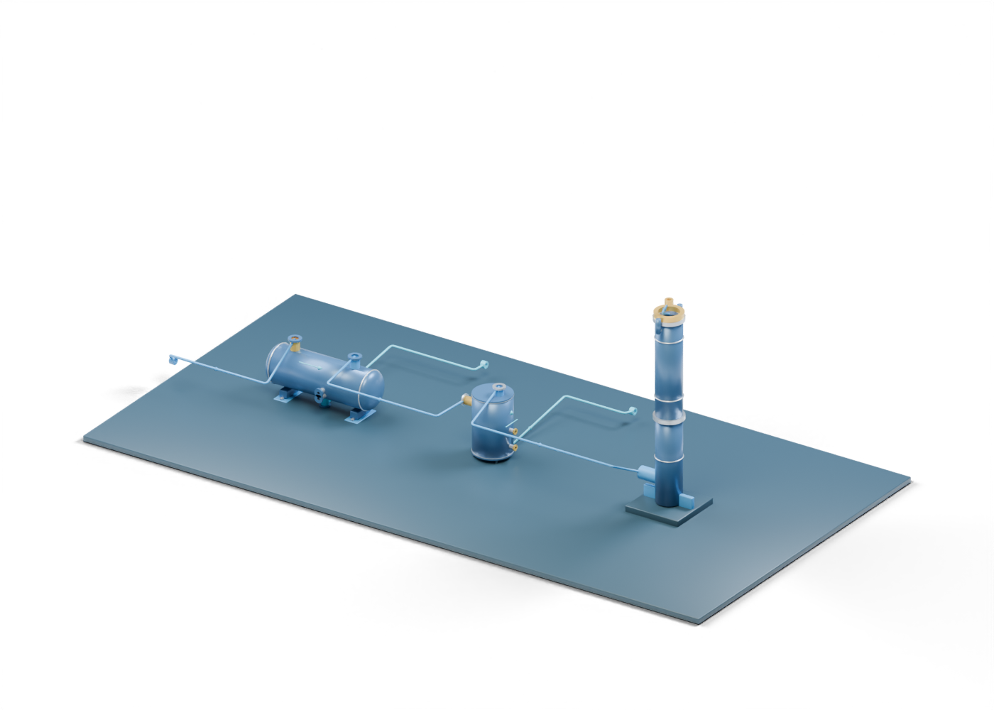
Route / Header reaches liquid knock-out role
Original static relationship; not actual process pipe, relief routing, gas flow or safe operation.
Direction / Header reaches liquid knock-out role
Fixed reading arrow, without measured quantity, pressure, velocity or operating state.
Route / Gas reaches separate liquid-seal role
Original static relationship; not actual process pipe, relief routing, gas flow or safe operation.
Direction / Gas reaches separate liquid-seal role
Fixed reading arrow, without measured quantity, pressure, velocity or operating state.
Route / Knock-out liquid reaches open handling boundary
Original static relationship; not actual process pipe, relief routing, gas flow or safe operation.
Direction / Knock-out liquid reaches open handling boundary
Fixed reading arrow, without measured quantity, pressure, velocity or operating state.
Route / Gas reaches elevated stack inlet
Original static relationship; not actual process pipe, relief routing, gas flow or safe operation.
Direction / Gas reaches elevated stack inlet
Fixed reading arrow, without measured quantity, pressure, velocity or operating state.
Route / Seal-vessel liquid reaches open handling boundary
Original static relationship; not actual process pipe, relief routing, gas flow or safe operation.
Direction / Seal-vessel liquid reaches open handling boundary
Fixed reading arrow, without measured quantity, pressure, velocity or operating state.
Route / Tip location reaches open atmospheric boundary
Original static relationship; not actual process pipe, relief routing, gas flow or safe operation.
Direction / Tip location reaches open atmospheric boundary
Fixed reading arrow, without measured quantity, pressure, velocity or operating state.