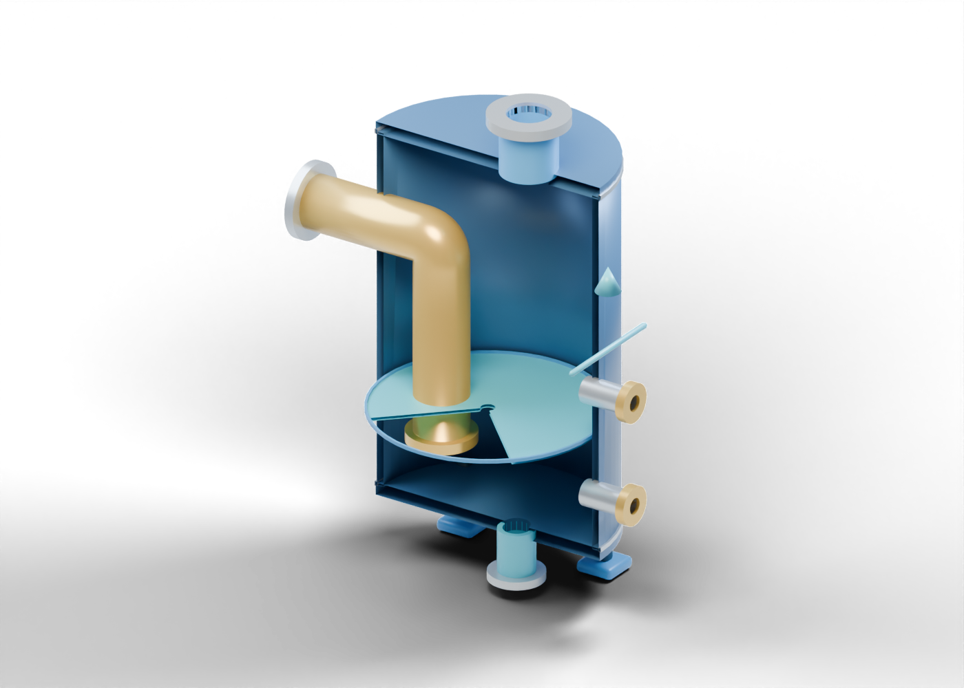
Seal-vessel hollow wall
Vertical open-ended shell with actual side passages. Invented educational geometry only; no selected liquid head, gas duty, pressure rating, flashback protection or operating instruction.
Upper vessel closure
Upper enclosing plate with a real outlet opening. Invented educational geometry only; no selected liquid head, gas duty, pressure rating, flashback protection or operating instruction.
Lower vessel closure
Lower enclosing plate with a real drain opening. Invented educational geometry only; no selected liquid head, gas duty, pressure rating, flashback protection or operating instruction.
Lower shell seam marker
Visible junction marker, not a weld or inspection record. Invented educational geometry only; no selected liquid head, gas duty, pressure rating, flashback protection or operating instruction.
Upper shell seam marker
Visible junction marker, not a weld or inspection record. Invented educational geometry only; no selected liquid head, gas duty, pressure rating, flashback protection or operating instruction.
Bent inlet and submerged leg
One open tube enters from the header side and turns downward below the static blue surface. The illustrated immersion does not establish a functioning seal. Invented educational geometry only; no selected liquid head, gas duty, pressure rating, flashback protection or operating instruction.
Header-side inlet collar
Open connection boundary; upstream knock-out drum and header are outside this model. Invented educational geometry only; no selected liquid head, gas duty, pressure rating, flashback protection or operating instruction.
Submerged leg outlet ring
Separate open end marker inside the liquid region; no bubble, backflow or pressure behaviour is simulated. Invented educational geometry only; no selected liquid head, gas duty, pressure rating, flashback protection or operating instruction.
Illustrative liquid surface
Static reading plane. It is not water inventory, a measured level, calculated liquid head or proof of a protective seal. Invented educational geometry only; no selected liquid head, gas duty, pressure rating, flashback protection or operating instruction.
Liquid surface edge marker
Circular level-reading marker at an arbitrary height. Invented educational geometry only; no selected liquid head, gas duty, pressure rating, flashback protection or operating instruction.
Downstream gas outlet neck
Open upper destination toward downstream flare equipment, which is not modeled. Invented educational geometry only; no selected liquid head, gas duty, pressure rating, flashback protection or operating instruction.
Downstream outlet collar
Unrated open boundary marker; no connected stack, purge or flare tip. Invented educational geometry only; no selected liquid head, gas duty, pressure rating, flashback protection or operating instruction.
Lower liquid drain neck
Open liquid-removal boundary. Storage, treatment and controls are outside the model. Invented educational geometry only; no selected liquid head, gas duty, pressure rating, flashback protection or operating instruction.
Drain outlet collar
Unrated annular drain boundary; no disposal or closed valve is shown. Invented educational geometry only; no selected liquid head, gas duty, pressure rating, flashback protection or operating instruction.
Lower level boundary neck
Open instrument connection location without a gauge, control logic or setpoint. Invented educational geometry only; no selected liquid head, gas duty, pressure rating, flashback protection or operating instruction.
Lower level boundary collar
Separate bored connection marker, without a rated joint. Invented educational geometry only; no selected liquid head, gas duty, pressure rating, flashback protection or operating instruction.
Upper level boundary neck
Open instrument connection location without a gauge, control logic or setpoint. Invented educational geometry only; no selected liquid head, gas duty, pressure rating, flashback protection or operating instruction.
Upper level boundary collar
Separate bored connection marker, without a rated joint. Invented educational geometry only; no selected liquid head, gas duty, pressure rating, flashback protection or operating instruction.
Support leg -0.68 -0.68
Independent support position without structural or foundation design. Invented educational geometry only; no selected liquid head, gas duty, pressure rating, flashback protection or operating instruction.
Support foot -0.68 -0.68
Foot with a geometric anchor opening; no fastener specification. Invented educational geometry only; no selected liquid head, gas duty, pressure rating, flashback protection or operating instruction.
Support leg -0.68 +0.68
Independent support position without structural or foundation design. Invented educational geometry only; no selected liquid head, gas duty, pressure rating, flashback protection or operating instruction.
Support foot -0.68 +0.68
Foot with a geometric anchor opening; no fastener specification. Invented educational geometry only; no selected liquid head, gas duty, pressure rating, flashback protection or operating instruction.
Support leg +0.68 -0.68
Independent support position without structural or foundation design. Invented educational geometry only; no selected liquid head, gas duty, pressure rating, flashback protection or operating instruction.
Support foot +0.68 -0.68
Foot with a geometric anchor opening; no fastener specification. Invented educational geometry only; no selected liquid head, gas duty, pressure rating, flashback protection or operating instruction.
Support leg +0.68 +0.68
Independent support position without structural or foundation design. Invented educational geometry only; no selected liquid head, gas duty, pressure rating, flashback protection or operating instruction.
Support foot +0.68 +0.68
Foot with a geometric anchor opening; no fastener specification. Invented educational geometry only; no selected liquid head, gas duty, pressure rating, flashback protection or operating instruction.
External reading arrow shaft
Static reading direction outside the vessel; not a gas velocity or operating state. Invented educational geometry only; no selected liquid head, gas duty, pressure rating, flashback protection or operating instruction.
External reading arrow head
Static downstream-direction marker outside the vessel. Invented educational geometry only; no selected liquid head, gas duty, pressure rating, flashback protection or operating instruction.