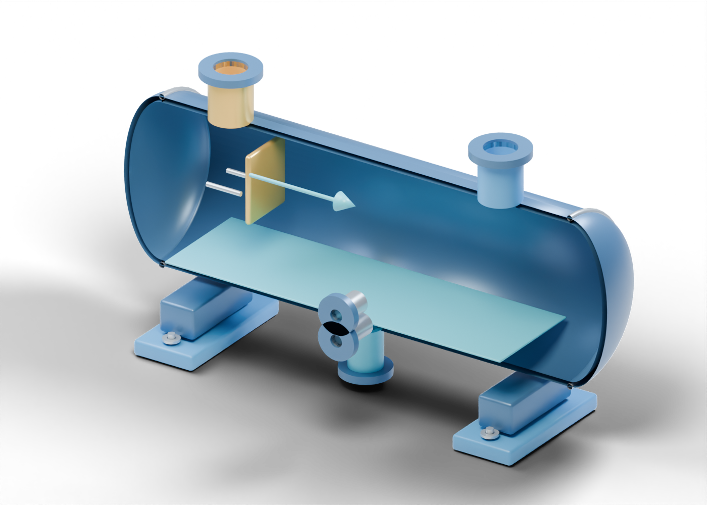
Knock-out drum hollow shell
Separate outer and inner cylindrical surfaces with real wall openings. Original invented teaching geometry; no design, rating, liquid-removal performance, flare safety or service qualification.
Dished closure -1
Generic double-surface dished closure. Shape and thickness are illustrative, with no code qualification.
Head seam marker -1
Illustrative junction location, without weld design. Original invented teaching geometry; no design, rating, liquid-removal performance, flare safety or service qualification.
Dished closure 1
Generic double-surface dished closure. Shape and thickness are illustrative, with no code qualification.
Head seam marker 1
Illustrative junction location, without weld design. Original invented teaching geometry; no design, rating, liquid-removal performance, flare safety or service qualification.
Header inlet hollow neck
Open boundary at the drilled wall. No selected connection, instrument or destination. Original invented teaching geometry; no design, rating, liquid-removal performance, flare safety or service qualification.
Header inlet bored end collar
Separate open collar without a rated face, gasket or matched pipe. Original invented teaching geometry; no design, rating, liquid-removal performance, flare safety or service qualification.
Gas outlet hollow neck
Open boundary at the drilled wall. No selected connection, instrument or destination. Original invented teaching geometry; no design, rating, liquid-removal performance, flare safety or service qualification.
Gas outlet bored end collar
Separate open collar without a rated face, gasket or matched pipe. Original invented teaching geometry; no design, rating, liquid-removal performance, flare safety or service qualification.
Liquid collection outlet hollow neck
Open boundary at the drilled wall. No selected connection, instrument or destination. Original invented teaching geometry; no design, rating, liquid-removal performance, flare safety or service qualification.
Liquid collection outlet bored end collar
Separate open collar without a rated face, gasket or matched pipe. Original invented teaching geometry; no design, rating, liquid-removal performance, flare safety or service qualification.
Lower level boundary hollow neck
Open boundary at the drilled wall. No selected connection, instrument or destination. Original invented teaching geometry; no design, rating, liquid-removal performance, flare safety or service qualification.
Lower level boundary bored end collar
Separate open collar without a rated face, gasket or matched pipe. Original invented teaching geometry; no design, rating, liquid-removal performance, flare safety or service qualification.
Upper level boundary hollow neck
Open boundary at the drilled wall. No selected connection, instrument or destination. Original invented teaching geometry; no design, rating, liquid-removal performance, flare safety or service qualification.
Upper level boundary bored end collar
Separate open collar without a rated face, gasket or matched pipe. Original invented teaching geometry; no design, rating, liquid-removal performance, flare safety or service qualification.
Inlet impact plate
Independent splash/impact location. No selected baffle, strength or droplet-removal performance. Original invented teaching geometry; no design, rating, liquid-removal performance, flare safety or service qualification.
Inlet plate standoff 1
Geometric location marker without weld, load or material specification. Original invented teaching geometry; no design, rating, liquid-removal performance, flare safety or service qualification.
Inlet plate standoff 2
Geometric location marker without weld, load or material specification. Original invented teaching geometry; no design, rating, liquid-removal performance, flare safety or service qualification.
Inlet plate standoff 3
Geometric location marker without weld, load or material specification. Original invented teaching geometry; no design, rating, liquid-removal performance, flare safety or service qualification.
Illustrative liquid-region plane
Static colour boundary only. It is not actual liquid, capacity or a live gauge. Original invented teaching geometry; no design, rating, liquid-removal performance, flare safety or service qualification.
Vessel support saddle -2.03
Separate support location without load or foundation design. Original invented teaching geometry; no design, rating, liquid-removal performance, flare safety or service qualification.
Support foot -2.03
Base location with two true anchor openings. Original invented teaching geometry; no design, rating, liquid-removal performance, flare safety or service qualification.
Support -2.03 anchor 1 smooth rod
Location marker; no embedded anchor or clamp load. Original invented teaching geometry; no design, rating, liquid-removal performance, flare safety or service qualification.
Support -2.03 anchor 1 washer
Independent annular washer location. Original invented teaching geometry; no design, rating, liquid-removal performance, flare safety or service qualification.
Support -2.03 anchor 2 smooth rod
Location marker; no embedded anchor or clamp load. Original invented teaching geometry; no design, rating, liquid-removal performance, flare safety or service qualification.
Support -2.03 anchor 2 washer
Independent annular washer location. Original invented teaching geometry; no design, rating, liquid-removal performance, flare safety or service qualification.
Vessel support saddle 2.03
Separate support location without load or foundation design. Original invented teaching geometry; no design, rating, liquid-removal performance, flare safety or service qualification.
Support foot 2.03
Base location with two true anchor openings. Original invented teaching geometry; no design, rating, liquid-removal performance, flare safety or service qualification.
Support 2.03 anchor 1 smooth rod
Location marker; no embedded anchor or clamp load. Original invented teaching geometry; no design, rating, liquid-removal performance, flare safety or service qualification.
Support 2.03 anchor 1 washer
Independent annular washer location. Original invented teaching geometry; no design, rating, liquid-removal performance, flare safety or service qualification.
Support 2.03 anchor 2 smooth rod
Location marker; no embedded anchor or clamp load. Original invented teaching geometry; no design, rating, liquid-removal performance, flare safety or service qualification.
Support 2.03 anchor 2 washer
Independent annular washer location. Original invented teaching geometry; no design, rating, liquid-removal performance, flare safety or service qualification.
External gas-path arrow shaft
Reading direction only; no actual velocity, combustion or gas flow. Original invented teaching geometry; no design, rating, liquid-removal performance, flare safety or service qualification.
External gas-path arrow head
Static reading arrow outside the vessel. Original invented teaching geometry; no design, rating, liquid-removal performance, flare safety or service qualification.