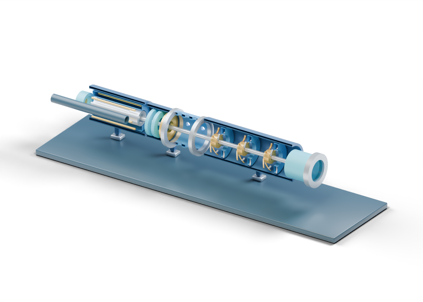
ESP presentation plinth
Reading support, not a foundation or completion. Invented static geometry; no selected well, dimensions, material, voltage, insulation, cooling, seal, bearing load, fluid, gas handling, head, flow, efficiency, speed, pressure, temperature, capacity, run life or safe service.
Complete motor housing wall
Open-ended downhole motor-location enclosure. The poster alone removes the facing half. Invented static geometry; no selected well, dimensions, material, voltage, insulation, cooling, seal, bearing load, fluid, gas handling, head, flow, efficiency, speed, pressure, temperature, capacity, run life or safe service.
Motor stator envelope
Annular stationary motor-region cue, not a winding design. Invented static geometry; no selected well, dimensions, material, voltage, insulation, cooling, seal, bearing load, fluid, gas handling, head, flow, efficiency, speed, pressure, temperature, capacity, run life or safe service.
Motor rotor envelope
Static motor rotor-location solid, not an electromagnetic design. Invented static geometry; no selected well, dimensions, material, voltage, insulation, cooling, seal, bearing load, fluid, gas handling, head, flow, efficiency, speed, pressure, temperature, capacity, run life or safe service.
Motor winding-region cue 1
One of six visible invented conductor-location cues; no winding, insulation or energized circuit is represented. Invented static geometry; no selected well, dimensions, material, voltage, insulation, cooling, seal, bearing load, fluid, gas handling, head, flow, efficiency, speed, pressure, temperature, capacity, run life or safe service.
Motor winding-region cue 2
One of six visible invented conductor-location cues; no winding, insulation or energized circuit is represented. Invented static geometry; no selected well, dimensions, material, voltage, insulation, cooling, seal, bearing load, fluid, gas handling, head, flow, efficiency, speed, pressure, temperature, capacity, run life or safe service.
Motor winding-region cue 3
One of six visible invented conductor-location cues; no winding, insulation or energized circuit is represented. Invented static geometry; no selected well, dimensions, material, voltage, insulation, cooling, seal, bearing load, fluid, gas handling, head, flow, efficiency, speed, pressure, temperature, capacity, run life or safe service.
Motor winding-region cue 4
One of six visible invented conductor-location cues; no winding, insulation or energized circuit is represented. Invented static geometry; no selected well, dimensions, material, voltage, insulation, cooling, seal, bearing load, fluid, gas handling, head, flow, efficiency, speed, pressure, temperature, capacity, run life or safe service.
Motor winding-region cue 5
One of six visible invented conductor-location cues; no winding, insulation or energized circuit is represented. Invented static geometry; no selected well, dimensions, material, voltage, insulation, cooling, seal, bearing load, fluid, gas handling, head, flow, efficiency, speed, pressure, temperature, capacity, run life or safe service.
Motor winding-region cue 6
One of six visible invented conductor-location cues; no winding, insulation or energized circuit is represented. Invented static geometry; no selected well, dimensions, material, voltage, insulation, cooling, seal, bearing load, fluid, gas handling, head, flow, efficiency, speed, pressure, temperature, capacity, run life or safe service.
Motor lower sensor-location sleeve
Open sensor-location envelope; no instrument is fitted or measured. Invented static geometry; no selected well, dimensions, material, voltage, insulation, cooling, seal, bearing load, fluid, gas handling, head, flow, efficiency, speed, pressure, temperature, capacity, run life or safe service.
Static sensor core marker
Separate uninstrumented core marker. Invented static geometry; no selected well, dimensions, material, voltage, insulation, cooling, seal, bearing load, fluid, gas handling, head, flow, efficiency, speed, pressure, temperature, capacity, run life or safe service.
Complete protector housing wall
Open-ended protector/seal-section location; no actual fluid barrier or pressure equalization is modeled. The poster alone sections its facing half. Invented static geometry; no selected well, dimensions, material, voltage, insulation, cooling, seal, bearing load, fluid, gas handling, head, flow, efficiency, speed, pressure, temperature, capacity, run life or safe service.
Protector static barrier-location ring 1
Separate annular internal location cue; no selected bag, labyrinth, seal or fluid isolation. Invented static geometry; no selected well, dimensions, material, voltage, insulation, cooling, seal, bearing load, fluid, gas handling, head, flow, efficiency, speed, pressure, temperature, capacity, run life or safe service.
Protector static barrier-location ring 2
Separate annular internal location cue; no selected bag, labyrinth, seal or fluid isolation. Invented static geometry; no selected well, dimensions, material, voltage, insulation, cooling, seal, bearing load, fluid, gas handling, head, flow, efficiency, speed, pressure, temperature, capacity, run life or safe service.
Protector thrust-bearing location
Annular thrust-bearing location only; no rolling elements, load capacity or supported thrust result. Invented static geometry; no selected well, dimensions, material, voltage, insulation, cooling, seal, bearing load, fluid, gas handling, head, flow, efficiency, speed, pressure, temperature, capacity, run life or safe service.
Complete bored pump-intake wall
Separate open intake region with twelve real side openings. The pattern is invented and does not separate gas or screen solids. Invented static geometry; no selected well, dimensions, material, voltage, insulation, cooling, seal, bearing load, fluid, gas handling, head, flow, efficiency, speed, pressure, temperature, capacity, run life or safe service.
Intake lower open collar
Open collar distinguishing the lower intake boundary. Invented static geometry; no selected well, dimensions, material, voltage, insulation, cooling, seal, bearing load, fluid, gas handling, head, flow, efficiency, speed, pressure, temperature, capacity, run life or safe service.
Intake upper open collar
Open collar distinguishing the pump-side boundary. Invented static geometry; no selected well, dimensions, material, voltage, insulation, cooling, seal, bearing load, fluid, gas handling, head, flow, efficiency, speed, pressure, temperature, capacity, run life or safe service.
Complete multistage pump housing wall
Open-ended multistage pump enclosure. Three invented visible stages are used for teaching, not a selected stage count. The poster alone removes its facing half. Invented static geometry; no selected well, dimensions, material, voltage, insulation, cooling, seal, bearing load, fluid, gas handling, head, flow, efficiency, speed, pressure, temperature, capacity, run life or safe service.
Stage 1 impeller hub
Static annular impeller centre for stage reading; not a selected hydraulic design. Invented static geometry; no selected well, dimensions, material, voltage, insulation, cooling, seal, bearing load, fluid, gas handling, head, flow, efficiency, speed, pressure, temperature, capacity, run life or safe service.
Stage 1 impeller vane 1
Original curved visual fin for the rotating-stage region. It is static and has no head/flow result. Invented static geometry; no selected well, dimensions, material, voltage, insulation, cooling, seal, bearing load, fluid, gas handling, head, flow, efficiency, speed, pressure, temperature, capacity, run life or safe service.
Stage 1 impeller vane 2
Original curved visual fin for the rotating-stage region. It is static and has no head/flow result. Invented static geometry; no selected well, dimensions, material, voltage, insulation, cooling, seal, bearing load, fluid, gas handling, head, flow, efficiency, speed, pressure, temperature, capacity, run life or safe service.
Stage 1 impeller vane 3
Original curved visual fin for the rotating-stage region. It is static and has no head/flow result. Invented static geometry; no selected well, dimensions, material, voltage, insulation, cooling, seal, bearing load, fluid, gas handling, head, flow, efficiency, speed, pressure, temperature, capacity, run life or safe service.
Stage 1 impeller vane 4
Original curved visual fin for the rotating-stage region. It is static and has no head/flow result. Invented static geometry; no selected well, dimensions, material, voltage, insulation, cooling, seal, bearing load, fluid, gas handling, head, flow, efficiency, speed, pressure, temperature, capacity, run life or safe service.
Stage 1 impeller vane 5
Original curved visual fin for the rotating-stage region. It is static and has no head/flow result. Invented static geometry; no selected well, dimensions, material, voltage, insulation, cooling, seal, bearing load, fluid, gas handling, head, flow, efficiency, speed, pressure, temperature, capacity, run life or safe service.
Stage 1 impeller vane 6
Original curved visual fin for the rotating-stage region. It is static and has no head/flow result. Invented static geometry; no selected well, dimensions, material, voltage, insulation, cooling, seal, bearing load, fluid, gas handling, head, flow, efficiency, speed, pressure, temperature, capacity, run life or safe service.
Stage 1 diffuser carrier
Stationary annular diffuser-region support. Invented passage geometry. Invented static geometry; no selected well, dimensions, material, voltage, insulation, cooling, seal, bearing load, fluid, gas handling, head, flow, efficiency, speed, pressure, temperature, capacity, run life or safe service.
Stage 1 diffuser vane 1
Separate static diffuser-region fin; no recovered pressure or hydraulic curve is implied. Invented static geometry; no selected well, dimensions, material, voltage, insulation, cooling, seal, bearing load, fluid, gas handling, head, flow, efficiency, speed, pressure, temperature, capacity, run life or safe service.
Stage 1 diffuser vane 2
Separate static diffuser-region fin; no recovered pressure or hydraulic curve is implied. Invented static geometry; no selected well, dimensions, material, voltage, insulation, cooling, seal, bearing load, fluid, gas handling, head, flow, efficiency, speed, pressure, temperature, capacity, run life or safe service.
Stage 1 diffuser vane 3
Separate static diffuser-region fin; no recovered pressure or hydraulic curve is implied. Invented static geometry; no selected well, dimensions, material, voltage, insulation, cooling, seal, bearing load, fluid, gas handling, head, flow, efficiency, speed, pressure, temperature, capacity, run life or safe service.
Stage 1 diffuser vane 4
Separate static diffuser-region fin; no recovered pressure or hydraulic curve is implied. Invented static geometry; no selected well, dimensions, material, voltage, insulation, cooling, seal, bearing load, fluid, gas handling, head, flow, efficiency, speed, pressure, temperature, capacity, run life or safe service.
Stage 1 diffuser vane 5
Separate static diffuser-region fin; no recovered pressure or hydraulic curve is implied. Invented static geometry; no selected well, dimensions, material, voltage, insulation, cooling, seal, bearing load, fluid, gas handling, head, flow, efficiency, speed, pressure, temperature, capacity, run life or safe service.
Stage 2 impeller hub
Static annular impeller centre for stage reading; not a selected hydraulic design. Invented static geometry; no selected well, dimensions, material, voltage, insulation, cooling, seal, bearing load, fluid, gas handling, head, flow, efficiency, speed, pressure, temperature, capacity, run life or safe service.
Stage 2 impeller vane 1
Original curved visual fin for the rotating-stage region. It is static and has no head/flow result. Invented static geometry; no selected well, dimensions, material, voltage, insulation, cooling, seal, bearing load, fluid, gas handling, head, flow, efficiency, speed, pressure, temperature, capacity, run life or safe service.
Stage 2 impeller vane 2
Original curved visual fin for the rotating-stage region. It is static and has no head/flow result. Invented static geometry; no selected well, dimensions, material, voltage, insulation, cooling, seal, bearing load, fluid, gas handling, head, flow, efficiency, speed, pressure, temperature, capacity, run life or safe service.
Stage 2 impeller vane 3
Original curved visual fin for the rotating-stage region. It is static and has no head/flow result. Invented static geometry; no selected well, dimensions, material, voltage, insulation, cooling, seal, bearing load, fluid, gas handling, head, flow, efficiency, speed, pressure, temperature, capacity, run life or safe service.
Stage 2 impeller vane 4
Original curved visual fin for the rotating-stage region. It is static and has no head/flow result. Invented static geometry; no selected well, dimensions, material, voltage, insulation, cooling, seal, bearing load, fluid, gas handling, head, flow, efficiency, speed, pressure, temperature, capacity, run life or safe service.
Stage 2 impeller vane 5
Original curved visual fin for the rotating-stage region. It is static and has no head/flow result. Invented static geometry; no selected well, dimensions, material, voltage, insulation, cooling, seal, bearing load, fluid, gas handling, head, flow, efficiency, speed, pressure, temperature, capacity, run life or safe service.
Stage 2 impeller vane 6
Original curved visual fin for the rotating-stage region. It is static and has no head/flow result. Invented static geometry; no selected well, dimensions, material, voltage, insulation, cooling, seal, bearing load, fluid, gas handling, head, flow, efficiency, speed, pressure, temperature, capacity, run life or safe service.
Stage 2 diffuser carrier
Stationary annular diffuser-region support. Invented passage geometry. Invented static geometry; no selected well, dimensions, material, voltage, insulation, cooling, seal, bearing load, fluid, gas handling, head, flow, efficiency, speed, pressure, temperature, capacity, run life or safe service.
Stage 2 diffuser vane 1
Separate static diffuser-region fin; no recovered pressure or hydraulic curve is implied. Invented static geometry; no selected well, dimensions, material, voltage, insulation, cooling, seal, bearing load, fluid, gas handling, head, flow, efficiency, speed, pressure, temperature, capacity, run life or safe service.
Stage 2 diffuser vane 2
Separate static diffuser-region fin; no recovered pressure or hydraulic curve is implied. Invented static geometry; no selected well, dimensions, material, voltage, insulation, cooling, seal, bearing load, fluid, gas handling, head, flow, efficiency, speed, pressure, temperature, capacity, run life or safe service.
Stage 2 diffuser vane 3
Separate static diffuser-region fin; no recovered pressure or hydraulic curve is implied. Invented static geometry; no selected well, dimensions, material, voltage, insulation, cooling, seal, bearing load, fluid, gas handling, head, flow, efficiency, speed, pressure, temperature, capacity, run life or safe service.
Stage 2 diffuser vane 4
Separate static diffuser-region fin; no recovered pressure or hydraulic curve is implied. Invented static geometry; no selected well, dimensions, material, voltage, insulation, cooling, seal, bearing load, fluid, gas handling, head, flow, efficiency, speed, pressure, temperature, capacity, run life or safe service.
Stage 2 diffuser vane 5
Separate static diffuser-region fin; no recovered pressure or hydraulic curve is implied. Invented static geometry; no selected well, dimensions, material, voltage, insulation, cooling, seal, bearing load, fluid, gas handling, head, flow, efficiency, speed, pressure, temperature, capacity, run life or safe service.
Stage 3 impeller hub
Static annular impeller centre for stage reading; not a selected hydraulic design. Invented static geometry; no selected well, dimensions, material, voltage, insulation, cooling, seal, bearing load, fluid, gas handling, head, flow, efficiency, speed, pressure, temperature, capacity, run life or safe service.
Stage 3 impeller vane 1
Original curved visual fin for the rotating-stage region. It is static and has no head/flow result. Invented static geometry; no selected well, dimensions, material, voltage, insulation, cooling, seal, bearing load, fluid, gas handling, head, flow, efficiency, speed, pressure, temperature, capacity, run life or safe service.
Stage 3 impeller vane 2
Original curved visual fin for the rotating-stage region. It is static and has no head/flow result. Invented static geometry; no selected well, dimensions, material, voltage, insulation, cooling, seal, bearing load, fluid, gas handling, head, flow, efficiency, speed, pressure, temperature, capacity, run life or safe service.
Stage 3 impeller vane 3
Original curved visual fin for the rotating-stage region. It is static and has no head/flow result. Invented static geometry; no selected well, dimensions, material, voltage, insulation, cooling, seal, bearing load, fluid, gas handling, head, flow, efficiency, speed, pressure, temperature, capacity, run life or safe service.
Stage 3 impeller vane 4
Original curved visual fin for the rotating-stage region. It is static and has no head/flow result. Invented static geometry; no selected well, dimensions, material, voltage, insulation, cooling, seal, bearing load, fluid, gas handling, head, flow, efficiency, speed, pressure, temperature, capacity, run life or safe service.
Stage 3 impeller vane 5
Original curved visual fin for the rotating-stage region. It is static and has no head/flow result. Invented static geometry; no selected well, dimensions, material, voltage, insulation, cooling, seal, bearing load, fluid, gas handling, head, flow, efficiency, speed, pressure, temperature, capacity, run life or safe service.
Stage 3 impeller vane 6
Original curved visual fin for the rotating-stage region. It is static and has no head/flow result. Invented static geometry; no selected well, dimensions, material, voltage, insulation, cooling, seal, bearing load, fluid, gas handling, head, flow, efficiency, speed, pressure, temperature, capacity, run life or safe service.
Stage 3 diffuser carrier
Stationary annular diffuser-region support. Invented passage geometry. Invented static geometry; no selected well, dimensions, material, voltage, insulation, cooling, seal, bearing load, fluid, gas handling, head, flow, efficiency, speed, pressure, temperature, capacity, run life or safe service.
Stage 3 diffuser vane 1
Separate static diffuser-region fin; no recovered pressure or hydraulic curve is implied. Invented static geometry; no selected well, dimensions, material, voltage, insulation, cooling, seal, bearing load, fluid, gas handling, head, flow, efficiency, speed, pressure, temperature, capacity, run life or safe service.
Stage 3 diffuser vane 2
Separate static diffuser-region fin; no recovered pressure or hydraulic curve is implied. Invented static geometry; no selected well, dimensions, material, voltage, insulation, cooling, seal, bearing load, fluid, gas handling, head, flow, efficiency, speed, pressure, temperature, capacity, run life or safe service.
Stage 3 diffuser vane 3
Separate static diffuser-region fin; no recovered pressure or hydraulic curve is implied. Invented static geometry; no selected well, dimensions, material, voltage, insulation, cooling, seal, bearing load, fluid, gas handling, head, flow, efficiency, speed, pressure, temperature, capacity, run life or safe service.
Stage 3 diffuser vane 4
Separate static diffuser-region fin; no recovered pressure or hydraulic curve is implied. Invented static geometry; no selected well, dimensions, material, voltage, insulation, cooling, seal, bearing load, fluid, gas handling, head, flow, efficiency, speed, pressure, temperature, capacity, run life or safe service.
Stage 3 diffuser vane 5
Separate static diffuser-region fin; no recovered pressure or hydraulic curve is implied. Invented static geometry; no selected well, dimensions, material, voltage, insulation, cooling, seal, bearing load, fluid, gas handling, head, flow, efficiency, speed, pressure, temperature, capacity, run life or safe service.
Static common shaft-axis cue
Continuous visual axis across the teaching sections; it does not rotate or depict actual coupled shaft joints. Invented static geometry; no selected well, dimensions, material, voltage, insulation, cooling, seal, bearing load, fluid, gas handling, head, flow, efficiency, speed, pressure, temperature, capacity, run life or safe service.
Open produced-fluid discharge sleeve
Open conceptual produced-fluid boundary; no tubing connection or measured discharge. Invented static geometry; no selected well, dimensions, material, voltage, insulation, cooling, seal, bearing load, fluid, gas handling, head, flow, efficiency, speed, pressure, temperature, capacity, run life or safe service.
Discharge open end collar
Unrated open upper boundary. Invented static geometry; no selected well, dimensions, material, voltage, insulation, cooling, seal, bearing load, fluid, gas handling, head, flow, efficiency, speed, pressure, temperature, capacity, run life or safe service.
Open external power-cable jacket cue
Open cable-route envelope, not an installed lead, insulation specification or energized circuit. Invented static geometry; no selected well, dimensions, material, voltage, insulation, cooling, seal, bearing load, fluid, gas handling, head, flow, efficiency, speed, pressure, temperature, capacity, run life or safe service.
Power-cable conductor-location cue 1
Isolated visible core-location cue; no voltage, insulation or termination design. Invented static geometry; no selected well, dimensions, material, voltage, insulation, cooling, seal, bearing load, fluid, gas handling, head, flow, efficiency, speed, pressure, temperature, capacity, run life or safe service.
Power-cable conductor-location cue 2
Isolated visible core-location cue; no voltage, insulation or termination design. Invented static geometry; no selected well, dimensions, material, voltage, insulation, cooling, seal, bearing load, fluid, gas handling, head, flow, efficiency, speed, pressure, temperature, capacity, run life or safe service.
Power-cable conductor-location cue 3
Isolated visible core-location cue; no voltage, insulation or termination design. Invented static geometry; no selected well, dimensions, material, voltage, insulation, cooling, seal, bearing load, fluid, gas handling, head, flow, efficiency, speed, pressure, temperature, capacity, run life or safe service.
Motor lead-entry location envelope
Separate location cue beside motor; no electrical seal or pothead connection is represented. Invented static geometry; no selected well, dimensions, material, voltage, insulation, cooling, seal, bearing load, fluid, gas handling, head, flow, efficiency, speed, pressure, temperature, capacity, run life or safe service.
ESP display stand 1
Display support, not downhole hardware. Invented static geometry; no selected well, dimensions, material, voltage, insulation, cooling, seal, bearing load, fluid, gas handling, head, flow, efficiency, speed, pressure, temperature, capacity, run life or safe service.
ESP bored presentation foot 1
Bored display foot, not a structural or installation part. Invented static geometry; no selected well, dimensions, material, voltage, insulation, cooling, seal, bearing load, fluid, gas handling, head, flow, efficiency, speed, pressure, temperature, capacity, run life or safe service.
ESP display stand 2
Display support, not downhole hardware. Invented static geometry; no selected well, dimensions, material, voltage, insulation, cooling, seal, bearing load, fluid, gas handling, head, flow, efficiency, speed, pressure, temperature, capacity, run life or safe service.
ESP bored presentation foot 2
Bored display foot, not a structural or installation part. Invented static geometry; no selected well, dimensions, material, voltage, insulation, cooling, seal, bearing load, fluid, gas handling, head, flow, efficiency, speed, pressure, temperature, capacity, run life or safe service.
ESP display stand 3
Display support, not downhole hardware. Invented static geometry; no selected well, dimensions, material, voltage, insulation, cooling, seal, bearing load, fluid, gas handling, head, flow, efficiency, speed, pressure, temperature, capacity, run life or safe service.
ESP bored presentation foot 3
Bored display foot, not a structural or installation part. Invented static geometry; no selected well, dimensions, material, voltage, insulation, cooling, seal, bearing load, fluid, gas handling, head, flow, efficiency, speed, pressure, temperature, capacity, run life or safe service.
ESP display stand 4
Display support, not downhole hardware. Invented static geometry; no selected well, dimensions, material, voltage, insulation, cooling, seal, bearing load, fluid, gas handling, head, flow, efficiency, speed, pressure, temperature, capacity, run life or safe service.
ESP bored presentation foot 4
Bored display foot, not a structural or installation part. Invented static geometry; no selected well, dimensions, material, voltage, insulation, cooling, seal, bearing load, fluid, gas handling, head, flow, efficiency, speed, pressure, temperature, capacity, run life or safe service.
ESP display stand 5
Display support, not downhole hardware. Invented static geometry; no selected well, dimensions, material, voltage, insulation, cooling, seal, bearing load, fluid, gas handling, head, flow, efficiency, speed, pressure, temperature, capacity, run life or safe service.
ESP bored presentation foot 5
Bored display foot, not a structural or installation part. Invented static geometry; no selected well, dimensions, material, voltage, insulation, cooling, seal, bearing load, fluid, gas handling, head, flow, efficiency, speed, pressure, temperature, capacity, run life or safe service.
ESP display stand 6
Display support, not downhole hardware. Invented static geometry; no selected well, dimensions, material, voltage, insulation, cooling, seal, bearing load, fluid, gas handling, head, flow, efficiency, speed, pressure, temperature, capacity, run life or safe service.
ESP bored presentation foot 6
Bored display foot, not a structural or installation part. Invented static geometry; no selected well, dimensions, material, voltage, insulation, cooling, seal, bearing load, fluid, gas handling, head, flow, efficiency, speed, pressure, temperature, capacity, run life or safe service.