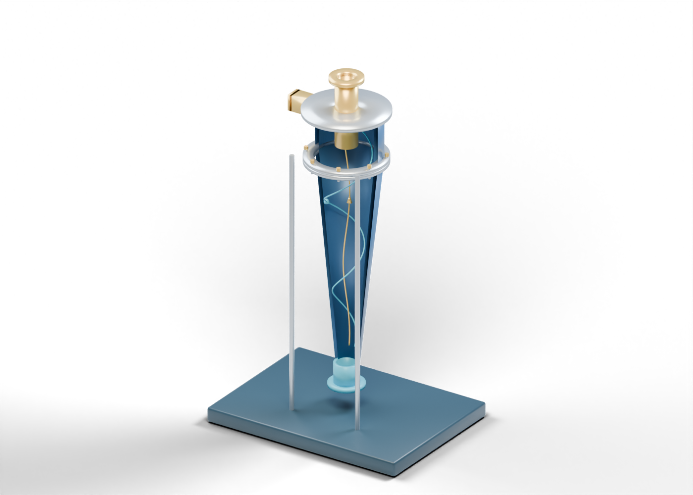
Base frame
Illustrative support frame; foundations and structural design vary.
Complete hollow inlet head
Upper liner/head envelope with an actual offset side opening. Original static teaching geometry; no vendor liner, hydraulic design, pressure rating, separation efficiency, effluent quality or service procedure.
Complete long tapered liner
Continuous hollow taper with inner and outer surfaces, open at both ends. Original static teaching geometry; no vendor liner, hydraulic design, pressure rating, separation efficiency, effluent quality or service procedure.
Open offset produced-water feed
Open feed duct meeting the head near its wall; orientation is a role cue, not a selected inlet. Original static teaching geometry; no vendor liner, hydraulic design, pressure rating, separation efficiency, effluent quality or service procedure.
Open feed flange
Separate open rectangular interface; no selected joint or rated flange. Original static teaching geometry; no vendor liner, hydraulic design, pressure rating, separation efficiency, effluent quality or service procedure.
Head top annular closure
Closed annular top outside the central reject passage. Original static teaching geometry; no vendor liner, hydraulic design, pressure rating, separation efficiency, effluent quality or service procedure.
Central oil-reject finder
Hollow central extension into the inlet head and out of the top. Original static teaching geometry; no vendor liner, hydraulic design, pressure rating, separation efficiency, effluent quality or service procedure.
Open oil-reject flange
Open upper reject boundary; it does not specify recycling or oil recovery. Original static teaching geometry; no vendor liner, hydraulic design, pressure rating, separation efficiency, effluent quality or service procedure.
Lower treated-water outlet
Open lower water-rich boundary; additional treatment or approved handling remains outside the model. Original static teaching geometry; no vendor liner, hydraulic design, pressure rating, separation efficiency, effluent quality or service procedure.
Open water-outlet flange
Separate open lower flange; no discharge, reuse or injection permission. Original static teaching geometry; no vendor liner, hydraulic design, pressure rating, separation efficiency, effluent quality or service procedure.
Head joint upper ring
Separate conceptual head/liner interface, without seal or fastening qualification. Original static teaching geometry; no vendor liner, hydraulic design, pressure rating, separation efficiency, effluent quality or service procedure.
Head joint lower ring
Separate conceptual head/liner interface, without seal or fastening qualification. Original static teaching geometry; no vendor liner, hydraulic design, pressure rating, separation efficiency, effluent quality or service procedure.
Head joint gasket marker
Separate conceptual head/liner interface, without seal or fastening qualification. Original static teaching geometry; no vendor liner, hydraulic design, pressure rating, separation efficiency, effluent quality or service procedure.
Head joint smooth stud 1
Separate fastener location; no thread, tension or pressure joint. Original static teaching geometry; no vendor liner, hydraulic design, pressure rating, separation efficiency, effluent quality or service procedure.
Head joint nut marker 1
External nut shape only; fit and preload are not verified. Original static teaching geometry; no vendor liner, hydraulic design, pressure rating, separation efficiency, effluent quality or service procedure.
Head joint smooth stud 2
Separate fastener location; no thread, tension or pressure joint. Original static teaching geometry; no vendor liner, hydraulic design, pressure rating, separation efficiency, effluent quality or service procedure.
Head joint nut marker 2
External nut shape only; fit and preload are not verified. Original static teaching geometry; no vendor liner, hydraulic design, pressure rating, separation efficiency, effluent quality or service procedure.
Head joint smooth stud 3
Separate fastener location; no thread, tension or pressure joint. Original static teaching geometry; no vendor liner, hydraulic design, pressure rating, separation efficiency, effluent quality or service procedure.
Head joint nut marker 3
External nut shape only; fit and preload are not verified. Original static teaching geometry; no vendor liner, hydraulic design, pressure rating, separation efficiency, effluent quality or service procedure.
Head joint smooth stud 4
Separate fastener location; no thread, tension or pressure joint. Original static teaching geometry; no vendor liner, hydraulic design, pressure rating, separation efficiency, effluent quality or service procedure.
Head joint nut marker 4
External nut shape only; fit and preload are not verified. Original static teaching geometry; no vendor liner, hydraulic design, pressure rating, separation efficiency, effluent quality or service procedure.
Head joint smooth stud 5
Separate fastener location; no thread, tension or pressure joint. Original static teaching geometry; no vendor liner, hydraulic design, pressure rating, separation efficiency, effluent quality or service procedure.
Head joint nut marker 5
External nut shape only; fit and preload are not verified. Original static teaching geometry; no vendor liner, hydraulic design, pressure rating, separation efficiency, effluent quality or service procedure.
Head joint smooth stud 6
Separate fastener location; no thread, tension or pressure joint. Original static teaching geometry; no vendor liner, hydraulic design, pressure rating, separation efficiency, effluent quality or service procedure.
Head joint nut marker 6
External nut shape only; fit and preload are not verified. Original static teaching geometry; no vendor liner, hydraulic design, pressure rating, separation efficiency, effluent quality or service procedure.
Head joint smooth stud 7
Separate fastener location; no thread, tension or pressure joint. Original static teaching geometry; no vendor liner, hydraulic design, pressure rating, separation efficiency, effluent quality or service procedure.
Head joint nut marker 7
External nut shape only; fit and preload are not verified. Original static teaching geometry; no vendor liner, hydraulic design, pressure rating, separation efficiency, effluent quality or service procedure.
Head joint smooth stud 8
Separate fastener location; no thread, tension or pressure joint. Original static teaching geometry; no vendor liner, hydraulic design, pressure rating, separation efficiency, effluent quality or service procedure.
Head joint nut marker 8
External nut shape only; fit and preload are not verified. Original static teaching geometry; no vendor liner, hydraulic design, pressure rating, separation efficiency, effluent quality or service procedure.
Presentation support 1
Display frame location, without structural or foundation design. Original static teaching geometry; no vendor liner, hydraulic design, pressure rating, separation efficiency, effluent quality or service procedure.
Presentation foot 1
Unrated display foot without anchors or loads. Original static teaching geometry; no vendor liner, hydraulic design, pressure rating, separation efficiency, effluent quality or service procedure.
Presentation support 2
Display frame location, without structural or foundation design. Original static teaching geometry; no vendor liner, hydraulic design, pressure rating, separation efficiency, effluent quality or service procedure.
Presentation foot 2
Unrated display foot without anchors or loads. Original static teaching geometry; no vendor liner, hydraulic design, pressure rating, separation efficiency, effluent quality or service procedure.
Presentation support 3
Display frame location, without structural or foundation design. Original static teaching geometry; no vendor liner, hydraulic design, pressure rating, separation efficiency, effluent quality or service procedure.
Presentation foot 3
Unrated display foot without anchors or loads. Original static teaching geometry; no vendor liner, hydraulic design, pressure rating, separation efficiency, effluent quality or service procedure.
Presentation support 4
Display frame location, without structural or foundation design. Original static teaching geometry; no vendor liner, hydraulic design, pressure rating, separation efficiency, effluent quality or service procedure.
Presentation foot 4
Unrated display foot without anchors or loads. Original static teaching geometry; no vendor liner, hydraulic design, pressure rating, separation efficiency, effluent quality or service procedure.
Static outer water-rich path cue
Fixed visual line for a possible outer water-rich direction, not actual fluid motion. Original static teaching geometry; no vendor liner, hydraulic design, pressure rating, separation efficiency, effluent quality or service procedure.
Static central oil-rich path cue
Fixed visual line for the contrasting central reject direction, not actual fluid motion. Original static teaching geometry; no vendor liner, hydraulic design, pressure rating, separation efficiency, effluent quality or service procedure.
Outer direction arrow
Fixed visual direction cue, not flow, velocity or separation performance. Original static teaching geometry; no vendor liner, hydraulic design, pressure rating, separation efficiency, effluent quality or service procedure.
Central direction arrow
Fixed visual direction cue, not flow, velocity or separation performance. Original static teaching geometry; no vendor liner, hydraulic design, pressure rating, separation efficiency, effluent quality or service procedure.