Scrubber presentation plinth
Display base, not an installed foundation. Generic static teaching geometry; no selected fluid, capture efficiency, pressure rating, level logic, compressor interlock, drain action, material, access or structural design is shown.
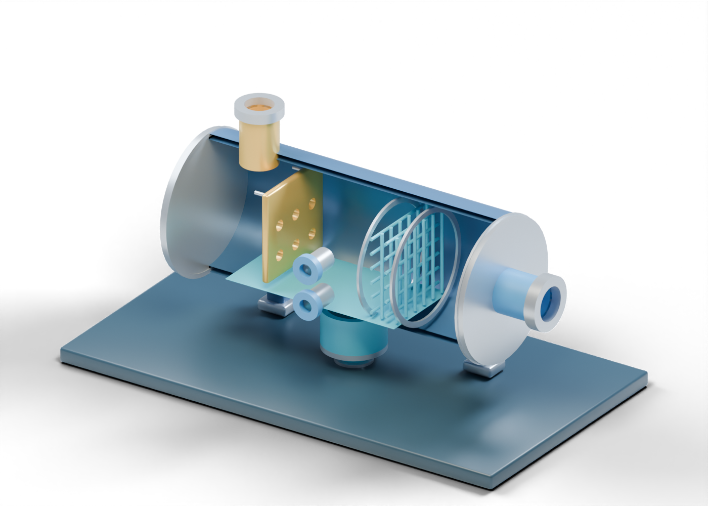
Complete hollow scrubber shell
Complete double-surface horizontal enclosure with five separate wall openings. Generic static teaching geometry; no selected fluid, capture efficiency, pressure rating, level logic, compressor interlock, drain action, material, access or structural design is shown.
Closed inlet-side vessel cap
Closed static end, without a selected vessel-head profile. Generic static teaching geometry; no selected fluid, capture efficiency, pressure rating, level logic, compressor interlock, drain action, material, access or structural design is shown.
Bored outlet-side vessel cap
End closure with one actual gas-outlet passage. Generic static teaching geometry; no selected fluid, capture efficiency, pressure rating, level logic, compressor interlock, drain action, material, access or structural design is shown.
Inlet-side seam marker
Visible boundary, not a specified weld. Generic static teaching geometry; no selected fluid, capture efficiency, pressure rating, level logic, compressor interlock, drain action, material, access or structural design is shown.
Outlet-side seam marker
Visible boundary, not a specified weld. Generic static teaching geometry; no selected fluid, capture efficiency, pressure rating, level logic, compressor interlock, drain action, material, access or structural design is shown.
Mixed-gas inlet hollow neck
Open feed boundary at an actual shell passage. Generic static teaching geometry; no selected fluid, capture efficiency, pressure rating, level logic, compressor interlock, drain action, material, access or structural design is shown.
Mixed-gas inlet open collar
Separate open connection marker; mating pipe omitted. Generic static teaching geometry; no selected fluid, capture efficiency, pressure rating, level logic, compressor interlock, drain action, material, access or structural design is shown.
Compressor-side gas outlet hollow neck
Open gas boundary beyond the bored end closure; no connected compressor is depicted. Generic static teaching geometry; no selected fluid, capture efficiency, pressure rating, level logic, compressor interlock, drain action, material, access or structural design is shown.
Compressor-side gas outlet open collar
Separate open outlet marker, without a rated joint. Generic static teaching geometry; no selected fluid, capture efficiency, pressure rating, level logic, compressor interlock, drain action, material, access or structural design is shown.
Perforated inlet diversion plate
Possible initial diversion location with six actual holes; no bulk-liquid-removal result. Generic static teaching geometry; no selected fluid, capture efficiency, pressure rating, level logic, compressor interlock, drain action, material, access or structural design is shown.
Inlet plate stand-off -0.42
Illustrative location tie, not structural design. Generic static teaching geometry; no selected fluid, capture efficiency, pressure rating, level logic, compressor interlock, drain action, material, access or structural design is shown.
Inlet plate stand-off 0.42
Illustrative location tie, not structural design. Generic static teaching geometry; no selected fluid, capture efficiency, pressure rating, level logic, compressor interlock, drain action, material, access or structural design is shown.
Mist-pad inlet retainer
Open annular pad-location boundary; no specified packing or seal. Generic static teaching geometry; no selected fluid, capture efficiency, pressure rating, level logic, compressor interlock, drain action, material, access or structural design is shown.
Mist-pad outlet retainer
Open annular pad-location boundary; no specified packing or seal. Generic static teaching geometry; no selected fluid, capture efficiency, pressure rating, level logic, compressor interlock, drain action, material, access or structural design is shown.
Open mist-weave layer 1 strand 1
One of 24 separate open teaching strands, not specified media or a capture result. Generic static teaching geometry; no selected fluid, capture efficiency, pressure rating, level logic, compressor interlock, drain action, material, access or structural design is shown.
Open mist-weave layer 1 strand 2
One of 24 separate open teaching strands, not specified media or a capture result. Generic static teaching geometry; no selected fluid, capture efficiency, pressure rating, level logic, compressor interlock, drain action, material, access or structural design is shown.
Open mist-weave layer 1 strand 3
One of 24 separate open teaching strands, not specified media or a capture result. Generic static teaching geometry; no selected fluid, capture efficiency, pressure rating, level logic, compressor interlock, drain action, material, access or structural design is shown.
Open mist-weave layer 1 strand 4
One of 24 separate open teaching strands, not specified media or a capture result. Generic static teaching geometry; no selected fluid, capture efficiency, pressure rating, level logic, compressor interlock, drain action, material, access or structural design is shown.
Open mist-weave layer 1 strand 5
One of 24 separate open teaching strands, not specified media or a capture result. Generic static teaching geometry; no selected fluid, capture efficiency, pressure rating, level logic, compressor interlock, drain action, material, access or structural design is shown.
Open mist-weave layer 1 strand 6
One of 24 separate open teaching strands, not specified media or a capture result. Generic static teaching geometry; no selected fluid, capture efficiency, pressure rating, level logic, compressor interlock, drain action, material, access or structural design is shown.
Open mist-weave layer 2 strand 1
One of 24 separate open teaching strands, not specified media or a capture result. Generic static teaching geometry; no selected fluid, capture efficiency, pressure rating, level logic, compressor interlock, drain action, material, access or structural design is shown.
Open mist-weave layer 2 strand 2
One of 24 separate open teaching strands, not specified media or a capture result. Generic static teaching geometry; no selected fluid, capture efficiency, pressure rating, level logic, compressor interlock, drain action, material, access or structural design is shown.
Open mist-weave layer 2 strand 3
One of 24 separate open teaching strands, not specified media or a capture result. Generic static teaching geometry; no selected fluid, capture efficiency, pressure rating, level logic, compressor interlock, drain action, material, access or structural design is shown.
Open mist-weave layer 2 strand 4
One of 24 separate open teaching strands, not specified media or a capture result. Generic static teaching geometry; no selected fluid, capture efficiency, pressure rating, level logic, compressor interlock, drain action, material, access or structural design is shown.
Open mist-weave layer 2 strand 5
One of 24 separate open teaching strands, not specified media or a capture result. Generic static teaching geometry; no selected fluid, capture efficiency, pressure rating, level logic, compressor interlock, drain action, material, access or structural design is shown.
Open mist-weave layer 2 strand 6
One of 24 separate open teaching strands, not specified media or a capture result. Generic static teaching geometry; no selected fluid, capture efficiency, pressure rating, level logic, compressor interlock, drain action, material, access or structural design is shown.
Open mist-weave layer 3 strand 1
One of 24 separate open teaching strands, not specified media or a capture result. Generic static teaching geometry; no selected fluid, capture efficiency, pressure rating, level logic, compressor interlock, drain action, material, access or structural design is shown.
Open mist-weave layer 3 strand 2
One of 24 separate open teaching strands, not specified media or a capture result. Generic static teaching geometry; no selected fluid, capture efficiency, pressure rating, level logic, compressor interlock, drain action, material, access or structural design is shown.
Open mist-weave layer 3 strand 3
One of 24 separate open teaching strands, not specified media or a capture result. Generic static teaching geometry; no selected fluid, capture efficiency, pressure rating, level logic, compressor interlock, drain action, material, access or structural design is shown.
Open mist-weave layer 3 strand 4
One of 24 separate open teaching strands, not specified media or a capture result. Generic static teaching geometry; no selected fluid, capture efficiency, pressure rating, level logic, compressor interlock, drain action, material, access or structural design is shown.
Open mist-weave layer 3 strand 5
One of 24 separate open teaching strands, not specified media or a capture result. Generic static teaching geometry; no selected fluid, capture efficiency, pressure rating, level logic, compressor interlock, drain action, material, access or structural design is shown.
Open mist-weave layer 3 strand 6
One of 24 separate open teaching strands, not specified media or a capture result. Generic static teaching geometry; no selected fluid, capture efficiency, pressure rating, level logic, compressor interlock, drain action, material, access or structural design is shown.
Open mist-weave layer 4 strand 1
One of 24 separate open teaching strands, not specified media or a capture result. Generic static teaching geometry; no selected fluid, capture efficiency, pressure rating, level logic, compressor interlock, drain action, material, access or structural design is shown.
Open mist-weave layer 4 strand 2
One of 24 separate open teaching strands, not specified media or a capture result. Generic static teaching geometry; no selected fluid, capture efficiency, pressure rating, level logic, compressor interlock, drain action, material, access or structural design is shown.
Open mist-weave layer 4 strand 3
One of 24 separate open teaching strands, not specified media or a capture result. Generic static teaching geometry; no selected fluid, capture efficiency, pressure rating, level logic, compressor interlock, drain action, material, access or structural design is shown.
Open mist-weave layer 4 strand 4
One of 24 separate open teaching strands, not specified media or a capture result. Generic static teaching geometry; no selected fluid, capture efficiency, pressure rating, level logic, compressor interlock, drain action, material, access or structural design is shown.
Open mist-weave layer 4 strand 5
One of 24 separate open teaching strands, not specified media or a capture result. Generic static teaching geometry; no selected fluid, capture efficiency, pressure rating, level logic, compressor interlock, drain action, material, access or structural design is shown.
Open mist-weave layer 4 strand 6
One of 24 separate open teaching strands, not specified media or a capture result. Generic static teaching geometry; no selected fluid, capture efficiency, pressure rating, level logic, compressor interlock, drain action, material, access or structural design is shown.
Hollow lower liquid boot
Separate hollow lower collection location meeting an actual shell opening. Generic static teaching geometry; no selected fluid, capture efficiency, pressure rating, level logic, compressor interlock, drain action, material, access or structural design is shown.
Bored boot lower closure
Separate closure with a real lower drain passage. Generic static teaching geometry; no selected fluid, capture efficiency, pressure rating, level logic, compressor interlock, drain action, material, access or structural design is shown.
Separate liquid drain hollow neck
Open lower boundary; valve and destination are outside the scene. Generic static teaching geometry; no selected fluid, capture efficiency, pressure rating, level logic, compressor interlock, drain action, material, access or structural design is shown.
Separate liquid drain open collar
Open connection marker without a selected valve or line. Generic static teaching geometry; no selected fluid, capture efficiency, pressure rating, level logic, compressor interlock, drain action, material, access or structural design is shown.
Static lower liquid-region plane
Arbitrary location cue, not a measured liquid level. Generic static teaching geometry; no selected fluid, capture efficiency, pressure rating, level logic, compressor interlock, drain action, material, access or structural design is shown.
Upper level-observation hollow neck
Open location only; no gauge, switch, alarm, control or setpoint. Generic static teaching geometry; no selected fluid, capture efficiency, pressure rating, level logic, compressor interlock, drain action, material, access or structural design is shown.
Upper level-observation open collar
Open marker without instrument selection. Generic static teaching geometry; no selected fluid, capture efficiency, pressure rating, level logic, compressor interlock, drain action, material, access or structural design is shown.
Lower level-observation hollow neck
Open location only; no gauge, switch, alarm, control or setpoint. Generic static teaching geometry; no selected fluid, capture efficiency, pressure rating, level logic, compressor interlock, drain action, material, access or structural design is shown.
Lower level-observation open collar
Open marker without instrument selection. Generic static teaching geometry; no selected fluid, capture efficiency, pressure rating, level logic, compressor interlock, drain action, material, access or structural design is shown.
Closed inspection neck
Side shell opening with a separately closed cover; no access procedure. Generic static teaching geometry; no selected fluid, capture efficiency, pressure rating, level logic, compressor interlock, drain action, material, access or structural design is shown.
Inspection cover seat
Annular location cue, not a selected gasket or flange. Generic static teaching geometry; no selected fluid, capture efficiency, pressure rating, level logic, compressor interlock, drain action, material, access or structural design is shown.
Closed inspection cover
Static closed cover; no vessel-entry guidance. Generic static teaching geometry; no selected fluid, capture efficiency, pressure rating, level logic, compressor interlock, drain action, material, access or structural design is shown.
Support stand 1
Illustrative support without load or foundation design. Generic static teaching geometry; no selected fluid, capture efficiency, pressure rating, level logic, compressor interlock, drain action, material, access or structural design is shown.
Bored support foot 1
Separate foot with an actual anchor opening. Generic static teaching geometry; no selected fluid, capture efficiency, pressure rating, level logic, compressor interlock, drain action, material, access or structural design is shown.
Support stand 2
Illustrative support without load or foundation design. Generic static teaching geometry; no selected fluid, capture efficiency, pressure rating, level logic, compressor interlock, drain action, material, access or structural design is shown.
Bored support foot 2
Separate foot with an actual anchor opening. Generic static teaching geometry; no selected fluid, capture efficiency, pressure rating, level logic, compressor interlock, drain action, material, access or structural design is shown.
Support stand 3
Illustrative support without load or foundation design. Generic static teaching geometry; no selected fluid, capture efficiency, pressure rating, level logic, compressor interlock, drain action, material, access or structural design is shown.
Bored support foot 3
Separate foot with an actual anchor opening. Generic static teaching geometry; no selected fluid, capture efficiency, pressure rating, level logic, compressor interlock, drain action, material, access or structural design is shown.
Support stand 4
Illustrative support without load or foundation design. Generic static teaching geometry; no selected fluid, capture efficiency, pressure rating, level logic, compressor interlock, drain action, material, access or structural design is shown.
Bored support foot 4
Separate foot with an actual anchor opening. Generic static teaching geometry; no selected fluid, capture efficiency, pressure rating, level logic, compressor interlock, drain action, material, access or structural design is shown.