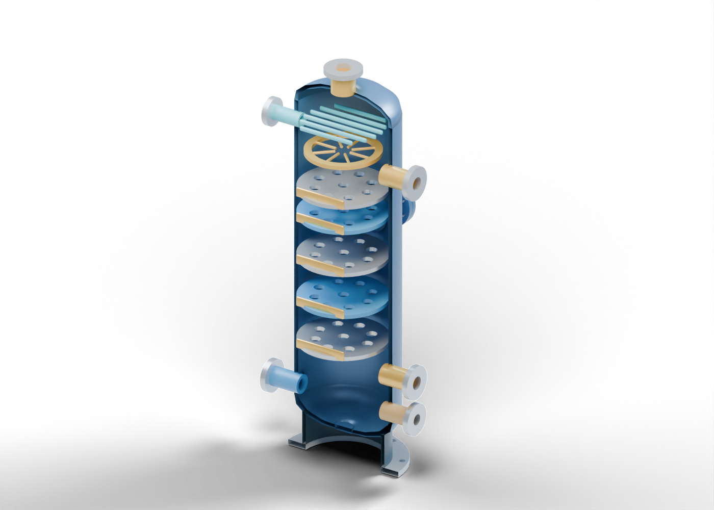
Regenerator hollow vessel wall
Vertical enclosure with independently drilled side openings. Invented teaching geometry; no solvent, pressure, heat, hydraulics, material, corrosion, emissions or service qualification.
Regenerator upper head
Hollow upper head with a central overhead passage. Invented teaching geometry; no solvent, pressure, heat, hydraulics, material, corrosion, emissions or service qualification.
Regenerator lower head
Hollow lower head with separate closed sump region. Invented teaching geometry; no solvent, pressure, heat, hydraulics, material, corrosion, emissions or service qualification.
Closed lower sump marker
Closed static lower boundary; no drain or vessel-opening method. Invented teaching geometry; no solvent, pressure, heat, hydraulics, material, corrosion, emissions or service qualification.
Regenerator support skirt
Raised hollow support location without foundation or load design. Invented teaching geometry; no solvent, pressure, heat, hydraulics, material, corrosion, emissions or service qualification.
Regenerator skirt base ring
Annular base with eight actual location bores. Invented teaching geometry; no solvent, pressure, heat, hydraulics, material, corrosion, emissions or service qualification.
Rich-solvent feed hollow neck
Open rich-solvent feed vessel boundary. Invented teaching geometry; no solvent, pressure, heat, hydraulics, material, corrosion, emissions or service qualification.
Rich-solvent feed bored flange
Separate bored connection marker; no flange class or joint design. Invented teaching geometry; no solvent, pressure, heat, hydraulics, material, corrosion, emissions or service qualification.
Reflux return hollow neck
Open reflux return vessel boundary. Invented teaching geometry; no solvent, pressure, heat, hydraulics, material, corrosion, emissions or service qualification.
Reflux return bored flange
Separate bored connection marker; no flange class or joint design. Invented teaching geometry; no solvent, pressure, heat, hydraulics, material, corrosion, emissions or service qualification.
Reboiler vapor return hollow neck
Open reboiler vapor return vessel boundary. Invented teaching geometry; no solvent, pressure, heat, hydraulics, material, corrosion, emissions or service qualification.
Reboiler vapor return bored flange
Separate bored connection marker; no flange class or joint design. Invented teaching geometry; no solvent, pressure, heat, hydraulics, material, corrosion, emissions or service qualification.
Reboiler liquid withdrawal hollow neck
Open reboiler liquid withdrawal vessel boundary. Invented teaching geometry; no solvent, pressure, heat, hydraulics, material, corrosion, emissions or service qualification.
Reboiler liquid withdrawal bored flange
Separate bored connection marker; no flange class or joint design. Invented teaching geometry; no solvent, pressure, heat, hydraulics, material, corrosion, emissions or service qualification.
Lean-solvent outlet hollow neck
Open lean-solvent outlet vessel boundary. Invented teaching geometry; no solvent, pressure, heat, hydraulics, material, corrosion, emissions or service qualification.
Lean-solvent outlet bored flange
Separate bored connection marker; no flange class or joint design. Invented teaching geometry; no solvent, pressure, heat, hydraulics, material, corrosion, emissions or service qualification.
Overhead acid-gas outlet hollow neck
Open overhead acid-gas outlet vessel boundary. Invented teaching geometry; no solvent, pressure, heat, hydraulics, material, corrosion, emissions or service qualification.
Overhead acid-gas outlet bored flange
Separate bored connection marker; no flange class or joint design. Invented teaching geometry; no solvent, pressure, heat, hydraulics, material, corrosion, emissions or service qualification.
Contacting deck 1
Open, perforated contacting-location marker; no actual tray sizing, downcomer or hydraulic result. Invented teaching geometry; no solvent, pressure, heat, hydraulics, material, corrosion, emissions or service qualification.
Deck 1 rim marker
Partial raised rim marker. It does not define an operating weir, seal or liquid level. Invented teaching geometry; no solvent, pressure, heat, hydraulics, material, corrosion, emissions or service qualification.
Contacting deck 2
Open, perforated contacting-location marker; no actual tray sizing, downcomer or hydraulic result. Invented teaching geometry; no solvent, pressure, heat, hydraulics, material, corrosion, emissions or service qualification.
Deck 2 rim marker
Partial raised rim marker. It does not define an operating weir, seal or liquid level. Invented teaching geometry; no solvent, pressure, heat, hydraulics, material, corrosion, emissions or service qualification.
Contacting deck 3
Open, perforated contacting-location marker; no actual tray sizing, downcomer or hydraulic result. Invented teaching geometry; no solvent, pressure, heat, hydraulics, material, corrosion, emissions or service qualification.
Deck 3 rim marker
Partial raised rim marker. It does not define an operating weir, seal or liquid level. Invented teaching geometry; no solvent, pressure, heat, hydraulics, material, corrosion, emissions or service qualification.
Contacting deck 4
Open, perforated contacting-location marker; no actual tray sizing, downcomer or hydraulic result. Invented teaching geometry; no solvent, pressure, heat, hydraulics, material, corrosion, emissions or service qualification.
Deck 4 rim marker
Partial raised rim marker. It does not define an operating weir, seal or liquid level. Invented teaching geometry; no solvent, pressure, heat, hydraulics, material, corrosion, emissions or service qualification.
Contacting deck 5
Open, perforated contacting-location marker; no actual tray sizing, downcomer or hydraulic result. Invented teaching geometry; no solvent, pressure, heat, hydraulics, material, corrosion, emissions or service qualification.
Deck 5 rim marker
Partial raised rim marker. It does not define an operating weir, seal or liquid level. Invented teaching geometry; no solvent, pressure, heat, hydraulics, material, corrosion, emissions or service qualification.
Upper feed distribution ring
Open ring marking a rich-feed distribution location; no actual distributor pattern. Invented teaching geometry; no solvent, pressure, heat, hydraulics, material, corrosion, emissions or service qualification.
Feed branch marker 1
Independent visual branch; no metered outlet or measured uniformity. Invented teaching geometry; no solvent, pressure, heat, hydraulics, material, corrosion, emissions or service qualification.
Feed branch marker 2
Independent visual branch; no metered outlet or measured uniformity. Invented teaching geometry; no solvent, pressure, heat, hydraulics, material, corrosion, emissions or service qualification.
Feed branch marker 3
Independent visual branch; no metered outlet or measured uniformity. Invented teaching geometry; no solvent, pressure, heat, hydraulics, material, corrosion, emissions or service qualification.
Feed branch marker 4
Independent visual branch; no metered outlet or measured uniformity. Invented teaching geometry; no solvent, pressure, heat, hydraulics, material, corrosion, emissions or service qualification.
Feed branch marker 5
Independent visual branch; no metered outlet or measured uniformity. Invented teaching geometry; no solvent, pressure, heat, hydraulics, material, corrosion, emissions or service qualification.
Feed branch marker 6
Independent visual branch; no metered outlet or measured uniformity. Invented teaching geometry; no solvent, pressure, heat, hydraulics, material, corrosion, emissions or service qualification.
Feed branch marker 7
Independent visual branch; no metered outlet or measured uniformity. Invented teaching geometry; no solvent, pressure, heat, hydraulics, material, corrosion, emissions or service qualification.
Feed branch marker 8
Independent visual branch; no metered outlet or measured uniformity. Invented teaching geometry; no solvent, pressure, heat, hydraulics, material, corrosion, emissions or service qualification.
Overhead entrainment marker 1
Overhead location marker; no acid-gas separation or mist-removal result. Invented teaching geometry; no solvent, pressure, heat, hydraulics, material, corrosion, emissions or service qualification.
Overhead entrainment marker 2
Overhead location marker; no acid-gas separation or mist-removal result. Invented teaching geometry; no solvent, pressure, heat, hydraulics, material, corrosion, emissions or service qualification.
Overhead entrainment marker 3
Overhead location marker; no acid-gas separation or mist-removal result. Invented teaching geometry; no solvent, pressure, heat, hydraulics, material, corrosion, emissions or service qualification.
Overhead entrainment marker 4
Overhead location marker; no acid-gas separation or mist-removal result. Invented teaching geometry; no solvent, pressure, heat, hydraulics, material, corrosion, emissions or service qualification.
Overhead entrainment marker 5
Overhead location marker; no acid-gas separation or mist-removal result. Invented teaching geometry; no solvent, pressure, heat, hydraulics, material, corrosion, emissions or service qualification.
Overhead entrainment marker 6
Overhead location marker; no acid-gas separation or mist-removal result. Invented teaching geometry; no solvent, pressure, heat, hydraulics, material, corrosion, emissions or service qualification.
Closed access hollow neck
Hollow access-boundary envelope. Invented teaching geometry; no solvent, pressure, heat, hydraulics, material, corrosion, emissions or service qualification.
Closed access bored flange
Drilled illustrative flange, without a qualified pressure joint. Invented teaching geometry; no solvent, pressure, heat, hydraulics, material, corrosion, emissions or service qualification.
Closed access gasket location
Gasket position only; no seal or compression result. Invented teaching geometry; no solvent, pressure, heat, hydraulics, material, corrosion, emissions or service qualification.
Closed access cover
Solid cover; section control is no permission or procedure for entry. Invented teaching geometry; no solvent, pressure, heat, hydraulics, material, corrosion, emissions or service qualification.
Closed access smooth stud 1
Smooth location marker; no thread, preload or opening instruction. Invented teaching geometry; no solvent, pressure, heat, hydraulics, material, corrosion, emissions or service qualification.
Closed access smooth stud 2
Smooth location marker; no thread, preload or opening instruction. Invented teaching geometry; no solvent, pressure, heat, hydraulics, material, corrosion, emissions or service qualification.
Closed access smooth stud 3
Smooth location marker; no thread, preload or opening instruction. Invented teaching geometry; no solvent, pressure, heat, hydraulics, material, corrosion, emissions or service qualification.
Closed access smooth stud 4
Smooth location marker; no thread, preload or opening instruction. Invented teaching geometry; no solvent, pressure, heat, hydraulics, material, corrosion, emissions or service qualification.
Closed access smooth stud 5
Smooth location marker; no thread, preload or opening instruction. Invented teaching geometry; no solvent, pressure, heat, hydraulics, material, corrosion, emissions or service qualification.
Closed access smooth stud 6
Smooth location marker; no thread, preload or opening instruction. Invented teaching geometry; no solvent, pressure, heat, hydraulics, material, corrosion, emissions or service qualification.
Closed access smooth stud 7
Smooth location marker; no thread, preload or opening instruction. Invented teaching geometry; no solvent, pressure, heat, hydraulics, material, corrosion, emissions or service qualification.
Closed access smooth stud 8
Smooth location marker; no thread, preload or opening instruction. Invented teaching geometry; no solvent, pressure, heat, hydraulics, material, corrosion, emissions or service qualification.